Analog-to-digital converters (ADC's) are of course fundamental ... errors originated by the integral nonlinearity (INL) is a ... differential nonlinearity (DNL) [3].
Chebyshev Polynomials and Dither Techniques for Static Characteristic Linearization in A/D Converters F. Attivissimo, N. Giaquinto and M. Savino Laboratory for Electric and Electronic Measurements Department of Electrics and Electronics (DEE) – Polytechnic of Bari Via E. Orabona 4, 70125 Bari - Italy Phone: +39 080 5963318 Fax +39 080 5963410 e-mail: [attivissimo, giaquinto]@deemis06.poliba.it Abstract – The paper illustrates a new procedure, simple and very fast, to measure and correct the linearity error in A/D converters. The method is based on the Chebyshev polynomial synthesis of the static characteristic via frequencydomain analysis, and is especially effective for dithered converters. Keywords: A/D converters, dithering, linearization, spectral techniques, Chebyshev polynomials.
I
INTRODUCTION
Analog-to-digital converters (ADC’s) are of course fundamental components in the field of electronic measurements, and measuring and correcting systematic errors originated by the integral nonlinearity (INL) is a deeply investigated issue. In a previous paper [1] the authors has proposed the use of the Fast Fourier Transform (FFT) to derive the INL of a converter. This technique is much faster than the customary and very accurate histogram test [2] and derives the INL in parametric form as a linear combination of Chebyshev polynomials. The price to be paid for the greater speed is that this frequency-domain test measures only the "smooth part" of the nonlinearity, without detecting the "granular part". In other words, the polynomial approximation hides the very fast variations in the nonlinearity and does not yield information about the differential nonlinearity (DNL) [3]. For the same reasons, measuring the nonlinearity via FFT (a method that we will call Chebyshev test in this paper) is much more effective when dealing with dithered converters [4]. The characteristic of a dithered ADC is indeed a smoothed version of the original quantization characteristic; on the other hand, the enormous number of codes of a dithered converter makes the histogram test quite difficult and unpractical. This paper resumes and develops the concepts briefly outlined above, showing that the frequency-domain measurement of nonlinearity allows also implementing an original and efficient linearization algorithm. The proposed linearization makes good use of the parametric
description of the static characteristic yielded by the test, and is an alternative to the usual lookup table technique [5]. With the proposed technique, the measurement and the correction of the nonlinearity are strictly connected in a single fast and simple procedure, which is especially advantageous in connection with the dither technique.
II
CHEBYSHEV (FFT) TEST OF NONLINEARITY FOR ADC
The FFT test for A/D converters is usually performed to obtain frequency-domain figures of merit, like the Total Harmonic Distortion (THD) or the Spurious-Free Dynamic Range (SFDR). The same test is able, however, to yield a different and very useful kind of information about the converter: the integral nonlinearity, which is usually measured with different techniques, mainly the histogram test [2]. If the input of a nonlinear static characteristic g ( x) is a sine wave with zero phase: x(t ) = V cos(2π ⋅ f ⋅ t ) + C
(1)
then g ( x) can be derived by the Fourier coefficients cn of the distorted sinusoidal output: g ( x (t ) ) =
c0 ∞ + ∑ cn cos(n ⋅ 2π ⋅ f ⋅ t ) . 2 n =1
(2)
The nonlinear characteristic is obtained, indeed, simply by solving (1) with respect to 2π ⋅ f ⋅ t , and substituting the result in (2). This operation is equivalent to substituting the cosine functions in (2) with the Chebyshev polynomials Cn ( z ) = cos(n ⋅ arccos( z )) : g ( x) =
c0 ∞ x −C + ∑ cn C n 2 n =1 V
(3)
In order to use this formula and reconstruct the
nonlinear characteristic g ( x) , one must perform a normal FFT test with the following simple conditions: 1) the input sine wave must have zero phase, so that the output Fourier coefficients cn are real; 2) coherent sampling is used. Condition 1) does not need to be actually accomplished in the analog domain: in practice one can digitize a sinusoid with arbitrary phase, provided the resulting complex Fourier coefficients are properly “rotated”, becoming the signed real coefficients that would be obtained with a zero-phase input. Condition 2) is needed to obtain the best estimate of the coefficients cn directly from the FFT bins of the output. If it cannot be met, the coefficients can be of course derived using well-known spectral analysis techniques like e.g. windowing and interpolation. The analog frequency of a modern sinusoidal generator for ADC testing, however, can be usually adjusted with great precision, so there is no need to make things more problematic with non-coherent sampling. In the following we will call this particular FFT test, performed with the conditions 1) and 2), and followed by the evaluation of g ( x) by means of Chebyshev polynomial, a Chebyshev test of nonlinearity. Its result is h( x ) =
c0 Na x−C + ∑ cn C n 2 n =1 V
(4)
where N a is the number of harmonics considered in the reconstruction. This is a polynomial of order N a that approximate the static characteristic g ( x) of the tested converter. A Chebyshev test performed with a finite number of samples gives a “perfect” reconstruction of the static characteristic, provided that a sufficient number of samples are acquired, and that g ( x(t ) ) has a finite number of harmonics. This third condition, unfortunately, is never met with reasonable approximation by actual A/D converters, as the nonlinear characteristic g ( x) has many quantization “jumps” that produces an infinite number of harmonics. Even the mere INL of a practical converter (i.e., g ( x ) without quantization error) is usually a very erratic function that produces too many harmonics. The fact that an actual ADC does not generate a finite number of harmonics means simply that g ( x) cannot be accurately described by a polynomial of finite order. This negative circumstance does not imply, however, that the method is of no practical use with A/D
converters. As shown in [1], the Chebyshev test provides a smooth function that approximates, in a least-squares sense, the INL of the converter. Even if this approximation cannot compete in accuracy with the result of a static test or a histogram test of nonlinearity, it comes with two significant advantages. First, the Chebyshev test is very fast: it can be performed satisfactorily with about 8,000 samples, regardless the ADC resolution [3]. Compared with the histogram test, which is very accurate but unable to give acceptable results without using at least one hundred samples per output code [IEEE], the frequency-domain procedure is a very interesting trade-off of accuracy for speed. The second advantage is that the Chebyshev test gives the INL in a parametric form with a selectable number of coefficients. Practical experience has shown [4, 3] that a good reconstruction of the nonlinearity, regardless for the ADC resolution, is given typically by 30 to 70 coefficients: the actual number is not critical for the final result, as fewer coefficients simply give a smoother approximation. The parametric form of the INL does not seem much useful for assessing the ADC performance, but one senses that it could be employed to implement an efficient linearization algorithm. Summing up, as far as ordinary A/D converters are concerned, the Chebyshev test has peculiar features that make it useful, at least for a fast nonlinearity check; but the histogram test remains mandatory to measure accurately the INL. However, if one considers dithered ADC’s – characterized by a far higher number of output codes and a smoother nonlinear characteristic – the picture is altered and the Chebyshev test becomes even more useful than the histogram. This is explained with more detail in the next section.
III CHEBYSHEV TEST OF DITHERED ADC’S The dithering technique is more and more used nowadays in practical DAQ devices. A certain amount of “noise” is added to the signal before the conversion, and subsequently removed by subtraction, averaging and/or filtering in the digital domain. As a result, almost all the quantization error and part of the linearity error are removed. Mathematically, this is simply summarized by the equation y=∫
+∞
−∞
g ( x + n ) ⋅ f ( n ) dn = g ∗ f ( − x ) = g d ( x )
(5)
where g ( x) is the nonlinear static characteristic of the ADC, f (n) the probability density function (pdf) of the dither signal, and g d ( x) is the resulting static
2
2
1.5
1
0.5
static error [LSB]
characteristic of the dithered ADC. Due to the convolution, this characteristic is a smoothed (low-pass filtered) version of the original nonlinearity g ( x) . Speaking about dithered ADC’s, it must be considered first of all that the histogram test cannot be performed directly, because this kind of converter has by far too many output codes (this is precisely the aim of the dither technique). The histogram test can be used only to determine g ( x) , by eliminating the dither, and then g d ( x) can be obtained via (5) (but the pdf f (n) must be known) [5]. On the basis of the above considerations the Chebyshev test of nonlinearity, which is easier to perform for high-resolution converters, and is more accurate when measuring smoother nonlinearities, seems very well suited for dithered converters. Experiments with actual dithered converters have in fact shown that [4] the Chebyshev test is able in favorable cases to measure the static characteristic g d ( x) with an error below 0.1 LSB. If the original characteristic g ( x) of the dithered converter has very wide “jumps”, the error of the Chebyshev test can be locally higher, but is all the same equal to fractions of LSB in most of the full-scale range. Two examples that illustrate the performance of the Chebyshev test with dithered ADC’s are reported in Figs. 1a and 1b. We have employed simulated converters in the examples, in order to compare the performance of the method with the “truth”, and to illustrate more precisely its behavior with different kind of INL. The first converter (Fig. 1a) has a more erratic INL and is therefore dithered with a larger Gaussian noise (1.5 LSB rms); the second (Fig. 1b) has a smoother INL and the employed dither is consequently smaller (1.0 LSB rms).
0
−0.5
−1
−1.5
−2 −0.5
−0.2
−0.1
0 0.1 input voltage [V]
0.2
0.3
0.4
0.5
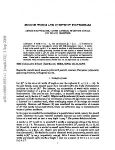
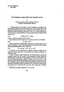
The figures compare the true overall nonlinearity g d ( x) − x of the dithered ADC’s with the measurement provided by the Chebyshev test, performed with 16,384 samples and using 50 harmonics to reconstruct g d ( x) . The integral nonlinearity of the converter without dither (this is not the overall nonlinearity g ( x) − x , that includes also a quantization error of ± 0.5 LSB) is reported for comparison. The simulated ADC n. 1, having a more irregular INL and a larger dither signal, shows more clearly the smoothing effect of the dither on the characteristic. In the ADC n. 2 the overall nonlinearity after dithering is more similar to the original INL, because of the smaller dither and of the intrinsic smoothness of the INL. In other words, in the first case the dither has both eliminated the quantization error and removed part of the INL error, while in the second case it has only removed quantization, leaving intact the INL. Tab. 1 – Figures of merit for the simulated ADC ADC 1 ADC 1 ADC 2 ADC 2 w/o dither with dither w/o dither with dither
1
0.5
static error [LSB]
−0.3
Fig. 1b – Simulated ADC n. 2: true INL without dither (dashed line), true overall nonlinearity using dither (thin line), overall nonlinearity using dither as measured by the Chebyshev test (thick line).
1.5
0
−0.5
Emax
2.38 LSB
1.58 LSB
2.13 LSB
1.50 LSB
be
6.13 bit
6.28 bit
6.20 bit
6.26 bit
Table 1 reports two important figures of merit for the simulated ADC’s, i.e. the maximum static error Es = max | y − x | and the number of effective bits
−1
−1.5
−2 −0.5
−0.4
−0.4
−0.3
−0.2
−0.1
0 0.1 input voltage [V]
0.2
0.3
0.4
0.5
Fig. 1a – Simulated ADC n. 1: true INL without dither (dashed line), true overall nonlinearity using dither (thin line), overall nonlinearity using dither as measured by the Chebyshev test (thick line).
be =
x 2 /12 1 log 2 FS 2 2 σe
(6)
being xFS the full-scale range and σ e2 the variance of
the global error y − x . These figures provide a quantitative evaluation of the performance improvement due to the dither. As regards the maximum static error, the table shows in the first ADC a reduction of 0.8 LSB (due to the smoothing of the INL), and in the second of 0.5 LSB (only quantization error has been eliminated). As regards the number of effective bits, from the table emerges a moderate increase: only of 0.x bits in the first case and 0.y bits in the second. This is obviously due to the “large-scale nonlinearities” [5] left intact by the dither, as clearly visible in Figs. 1a and 1b. By comparing the moderate increase in be with the infinite effective resolution theoretically expected for perfectly linear dithered ADC’s, one can understand that the performance could be greatly increased by removing the residual nonlinearity via linearization. This is in principle quite simple, consisting in the inversion of the dithered nonlinear characteristic g d ( x) : −1 d
−1 d
y ' = g ( y ) = g ( g d ( x )) = x
(7)
The trouble is that, dealing with dithered converters with a huge number of output codes, the inversion cannot be performed with the customary technique of a lookup table, which associates to each output code y the corresponding y ' � x . The only practical way to employ a lookup table is constructing it only for some points of the characteristic, and evaluating the proper correction for different points with some kind of interpolation [5]. If one has measured g d ( x) with the Chebyshev test, however, there is another possible solution, based on the parametric form of the approximated static characteristic h( x ) .
IV REMOVING A SMOOTH NONLINEARITY KNOWN IN PARAMETRIC FORM Using h −1 ( x ) to correct the linearity error is equivalent, of course, to solve the nonlinear equation y0 = h( x ) , for each output sample y0 . As the formula (4) is not analytically invertible, this appears at first glance a cumbersome numerical task. It can be made, instead, very simple and direct. It must be considered that h( x) , being the smoothed static characteristic of an A/D converter, is a quite particular function. First of all, for a monotonic converter it is single-valued and monotonic in its definition interval [−V + C , V + C ] , and is therefore univocally invertible. Also an ADC with sporadic nonmonotonicities is very likely to produce a monotonic g d ( x) and consequently h( x) , because of the
smoothing action of the dither. Second, h( x ) closely approximates a straight line with slope G and, since it does not have sudden jumps or variations, it is very likely that its slope is close enough to G, so that dh( x ) −G