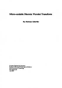
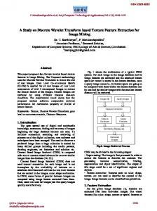
an application of discrete wavelet transform (WT) and complex wavelet transform
(CWT) in image processing problem such as hybrid skeletonization.
COMPARISON OF DISCRETE WAVELET TRANSFORM AND COMPLEX WAVELET TRANSFORM IN HYBRID SKELETONIZATION BASED ON CVANN Murat CEYLAN1 Osman Nuri UCAN2 Yüksel ÖZBAY3 Rachid JENNANE4 Gabriel AUFORT5 Claude Laurent BENHAMOU6 ABSTRACT Curve and surface thinning are widely-used skeletonization techniques for modeling objects in 3 dimensions. In the case of disordered porous media analysis, however, neither is really efficient since the internal geometry of the object is usually composed of both rod and plate shapes. This paper concludes an application of discrete wavelet transform (WT) and complex wavelet transform (CWT) in image processing problem such as hybrid skeletonization of trabecular bone images. Hybrid skeleton combines 2D surfaces and 1D curve to represent respectively the plate-shaped and rod-shaped parts of the object. For hybrid skeletonization, two cascade structures are proposed. In these structures, features of images were extracted with discrete wavelet transform and complex wavelet transform. After that, obtained features were used as 1
Selçuk University, Department of Electrical and Electronics Engineering. Istanbul Aydın University, Department of Electrical and Electronics Eng. 3 Konya Selçuk University, Eng. Faculty.Konya 4 Instiut PRISME / LESI, University of Orleans. 5 Equipe INSERM U658, Hospital of Orleans. 6 Orleaans, France 2
COMPARISON OF DISCRETE WAVELET TRANSFORM AND COMPLEX WAVELET TRANSFORM IN HYBRID SKELETONIZATION BASED ON CVANN
inputs of complex-valued artificial neural network (CVANN) which is multilayered artificial neural networks with two dimensions (real and imaginary parts). Effects of the feature extraction methods are compared for ability of the hybrid skeletonization on a trabecular bone sample. Results show that the CWT succeeded to hybrid skeletonization with lower error rate than WT. Key Words: Wavelet transform, complex wavelet transform, complex-valued artificial neural network, hybrid skeletonization. 1. Introduction Skeletonizing an object often requires a compromise between minimum thinness, homotopic equivalence, geometry preservation and reversibility, which are usually incompatible. For example, algorithms based on distance transforms [1,2] are usually reversible but lose the connectivity information. 3D thinning [3,4] is another method based on iterative erosions of an object until only its skeleton is left. The most widely-used thinning variants are curve and surface thinning. Curve thinning techniques [5,6] generate skeletons composed of 1D curves. On the other hand, surface thinning techniques [7-11] generate 2D surfaces which better preserve the plates geometry, but do not thin rod shapes enough. Curve thinning and surface thinning are efficient respectively for one or the other, but not for both. For example, in the case of trabecular bone, it is clearly established that the structure is composed of both rod and plate parts. A lot of work has been carried out on the characterization of this porous medium, especially using skeletons. In this paper, effects of WT and CWT in the skeletonizing hybridshaped media composed of rods and plates using CVANN were studied. It is expected that complex-valued artificial neural networks (CVANN) whose parameters (weights, threshold values, inputs and outputs) are all complex numbers, will have applications in fields dealing with signal processing [12-14] and image processing [15,16]. When using the existing method for real numbers, we must apply the method individually to their real and imaginary parts. On the other hand, complex-valued neural networks allow us to directly process data.
28
MURAT CEYLAN,OSMAN NURĐ UCAN,YÜKSEL ÖZBAY RACHĐD JENNANE,GABRĐEL AUFORT,CLAUDE LAURENT BENHAMOU
2. Curve Thinning Algorithm (CTA) and Surface Thinning Algorithm (STA) The geometrical characterization of a porous medium using a thinning technique basically depends on the type of skeleton needed to model the material structure. Figure 1 shows the limitations of the curve and surface skeletons on a trabecular bone sample. In the curve case (b), plate-shaped zones are not efficiently described. In the surface case (c), the object shape is accurate but rod zones are not sufficiently thinned. Furthermore, the curve skeleton is sensitive to object surface irregularities, and generates many unexpected small segments.
(a)
(b)
(c)
Figure 1: A trabecular bone sample (a), its curve skeleton (b) and its surface skeleton (c).
2.1 Curve Thinning Algorithm (CTA) The curve thinning algorithm used in this paper is based on the well established work of Morgenthaler [17]. This iterative process relies on the evaluation of the Betti numbers in each voxel’s neighbourhood. A voxel is said
29
COMPARISON OF DISCRETE WAVELET TRANSFORM AND COMPLEX WAVELET TRANSFORM IN HYBRID SKELETONIZATION BASED ON CVANN
to be removable if its deletion does not change these numbers. Voxels are removed sequentially if they match the deletion criterions, which ensures a perfect topology preservation. The process is repeated until only the curve skeleton remains. Figure 1.b shows the result of the curve thinning algorithm on the bone volume of figure 1.a. In this example, plate zones have fully disappeared, which confirms that curve thinning is not sufficient to describe the entire porous medium. However, it efficiently models the rod-shaped parts of the object.
2.2 Surface Thinning Algorithm (STA) There are different types of surface skeletons, depending on the erosion conditions used in the case of thinning algorithms. Several surface thinning algorithms have been compared [9,11,18-20]. They all preserve the connectivity of the object. The important constraint in this work was to obtain a simple and relevant surface geometry in order to use the new skeleton as a basis for structural models. The MESPTA (Modified Extended Safe Point Thinning Algorithm) algorithm, [8,19,21] appeared to give the simplest surface geometry. The MESPTA consists in an iterative parallel topology-preserving process that transforms an object into its medial surface. The main advantage of this technique is that it generates a simple surface geometry, which is convenient to model the plate-shaped parts of an object. In the hybrid thinning technique, all plate voxels that match the safe point condition as explained in [19] are deleted at the end of an iteration. The process is iterated until no voxel is deleted. Figure 1.c shows the result of the MESPTA on the bone volume of figure 1.a, which has been thinned to simple 2D subsets.
30
MURAT CEYLAN,OSMAN NURĐ UCAN,YÜKSEL ÖZBAY RACHĐD JENNANE,GABRĐEL AUFORT,CLAUDE LAURENT BENHAMOU
2.3 Discrete Wavelet Transform Wavelet is a powerful tool for representing nonlinearity [22]. A function f ( x) can be represented by the superposition of daughters ψ a ,b ( x) of a mother wavelet ψ ( x) . Where ψ a ,b ( x) can be expressed as
ψ a ,b ( x ) =
1 x−b ψ a a
(1)
a ∈ R+ and b ∈ R are, respectively, called dilation and translation parameters. The continuous wavelet transform of f ( x ) is defined as ∞
w(a, b) =
∫
f ( x)ψ a ,b ( x)dx
(2)
−∞
and the function f ( x ) can be reconstructed by the inverse wavelet transform ∞ ∞
f ( x) =
∫ ∫ w(a, b)ψ
−∞ −∞
a ,b
( x)
da.db . a2
(3)
The continuous wavelet transform and its inverse transform are not directly implementable on digital computers. When the inverse wavelet transform is discretized, f ( x ) has the following approximate wavelet-based representation form:
31
COMPARISON OF DISCRETE WAVELET TRANSFORM AND COMPLEX WAVELET TRANSFORM IN HYBRID SKELETONIZATION BASED ON CVANN
K x − bk f ( x) ≈ ∑ wkψ , k =1 ak
∧
(4)
where the wk , bk and ak are weight coefficients, translations and dilations for each daughter wavelet [22]. 2.4 Complex discrete wavelet transform (CWT) Wavelet techniques are succesfully applied to various problems in signal and image processing. Data compression [23], motion estimation [24], segmentation and classification [25, 26] and denoising [27] are only some examples. It is perceived that the wavelet transform is an important tool for analysis and processing of signals and images. In spite of its efficient computational algorithm, the wavelet transform suffers from three main disadvantages. Limitations of wavelet transform Although the standart DWT is a powerful tool, it has three major disadvantages that undermines its application for certain signal and image processing tasks [28, 29]. a) Shift sensitivity A transform is shift sensitive, if the shifting in time, for input-signal causes an unpredictable change in transform coefficients. It has been observed that the Standard DWT is seriously disadvantaged by the shift sensitivity that arises from down samplers in the DWT implementation [28, 30]. Shift sensitivity is an undesirable property because it implies that DWT coefficients fail to distinguish between input-signal shifts. b) Poor directionality
32
MURAT CEYLAN,OSMAN NURĐ UCAN,YÜKSEL ÖZBAY RACHĐD JENNANE,GABRĐEL AUFORT,CLAUDE LAURENT BENHAMOU
An m- Dimensional transform (m>1) suffers poor directionality when the transform coefficients reveal only a few feature orientations in the spatial domain. Wavelet transform has been poor directional selectivity for diagonal fetaures. Because the wavelet filters are separable and real. c) Absence of phase information For a complex-valued signal or vector, its phase can be computed by its real and imaginary projections. Phase information is valuable in many signal and image processing applications [31] such as e.g. in image compression and power measurument [32, 33]. Most DWT implementations use separable filtering with real coefficient filters associated wih real wavelets resulting in real-valued approximations and details. Such DWT implementations cannot provide the local phase information. All natural signal are basically real-valued, hence to avoid the local phase information, complex-valued filtering is required [34, 35]. Recent research in the development of CWTs can be broadly classified in two groups; RCWT (Redundant CWTs) and NRCWT (Non-redundant CWTs). Standart DWT is critically decimated and gives N samples in transform domain for the same N samples of a given signal. While the redundant transform gives M samples in transform domain for N samples of given input signal (where M>N) and hence it is expensive by the factor M/N. The NRCWT follows the design aim to approach towards N samples in transform domain for a given N input samples [28, 29]. The RCWT include two almost similar CWTs. They are denoted as DTDWT (Dual-Tree DWT based CWT, see Figure 2) with two almost similar versions namely Kingsbury’s and Selesnick’s [36]. In this paper, we used Kingsbury’s CWT [27, 35] for feature extraction of image to be segmented.
33
COMPARISON OF DISCRETE WAVELET TRANSFORM AND COMPLEX WAVELET TRANSFORM IN HYBRID SKELETONIZATION BASED ON CVANN
Level
Level
h0
h1
h0
2
h1
2
2
Tree a
2
Imaginary Tree
f (t )
Tree b
Real
g0
g1
g0
2
g1
2
2
2
Figure 2: Complex Wavelet Transform with two level 2.5 Complex-Valued Artificial Neural Network (CVANN) Recently, there has been an increased interest in applications of the CVANN to process complex signals [37-39]. In this study, a complex backpropagation (CBP) algorithm has been used for image segmentation. We will first give the theory of the CBP algorithm as applied to a multi layer CVANN. Figure 3 shows a CVANN model used in the study.
34
MURAT CEYLAN,OSMAN NURĐ UCAN,YÜKSEL ÖZBAY RACHĐD JENNANE,GABRĐEL AUFORT,CLAUDE LAURENT BENHAMOU
Figure 3: A model neuron used in the complex-BP algorithm.
The input signals, weights, thresholds, and output signals are all complex numbers. The activity Yn of neuron n is defined as:
Yn = ∑ Wnm X m + Vn
(5)
m
where Wnm is the complex-valued (CV) weight connecting neuron n and m, Xm is the CV input signal from neuron m, and Vn is the CV threshold value of
35
COMPARISON OF DISCRETE WAVELET TRANSFORM AND COMPLEX WAVELET TRANSFORM IN HYBRID SKELETONIZATION BASED ON CVANN
neuron n. To obtain the CV output signal, the activity value Yn is converted into its real and imaginary parts as follows:
Yn = x + iy = z where i denotes
(6)
− 1 . Although various output functions of each neuron can be
considered, the output function used in this study is defined by the following equation:
f C ( z ) = f R ( x) + i. f R ( y )
(7)
where fR(u) is called the activation function of neural network. One of the difficulties encountered in applying the CBP algorithm to the complex domain involves the appropriate choice of activation function. For a practical implementation of the complex multilayer perceptron, it is necessary that the activation function be bounded. Several researchers developed a set of properties that a complex activation function must satisfy in order to be useful in a multilayer perceptron trained with the back-propagation algorithm [40]. Complex activation function that used in this study is a superposition of real and imaginary logarithmic sigmoids, as shown by
fR (u ) =
1 1 +j 1 + exp(−u R ) 1 + exp(−u I )
Summary of CBP algorithm: 1. Initialization Set all the weights and thresholds to small complex random values.
36
(8)
MURAT CEYLAN,OSMAN NURĐ UCAN,YÜKSEL ÖZBAY RACHĐD JENNANE,GABRĐEL AUFORT,CLAUDE LAURENT BENHAMOU
2. Presentation of input and desired (target) outputs Present the input vector X(1), X(2),….,X(N) and corresponding desired (target) response T(1), T(2),….T(N), one pair at a time, where N is the total number of training patterns. 3. Calculation of actual outputs To obtain the complex-valued output signal, the activity value Yn is converted into its real and imaginary parts as follows:
Yn = x + iy = z where i denotes
(9)
−1 .
4. Calculation of the stopping criteria with respect to Eq(10) [38]. If this condition is satisfied, algorithm is stopped and weights and biases are frozen. N
∑ ∑T
( p) n
p
2
−O
( p) n
= 10 −1
(10)
n =1
where Tn(p) and On(p) are complex numbers and denote the desired and output value, respectively. The actual output value of the neuron n for the pattern p, i.e the left side of (Eq 10) denotes the error between the desired output pattern and the actual output pattern. N denotes the number of neurons in the output layer. 5. Adaptation of weights and thresholds
37
COMPARISON OF DISCRETE WAVELET TRANSFORM AND COMPLEX WAVELET TRANSFORM IN HYBRID SKELETONIZATION BASED ON CVANN
We will use Wml for the weight between the input neuron l and the hidden neuron m, Vnm for the weight between the hidden neuron m and the output neuron n, θm for the threshold of the hidden neuron m, and γn for the threshold of the output neuron n. Let Il, Hm, On denote the output values of the input neuron l, the hidden neuron m, and the output neuron n, respectively. Let also Um and Sn denote the internal potentials of the hidden neuron m and the output neuron n, respectively. Um, Sn, Hm, and On can be defined respectively as
U m = ∑ Wml I l + θ m , S n = ∑ Vnm H m + γ n , Hm=fc(Um), and On= fc(Sn). Let l
m
δn=Tn-On denote the error between the actual pattern On and the target pattern Tn of output neuron n. We will define the square error for the pattern p as
( 2 )∑ T
Ep = 1
N
2
n
− On , where N is the number of output neurons.
n =1
We can show that the weights and the thresholds should be modified according to the following equations [38].
∆Vnm = −ε .
∆γ n = −ε .
∆Wml = −ε
∂E p
∂ Re[Vnm ]
∂E p
∂ Re[γ n ] ∂E p
− i.ε
∂ Re [Wml ]
∂E p
− i.ε
∂ Im[Vnm ]
∂E p
∂ Im[γ n ]
− i.ε
∂E p
∂ Im [Wml ]
38
(11)
(12)
(13)
MURAT CEYLAN,OSMAN NURĐ UCAN,YÜKSEL ÖZBAY RACHĐD JENNANE,GABRĐEL AUFORT,CLAUDE LAURENT BENHAMOU
∆θ m = −ε
∂E p
∂ Re[θ m ]
− i.ε
∂E p
∂ Im[θ m ]
(14)
Equations (11)-(14) can be expressed as:
∆Vnm = H m ∆γ n
(15)
[ ]
Re δ n (1 − Re[On ]) Re[On ] ∆γ n = ε + i. Im δ n (1 − Im[O ]) Im[O ] n n
(16)
∆Wml = I l ∆θ m
(17)
[ ]
(1 − Re[H m ]) Re[H m ] Re δ n (1 − Re[On ]) ∆θ m = ε Re[On ] Re[Vnm ] × ∑ n + Im δ n (1 − Im[On ]) Im[O ] Im[V ] n nm
[ ]
[ ]
39
COMPARISON OF DISCRETE WAVELET TRANSFORM AND COMPLEX WAVELET TRANSFORM IN HYBRID SKELETONIZATION BASED ON CVANN
(1 − Im[H m ]) Im[H m ] n Re δ (1 − Re[On ]) − iε Re[On ]Im[Vnm ] × ∑ n − Im δ n (1 − Im[On ]) Im[O ]Re[V ] n nm
[ ]
(18)
[ ]
where z denotes the complex conjugate of a complex number z. Calculation of Training and Test Errors: The training and test errors given in tables were found according to Eq. (19).
k ∑ t (i ) − a (i ) Error (% ) = i =1 m*n
* 100
(19)
where t(i) is desired outputs, a(i) is outputs of neural network, k is the number of samples in training or test data, m is the number of segments in training or test data and n is the number of outputs of neural network for training and test procedures [12]. 40
MURAT CEYLAN,OSMAN NURĐ UCAN,YÜKSEL ÖZBAY RACHĐD JENNANE,GABRĐEL AUFORT,CLAUDE LAURENT BENHAMOU
3. Results In this paper, 3D thinning of hybrid shaped porous media is realized using CWT-CVANN. Firstly, 2D slices were extracted from the 3D objects using curve thinning (CTA) and surface thinning (STA). Then, CTA and STA parts of image are determined as real and imaginary parts of input image, respectively. Features of the obtained complex-valued images (CTA + i.STA) are extracted using CWT with two levels. For the second level of CWT, input matrix size of images was reduced to 32x32 from 128x128 (original image size). These new feature vectors are used to CVANN as inputs. The outputs of CVANN are separated to real (CTA) and imaginary (STA) components as illustrated in Figure 4. For comparison, WT was used for feature extraction of CTA and STA, separately. Daubechies 2 function is selected as wavelet function and applied with two levels. Thus, size of CTA and STA was reduced to 32x32. Obtained new images of CTA and STA were coded as complex-valued (CTA + i.STA). Figure 5 shows the hybrid skeleton process using WT-CVANN.
Figure 4. Hybrid skeletonization process using CWT-CVANN (ICWT: Inverse CWT )
41
COMPARISON OF DISCRETE WAVELET TRANSFORM AND COMPLEX WAVELET TRANSFORM IN HYBRID SKELETONIZATION BASED ON CVANN
Figure 5. Hybrid skeletonization process using WT-CVANN (IWT: Inverse WT) The complex-valued backpropagation algorithm is used for training of the proposed networks. In training phase, the weights and biases of CVANNs are initialized with small random complex numbers. An error goal (stopping criteria of training of 10-1) is specified as in equation (10). The training of WTCVANN and CWT-CVANN is stopped when the error goal is achieved. Then, performance of networks is tested by presenting test images. The optimum learning rate and numbers of hidden nodes are determined as 0.7 and 60, respectively, via experimentation. Number of iterations is determined as 1000 for all structures. Test results are presented in Table-1. As seen in Table-1, the second level CWT –CVANN structure achieves good results than WT-CVANN. Error rate is 0.1317 % for CWT-CVANN. For the same images, higher error than CWT-CVANN is obtained using WT-CVANN. Error of WT-CVANN is calculated as 0.7225 %. The resulting output images using two structures for random selected input images are given in Figure 6, Figure 7 and Figure 8. These images show that, using WT as feature extractor for hybrid
42
MURAT CEYLAN,OSMAN NURĐ UCAN,YÜKSEL ÖZBAY RACHĐD JENNANE,GABRĐEL AUFORT,CLAUDE LAURENT BENHAMOU
skeletonization task generates artifacts in the images, especially imaginary part of image (STA). These artifacts are occurred high error in the image analysis.
43
COMPARISON OF DISCRETE WAVELET TRANSFORM AND COMPLEX WAVELET TRANSFORM IN HYBRID SKELETONIZATION BASED ON CVANN
Table 1. CWT-CVANN and WT-CVANN results for 10 different images
WT-CVANN
CWT-CVANN
Error (%)
Error (%)
1
0.5053
0.0873
2
0.6667
0.1272
3
0.6892
0.0480
4
0.7527
0.1896
5
0.6991
0.1056
6
0.6982
0.1181
7
0.6307
0.1474
8
1.0897
0.2808
9
0.7798
0.1421
10
0.7140
0.0710
AVERAGED
0.7225
0.1317
Patient File
44
MURAT CEYLAN,OSMAN NURĐ UCAN,YÜKSEL ÖZBAY RACHĐD JENNANE,GABRĐEL AUFORT,CLAUDE LAURENT BENHAMOU
Figure 6. Results of hybrid skeletonization for random selected image (file no. 1) (a) Target for CTA (b) Outputs of CWT-CVANN for CTA (c) Outputs of WT-CVANN for CTA (d) Target for STA (e) Outputs of CWTCVANN for STA (f) Outputs of WT-CVANN for STA
45
COMPARISON OF DISCRETE WAVELET TRANSFORM AND COMPLEX WAVELET TRANSFORM IN HYBRID SKELETONIZATION BASED ON CVANN
Figure 7. Results of hybrid skeletonization for random selected image (file no. 4) (a) Target for CTA (b) Outputs of CWT-CVANN for CTA (c) Outputs of WT-CVANN for CTA (d) Target for STA (e) Outputs of CWTCVANN for STA (f) Outputs of WT-CVANN for STA
46
MURAT CEYLAN,OSMAN NURĐ UCAN,YÜKSEL ÖZBAY RACHĐD JENNANE,GABRĐEL AUFORT,CLAUDE LAURENT BENHAMOU
Figure 8. Results of hybrid skeletonization for random selected image (file no. 7) (a) Target for CTA (b) Outputs of CWT-CVANN for CTA (c) Outputs of WT-CVANN for CTA (d) Target for STA (e) Outputs of CWTCVANN for STA (f) Outputs of WT-CVANN for STA
4. Conclusions This paper compares two feature extraction methods for CVANN based hybrid skeletonization. A two complex-valued neural network model for segmentation is studied: WT-CVANN and CWT-CVANN. The following conclusions may be drawn based on the results presented:
47
COMPARISON OF DISCRETE WAVELET TRANSFORM AND COMPLEX WAVELET TRANSFORM IN HYBRID SKELETONIZATION BASED ON CVANN
1- Feature extraction with CWT is found to be more satisfactory (error with 0.1317%) for skeletonizing hybrid shaped porous media. 2- Using WT for feature extraction generates artifacts in the images because of poor directionality of WT.
REFERENCES [1]
[2] [3]
[4]
[5]
[6]
[7] [8]
G. S. di Baja and E. Thiel, "Computing and comparing distance-driven skeletons". World Scientific, Aspects of Visual Form Processing, pp. 465–486, 1994. G. Malandain and S. Fern´andez-Vidal, "Euclidean skeletons". Image and Vision Computing, Vol. 16, N° 5, pp. 317–327, April 1998. T. Y. Kong and A. Rosenfeld, "Digital topology: introduction and survey". Comput. Vision Graph. Image Process., vol. 48, N° 3, pp. 357– 393, 1989. L. Lam, S.-W. Lee, and C. Suen, "Thinning methodologies-a comprehensive survey". IEEE Transactions on Pattern Analysis and Machine Intelligence, vol. 14, pp. 869–885, 1992. C. M. Ma and M. Sonka, "A fully parallel 3d thinning algorithm and its applications". Computer Vision and Image Understanding, vol. 64, no. 3, pp. 420–433, November 1996. K. Palagyi and A. Kuba, "A 3D 6-subiteration thinning algorithm for extracting medial lines". Pattern Recogn. Lett., vol. 19, N° 7, pp. 613– 627, May 1998. G. Bertrand, "A parallel thinning algorithm for medial surfaces". Pattern Recogn. Lett., vol. 16, pp. 979–996, 1995. W. Gong and G. Bertrand, "A simple parallel 3D thinning algorithm". in International Conference on Pattern Recognition (ICPR), 1990, pp. 188– 190.
48
MURAT CEYLAN,OSMAN NURĐ UCAN,YÜKSEL ÖZBAY RACHĐD JENNANE,GABRĐEL AUFORT,CLAUDE LAURENT BENHAMOU
[9]
C. M. Ma and S. Y. Wan, “A medial-surface oriented 3D two-subfield thinning algorithm,” Pattern Recogn. Lett., vol. 2, N°. 13, pp. 1439–1446, 2001. [10] A. Manzanera, T. Bernard, F. Preteux, and B. Longuet, "Medial faces from a concise 3D thinning algorithm". in IEEE International Conference on Computer Visions (ICCV'99), pp. 337–343, 1999. [11] K. Palagyi, "A 3-subiteration 3D thinning algorithm for extracting medial surfaces". Pattern Recogn. Lett., vol. 23, pp. 663–675, 2002. [12] M. Ceylan, R. Ceylan, F. Dirgenali, S. Kara and Y. Ozbay, Classification of carotid artery Doppler signals in the early phase of atherosclerosis using complex-valued artificial neural network, Computers in Biology and Medicine, 37 (2007) 28-36. [13] Y.Özbay and M.Ceylan, Effects of window types on classification of carotid artery Doppler signals in the early phase of atherosclerosis using complex-valued artificial neural network, Computers in Biology and Medicine 37 (2007) 287-295. [14] A. Hirose (Editor), Complex-Valued Neural Networks: Theories and Applications, (World Scientific, 2003). [15] A. Pande, V. Goel, Complex-valued neural network in image recognition: a study on the effectiveness of radial basis function, Proceedings of World Academy of Science, engineering and Technology 20 (2007), 220-225 [16] M. Ceylan, Bilgisayar Tomografili Akciğer Görüntülerinin Değerlendirilmesinde Kompleks Değerli Yeni Bir Akıllı Sistem Tasarımı, PhD Thesis, Selçuk Üniversitesi, Fen Bilimleri Enstitüsü, (2009), Konya, TURKEY. [17] D. G. Morgenthaler. "Three-dimensional simple points: serial erosion, parallel thinning and skeletonization". Tech. Rep. TR-1005, 1981. [18] Y. F. Tsao and K. S. Fu, "A parallel thinning algorithm for 3D pictures". Computer Graphics and Image Processing, vol. 17, N° 4, pp. 315–331, Dec. 1981. [19] J. Mukherjee, P. P. Das, and B. N. Chatterji. "On connectivity issues of ESPTA". Pat. Recogn. Lett., 11(9):643–648, 1990.
49
COMPARISON OF DISCRETE WAVELET TRANSFORM AND COMPLEX WAVELET TRANSFORM IN HYBRID SKELETONIZATION BASED ON CVANN
[20] G. Borgefors, I. Nystrom, and G. S. di Baja, "Computing skeletons in three dimensions". Pattern Recognition, Vol. 32, no. 7, pp. 1225–1236, July 1999. [21] J. Mukherjee, B. N. Chatterji, and P. P. Das, "Thinning of 3D images using the safe point thinning algorithm (SPTA)". Pattern Recogn. Lett., vol. 10, no. 3, pp. 167–173, Sept. 1989. [22] C. Li, X. Liao and J. Yu, “Complex-valued wavelet network”, Journal of Computer and System Sciences, Vol.67, pp. 623-632, 2003. [23] G. Beylkin, R. Coifman and V. Rokhlin, Fast wavelet transforms and numerical algorithms, Communications on Pure and Applied Mathematics, pp. 141-183,1991. [24] C. P. Bernard, Discrete wavelet analysis for fast optic flow computation, Techical Report, Ecole Polytechnique, 1999. [25] M. Unser, Texture classification and segmentation using wavelet frames, IEEE Transactions on Image Processing, Vol.4, pp. 1549-1560, 1995. [26] J. Neumann and G. Steidl, Dual-Tree complex wavelet transform in the frequency domain and an application to signal classification, Technical Report, University of Mannheim, 2003. [27] D. L. Donoho, De-noising by soft-thresholding, IEEE Transactions on Information Theory, Vol. 41, pp. 613-627, 1995. [28] P. D. Shukla, Complex wavelet transforms and their applications, PhD Thesis, The University of Strathclyde, 2003. [29] F. Fernandes, Directional, shift-insensitive, complex wavelet transforms with controllable redundancy, PhD Thesis, Rice University, 2002. [30] G. Strang and T. Hguyen, Wavelets and filter banks, Wellesley-Cambridge Press, 1996. [31] A. V. Oppenheim and J. S. Lim, The importance of phase in signals, Proc. IEEE, Vol. 69, pp. 529-541, 1981. [32] G. P. Lorenzetto and P. Kovesi, A phase based image comparison technique, DICTA99, University of Western Australia, 1999.
50
MURAT CEYLAN,OSMAN NURĐ UCAN,YÜKSEL ÖZBAY RACHĐD JENNANE,GABRĐEL AUFORT,CLAUDE LAURENT BENHAMOU
[33] J. Driesen and R. Belmasn, Time-frequency analysis in power measurement using complex wavelets, IEEE Int. Sympo. On Circuits and Systems, ISCAS2002, pp. 681-684, 2002. [34] J. M. Lina, Image processing with complex daubechies wavelets, Journal of Math. Imaging and Vision, Vol.7, pp. 211-223, 1997. [35] T. Bulow and G. Sommer, Hypercomplex signals- a novel extension of the analytic signal to the multidimensional case, IEEE Transactions on Signal Processing, Vol. 49, pp.2844-2852, 2001. [36] I. W. Selesnick, R. G. Baraniuk and N. G. Kingsbury, The dual-tree complex wavelet transform, IEEE Signal Processing Magazine, Vol.22, pp. 123-151, 2005. [37] N. Georgin, C. Koutsougeras, “Complex domain backpropagation”, IEEE Trans. CAS Vol 39, pp. 330-334, 1992 [38] T.Nitta, “An extension of the back-propagation algorithm to complex numbers”, Elsevier Science Direct Neural Network, Vol.10, pp.13911415, 1997. [39] T.Nitta, “An analysis of the fundamental structure of complex-valued neurons”, Neural Processing Letters, Vol.12, pp.239-246, 2000. [40] S.Haykin, Adaptive Filter Theory, Prentice Hall, 2002.
51