262
IEEE TRANSACTIONS ON INSTRUMENTATION AND MEASUREMENT, VOL. 48, NO. 2, APRIL 1999
Comparison of Two Josephson Array Voltage Standard Systems Using a Set of Zener References Yi-hua Tang, Richard Steiner, and June Sims
Abstract— It is possible to compare Josephson-array voltage systems to parts in 109 via multi-Zener reference interchanges and ultra-low thermal-emf switching. These techniques were used to achieve a Type A uncertainty of 6 nV/V (k = 2) at the 1.018 V level, and to establish that the agreement between the two systems fell within the estimated 4 nV/V Type B relative uncertainty (k = 2). The method is useful in checking system operation under normal measurement configurations and programmed control. Data also indicated that thermal-emfs greater than 25 nV have fluctuations that are not perfectly canceled by either of the two differing measurement algorithms. Index Terms— Electric variables measurement, Josephson arrays, Josephson device measurements, low thermal emf, switches, voltage measurement, voltage reference, Zener diode.
I. INTRODUCTION
J
OSEPHSON junction arrays have been widely used as dc voltage standards based on a relationship between voltage and frequency established by quantum physics [1]. Although the Josephson junction provides the most accurate voltage standard available, various additional noise and systematic errors can arise when a Josephson junction array is integrated with other instruments into a voltage calibration system. Possible noise and/or error sources that need to be checked periodically include: thermal voltages within the electrical connections, resistive leakage between array voltage leads or from these leads to ground, offset sensitivity of the voltmeter polarity relative to ground, voltage reference interactions with ground, and programming calculations. Several Josephson voltage systems are in use here, each with independently programmed control systems and slightly differing hardware. A 1 V system, NIST-1, was previously compared with the Josephson voltage system of the Bureau International des Poids et Mesures by indirect interchange methods to test the full system operation, resulting in agreeat 1.018 V ment within a 12 nV/V relative uncertainty [2]. More recently, NIST-1 was reprogrammed with a modern icon-based instrumentation language, which in its turn was verified. The hardware for a 10 V system, NIST-10, was modified for use with a publicly available program (NISTVolt) in 1997. The verification of NIST-10 was attempted via an indirect interchange comparison method, using a set of three Zener references. The hourly scatter in the data precluded establishing an uncertainty of less than several parts in 10 Manuscript received July 2, 1998. The authors are with the National Institute of Standards and Technology, Gaithersburg, MD 20899 USA (e-mail:
[email protected]). Publisher Item Identifier S 0018-9456(99)03209-X.
until an ultra-low thermal-emf switch was specially wired to handle the reference interchanges. II. THERMAL FLUCTUATIONS AND OFFSET CANCELING ALGORITHMS Measuring an unknown voltage against a known voltage to high precision involves a number of potential sources of noise and/or offset errors. Procedures minimizing these sources in the first place greatly reduce the number of secondary offset calibrations, which will add their own uncertainty to the final estimate. The best voltage calibration procedures begin by measuring only small differences between two voltages with a voltmeter, in order to minimize the meter’s gain error contribution. Voltmeter zero offsets and thermal-emfs within the circuit, between the switch and the meter, can be significantly reduced by reversal of the polarity of the two references relative to each other. If these offsets are constant or change linearly in time, they can be represented rather simply and cancellation is complete. However, at offsets greater than 20 nV, the fluctuations in these sources are neither constant nor drifting linearly. Furthermore, the meter offset and the voltage source output can both be sensitive to the connection polarity relative to ground, an effect called positional or leftright. In a typical Josephson-based system, the array might be additionally connected to a voltage bias source, thus creating three electronic devices connected in parallel, which may each have a separate ac power supply and grounding connection. Also, programming errors in a computer-controlled system would be exactly reproducible, but could be extremely small and occur only under special circumstances, thus being difficult to check without an independently programmed system. Finally, a Josephson array itself is susceptible to nonideal characteristics of sloped steps, distorted steps, fractional integer steps, or microwave power-dependent offsets, any of which may not reproduce as irreversible constants, thus resulting in miscalculated reference calibrations. The approaches in the programming and physical switchreversal procedures for NIST-1 and NIST-10 differ slightly. In NIST-1, wires and switches are specifically chosen for low thermal-emfs, and program limits of acceptable drift or noise levels are set very low. The array is required to remain on a constant step for about 30 s. Reversals are treated independently, resulting in four separate configurations per calculated voltage point. Four array reversals are used to generate four independent points for calculating an average and a Type A uncertainty over about a 10 min time period. The goal is to generate multiple readings which help localize
U.S. Government work not protected by U.S. Copyright.
TANG et al.: COMPARISON OF TWO JOSEPHSON ARRAY VOLTAGE STANDARD SYSTEMS
263
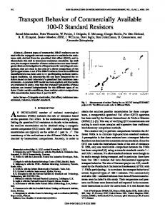
Fig. 1. The voltage calibration procedure used in NIST-1. Only Step 1 and Step 3 are used in NIST-10. The ground of the measurement circuit was at the return current side of the array bias supply.
problems when they occur, such as: array misbehavior; leftright effect between the digital voltmeter (DVM) and a large variety of Zener references under ac power; and sources of noise, such as thermal-emf drift, Zener reference failure, or DVM offset instability. The wiring schematic for the algorithm of NIST-1 is shown in Fig. 1 [3]. Equations (1)–(4) fully expand the voltages involved in the each step of four DVM (measurement time and order are signified with readings numerical subscripts 1–4), with DVM offset voltage , wire thermal-emf , and irreproducible switch contact (1) (2) (3) (4) has a related large noise . The Zener reference voltage are calculated from the step number , The array voltages microwave frequency , and the Josephson constant -
(5)
and are typically within 300 nV. They can be modeled as a linear drift plus a constant. The switch contact voltages are better modeled as four switch dependent values. is a noise function that can be reduced by taking a longer integration time. Assuming constant values for all voltages and neglecting the Zener noise, the average Zener value is (6) is an array value for a nominal . The average where can be calculated thermal voltages , and the DVM offset separately from (7) (8) At the high precision desired, however, these voltage sources are not constant, and even an assumption of linear drift over the total measurement time must consider additional noise terms. Often, switches or wires are not in thermal equilibrium and have exponential behavior. Thus, the additional demands on hardware for minimal offset drift are an attempt to limit the nonlinear contribution of these components.
The approach of programming in NIST-10 is to use a linear drift model and to reduce the strict four steps used in NIST-1 to two steps. In the NISTVolt procedure, only Step 1 and Step 3 shown in Fig. 1 are used. The time of each DVM reading is recorded. The DVM offset and thermal offset and their drifts are modeled by a combined offset and drift rate . The DVM readings are easily summarized as (9) or are chosen for Step 1 and Step where the sign 3, respectively, and is the elapsed time. Ten readings of the DVM for Step 1 are taken as the first data set. Then the polarity of the Zener reference and array are reversed and a second set of ten DVM readings is accumulated. The procedure is then repeated exactly. The NISTVolt program makes a linear fit to the 40 data points and calculates a best estimate of the Zener reference voltage, the combined offset, and the drift rate [4]. III. EXPERIMENTAL DESCRIPTION To check the complete hardware and software of these two systems, a comparison was started with the goal of obtaining a few nanovolts uncertainty at 1.018 V. Three Zener references were used to reduce the noise contribution. The original procedure reconnected the wires from each Zener to each system switch after several hours of automated measurements. The thermal-emfs of the individual connection wires were separately measured and subtracted from the array calibration values. However, the results from this procedure resulted in scatter of (20–30) nV. This was unacceptable, and it was apparent that the contact voltages of the automated scanners, normally within 50 nV, and the thermal-emfs of the connecting wires caused nonlinear offsets that were not cancelled to give the precision desired. Daily Zener noise is not linear at these voltage levels, so longer-term averaging was not possible. Therefore, an ultra-low thermal-emf switch was added to keep the Zeners connected with the same wires yet providing the necessary reversals, bypassing the automatic switching systems but still using the normal, programmatic reversal schemes for each system. This manual switch system is shown in Fig. 2. The polarity and interchange switches are commercial, double pole, multiposition switches. The thermal voltages of all the switch positions were measured before the experiment. The values
264
IEEE TRANSACTIONS ON INSTRUMENTATION AND MEASUREMENT, VOL. 48, NO. 2, APRIL 1999
Fig. 4. Calibration results of NIST-1 and NIST-10 for Zener reference 1.
TABLE I COMPARISON RESULTS OF THREE ZENER REFERENCES. THE UNIT FOR ALL NUMBERS IS MICROVOLTS. THE UNCERTAINTY BARS ARE THE TYPE A CONTRIBUTION ONLY Fig. 2. Manual switch system for comparing NIST-1 and NIST-10.
were grounded at the low potential side of the array bias supplies. Neither algorithm system displayed any left-right effect. During the actual measurements, neither of the input lines of the two systems were grounded. Both systems had the same external time base for the frequency counters. IV. RESULTS Fig. 3. Thermal voltages of the manual switch used in the intercomparison.
and fluctuations of the thermal voltages were within 3 nV. Fig. 3 shows a series of thermal voltage measurements for the manual switch. Both JVS systems share a switch for changing the polarity of a Zener reference and a DVM (for NIST-1 only). This arrangement adds the Zener voltage to the thermal voltage of the unreversed connecting wires. Thus, both JVS systems are measuring identical voltages with small additional fluctuations in the thermal voltages of the polarity switch. Each JVS system uses its own bias source, microwave source, frequency counter, and DVM. A total integration time of 5000 power line cycles ( 83 s) per reference value was selected to reduce high frequency Zener reference noise to several tens of nanovolts. The time between system interchanges of a single Zener reference was kept to within a few hours to avoid the long-term drift of the Zener reference and to minimize the impact due to changes in environmental conditions. Both systems use the same model high precision DVM to measure the voltage difference on a 100 mV range. Initially, Zener references 1 and 2 were connected to ac power when the measurements were made. Zener reference 3 was battery operated to check any effects due to ac power. The shield wires of both measurement circuits
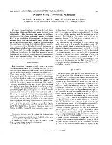
For even the most quiet hardware configuration, the noise of Zener references dominates at tens of nanovolts/volt electronic noise over periods of minutes to hours. Over several days the linear electronic drift becomes notable, while environmental influences, such as temperature, humidity, and atmospheric pressure begin to have greater nonlinear effects. Keeping the Zener references and thermal voltages as stable as possible and interchanging the Zeners between systems as quickly as possible were the key factors in achieving good results. The Zener references are in a stable temperature environment, controlled to 22 C with a standard deviation of 0.1 C at the time when the measurements were taken. The sequence of comparison measurements was interleaved in groups of three, two, and one in order to avoid effects due to Zener drift. Fig. 4 shows the results from NIST-1 and NIST-10 for Zener 1. The standard deviation of the mean of Zener 1 for the six measurements from each system was 4.0 nV. The individual uncertainty bars shown in the Fig. 4 are for the Type A contribution only. Table I lists the comparison results. Columns for NIST-1 and NIST-10 list the Zener reference difference from the nominal 1.018 V. The Delta column represents the difference between the two system calibrations of each Zener. Six measurements were averaged for Zener 1 and Zener 2 by each system, while nine measurements were averaged for Zener 3. The difference
TANG et al.: COMPARISON OF TWO JOSEPHSON ARRAY VOLTAGE STANDARD SYSTEMS
TABLE II STANDARD UNCERTAINTY COMPONENTS FOR NIST-1 AND NIST-10 AT 1.018 V. THE ESTIMATED TYPE B RELATIVE UNCERTAINTY FOR k = 2 WAS 2.6 nV/V FOR NIST-1 AND 4.4 nV/V FOR NIST-10 AT 1.018 V, RESPECTIVELY
265
linear voltage noise, as made in the calculation algorithms, are not as valid for offsets above about 25 nV. ACKNOWLEDGMENT The authors would like to thank C. Hamilton and J. Wang for their many helpful discussions and valuable assistance, and J. Kim (now at KRISS) for his contribution to the NIST-I program written in an icon-based instrumentation language. REFERENCES
of the combined average of the three Zener references with is nV. expanded standard uncertainty This indicates the equivalence of NIST-1 and NIST-10 system hardware and software under well controlled conditions. This is an improvement of about a factor of two on the results of a series of similar system comparisons performed in 1991 [2]. The comparison was repeated in a similar procedure with all Zener references under ac power. Each Zener reference was measured only three times by each system. The result of the nV . Type second test was a difference of B components of uncertainty for each system were analyzed independently, based on the slightly differing instrumentation, and are listed in Table II. The estimated expanded Type B was 2.6 nV/V for NIST-1 and 4.4 relative uncertainty nV/V for NIST-10 at 1.018 V. V. CONCLUSION It is recognized that there are error sources in a Josephson voltage standard system, so it is necessary to compare systems either directly or indirectly to have confidence in the system performance. However, it was difficult to reach an uncertainty of a few parts in 10 between NIST-1 and NIST-10, arising from the wire thermal voltages, nonlinear drifts, and irreproducible contact voltages of the switches typically used in these systems. A special switch system was then designed for an indirect system comparison at 1.018 V. Because the thermal voltages were reduced to nanovolt level and rapid interchanges made the Zener reference changes negligible, a highly precise and complete system comparison could be achieved. The fact that the system differences fall within combined the Type A and the Type B uncertainties of both systems helps to validate the Type B uncertainty analysis. Also, that it required such tightly controlled conditions to achieve nanovolt level scatter means that the assumptions about cancellation of constant or
[1] R. L. Kautz, C. A. Hamilton, and F. L. Lloyd, “Series-array Josephson voltage standards,” IEEE Trans. Magn., vol. MAG-23, pp. 883–890, Mar. 1987. [2] R. L. Steiner, A. F. Clark, C. Kiser, T. J. Witt, and D. Reymann, “Accurate comparisons of Josephson array systems,” IEEE Trans. Appl. Superconduct., vol. 3, pp. 1874–1877, Mar. 1993. [3] R. L. Steiner and R. J. Astalos, “Improvements for automating voltage calibrations using a 10 V Josephson array,” IEEE Trans. Instrum. Meas., vol. 40, pp. 321–325, Apr. 1991. [4] C. A. Hamilton, C. J. Burroughs, S. L. Kupferman, G. A. Naujoks, and A. Vickery, “A compact transportable Josephson voltage standard,” IEEE Trans. Instrum. Meas., vol. 46, pp. 237–240, Apr. 1997.
Yi-hua Tang received the Ph.D. in low-temperature physics from the University of Florida, Gainesville, in 1987. He worked in the private sector from 1991 to 1996 in the field of Josephson arrays and voltage standards. He joined the Electricity Division, National Institute of Standards and Technology, Gaithersburg, MD, in January 1997, and is working on the Josephson voltage standard and its applications in metrology. Dr. Tang is a member of the American Physical Society.
Richard Steiner, for a photograph and biography, see this issue, p. 208.
June Sims was born in Washington, DC, on April 3, 1952. She received the B.S. degree in electrical engineering from George Washington University, Washington, DC, in 1974. She joined the Electricity Division, National Institute of Standards and Technology (formerly the National Bureau of Standards), Gaithersburg, MD, in 1974, where she engaged in the development of automated voltage measurements at both high- and low-voltage levels. In 1981, she assumed responsibility for the operation of the NIST Volt Facility.