Composite Textures: emulating building materials and vegetation for 3D models Alexey Zalesny1 1
Dominik Auf der Maur1
Swiss Federal Institute of Technology Zurich, Switzerland 2 Catholic University of Leuven, Belgium
ABSTRACT In building 3D site models for visualization and virtual walkthrough, most emphasis so far has been on creating the 3D shape models. Less emphasis has been on creating realistic textures, e.g. to simulate building materials or vegetation. Nevertheless, the appearance of object and landscape models will depend at least as much on their textures, as on the precision of their geometry. The paper proposes a texture synthesis technique for the simulation of building materials and vegetation types. As textures can often more easily be described as a composition of subtextures than as a single texture, a hierarchical extension of our basic texture synthesis is proposed. These “composite textures” are based on a kind of metatexture concept, i.e. the layout of the different subtextures is itself modeled as a texture, that can be generated automatically. Examples are shown for building materials with an intricate structure and for the automatic creation of landscape textures. CR Categories: I.3.3. [Computer Graphics]: Picture/Image Generation. Additional Keywords: texture synthesis, texture analysis, statistical texture modeling.
1 REALISTIC VISUALIZATION OF ARCHAEOLOGICAL SITES: THE NEED FOR TEXTURE With the growing realism that computer graphics has to offer, there also is an increasing interest in the 3D modeling and visualization of archaeological sites. Such techniques hold enormous promise for both the public and the archaeologists. For the former, it means that a much more lively and enticing account of the living conditions in ancient times can be given. For the archaeologists, the 3D technology allows them to produce 3D 1
Luc Van Gool1, 2
D-ELEK/IKT, ETH Zurich, Switzerland {zalesny, aufdermaur, vangool}@vision.ee.ethz.ch http://www.vision.ee.ethz.ch/~zales +41 1 632{5724, 0714, 6578} 2 ESAT-PSI, Kath. Univ. Leuven, Belgium
[email protected] +32 16 321705
records of stratigraphy, to test for the validity of hypotheses on city architecture or on road and water supply networks, etc. This paper describes part of the work carried out under MURALE, an IST (Information Society and Technology) project funded by the European Commission with the goal to advance the use of computer technology in archaeology. The project puts much emphasis on the aforementioned 3D modeling and visualization and in particular, on creating tools that the archaeologists themselves can use in situ (and that they can afford). So far, much work went into the development of flexible technology for the creation of the 3D building and terrain models. This includes methods to measure up the existing 3D layout and shape of the ruins as well as methods to recreate their supposedly original state through CAAD. Apart from their shape, the patterns by which the models of buildings and terrain are covered - their textures - are at least as important for the creation of a realistic impression. Just like the developments in 3D shape modeling of the late 90s, one would also like to be able to do the modeling of textures solely from example images. This is the very goal of the work described here. This paper describes a texture modeling and synthesis method that works from example images of the target texture. Although the approach is generic, the particular goals here are to produce textures for the simulation of building materials and landscape vegetation. Building materials of which ruins have been constructed usually have undergone serious erosion and have lost their original appearance. Hence, it is useful if the original appearance can be simulated as a texture that is mapped onto the CAAD models of the buildings. This is obviously a more veridical visualization than just mapping the ruin’s texture onto the model. The same goes for the terrain model. The existing vegetation may be very different from that prevailing in the era for which a site model is produced. Rather than mapping the existing texture onto the terrain model, one would like to cover it with texture that simulates the vegetation of that era. Texture synthesis is not only useful to recreate appearances related to another period. Vegetation and landscape textures cannot always be photographed with sufficient resolution throughout the site to allow convincing fly-throughs. Mapping realistically looking landscape texture of an appropriate resolution onto the terrain model can solve that problem.
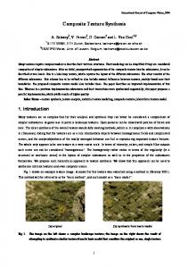
2 SAGALASSOS AS TESTING GROUND The MURALE project will focus its efforts on the archaeological site of Sagalassos, in what nowadays is Turkey. The site is lying about 100 km to the north of Antalya. The excavation in Sagalassos is one of the largest ongoing archaeological projects in the Mediterranean. The project is lead by Prof. Marc Waelkens of the University of Leuven. Sagalassos is lying at the southern flank of the Aglasun mountain ridge (western part of the Taurus-mountains) at a height between 1400 and 1650 meters. Figure 1 gives an overview of the site. In its day, it was one of the three most important cities of Pisidia.
Figure 1.
Overview of the Sagalassos site.
The city had thrived for about 1000 years, when it was finally abandoned after an earthquake in the 7th century AD. During this long period, it got under the military, political, and cultural influence of a series of foreign powers. In 333 BC the Sagalassons were defeated by Alexander the Great. Sagalassos was already an important city at that time. In the subsequent period it changed hands at several occasions between the successor kingdoms of Alexander’s splintered Macedonian empire. From 189 BC onwards, the Romans directly intervened in the region until in 133 BC it finally became formally part of the Roman state. In 25 BC emperor Augustus created the province of Galatia, which also incorporated Pisidia. It goes without saying that the city has changed substantially during this extended period, with its heydays around the 2nd century AD. MURALE will not be able to cover this whole evolution, and will focus on some selected periods. Changes were not only of a political nature, of course. Over time, architectural styles and techniques have changed, and so did the gamut of building materials that were at the builders’ disposal and that they preferred to use. Probably even more noticeable are the changes in vegetation found near the site in different periods. As can be seen from Figure 1, nowadays the mountain slopes are not covered by what one would consider an abundant vegetation (in contrast to the well-irrigated valley itself). They are covered by “thorn-cushion steppe”, a result of overgrazing. But at some point, the slope to the north of the city was at least partially covered by cedar woods, for instance. The first signs of human influence on the vegetation (anthropogenic pollen indicators) appear around 2000 BC. Human activity and its influence have increased since, with an expansion of open terrain at the expense of forest and with the large scale replacement of natural vegetation by agriculture and horticulture. This evolution is not monotonous though. For instance, during Hellenistic to middle Imperial times, indicators of anthropogenic activity decrease again. This may have had to do with the political unrest during the beginning of this period and the cutting of the enemy’s slow growing olive trees as part of standard warfare. Towards the end of Sagalassos’ existence as a living city, pollen finds show a pattern consistent with a return to pine forests and low level grazing, probably as a consequence of a reduced population. In
fact, much more detailed knowledge is available about how these factors changed during the centuries, thanks to thorough, multidisciplinary research within the scope of the Sagalassos project [7]. Hence, when one creates 3D models of the site, the choice of the right textures for the simulation of building materials and vegetation is an important one and depends on place and time. In summary, texture synthesis will be used for two purposes in MURALE: 1. mapping landscape (esp. vegetation) texture onto the terrain model of the site, where the texture is dependent on the chosen era (incl. modern times). 2. mapping building material textures onto 3D CAD models of buildings, simulating their state in the absence of erosion, or at different stages of erosion. That even modern landscape texture will be synthesized rather than photographed has to do with the resolution that would be required. One of MURALE’s goals is to allow a user to experience a virtual walkthrough of the site. The ruins are modeled on the basis of close-range photogrammetry techniques, whereas the overall terrain is modeled based on photographs taken from a long distance. As a consequence, there is a large discrepancy between the resolution of the texture on the landscape and the texture on the ruins. Although visitors can be expected to focus their attention on the ruin/buildings, the visual quality of the landscape texture in between should match that of the buildings. Otherwise, a disturbing, perceptual contrast appears, as shown in Figure 2. The resolution of the landscape texture does not match that of the ruin models (this is actually the case for both the geometry and the texture, but the geometrical aspect is not dealt with here and is less conspicuous). A way out would be to take more detailed pictures of the landscape texture throughout the complete area. This is not feasible however, as the site is tens of square kilometers in size. It would simply take too much time and memory, spent on non-essential information (not to mention that at some spots taking photographs would be a dangerous undertaking). There is no need to precisely capture every bush or natural stone. Thus, as a compromise we model the terrain texture on the basis of selected example images of real Sagalassos
texture. The terrain model is then covered with similar textures of the right type.
updated accordingly, and the statistical difference between the example texture and the synthesized texture is analyzed to decide which further addition to make. The set of selected clique types (from which textures are synthesized) is called the neighborhood system. The complete texture model consists of this neighborhood system and the statistical parameter set. The latter contains the joint probabilities for the selected relative, pairwise pixel positions. In fact we do not keep the complete, joint probabilities of colors at the clique pixels, but rather the histogram of intensity differences within and between the color bands.
Cliques of the same type
Cliques of different types
Figure 3. Dots represent pixels. Pixels connected by lines represent cliques. Left: cliques of the same type, right: cliques of different types.
Figure 2. View of part of a Roman bathhouse and surrounding landscape at Sagalassos. Top: view with the original landscape texture. As this is a view strongly zoomed in onto part of the landscape, the texture is of insufficient quality when compared to that of the ruin. Bottom: the landscape texture has been replaced by synthetic texture in the bottom right part of the scene. For all the applications of texture synthesis that were mentioned, a texture model is learnt from example images. The texture model is very compact and can be used to synthesize arbitrarily large patches of the texture. Section 3 describes the basic texture analysis and synthesis approach used for the relatively simple cases like this one. Then the paper moves on to the description of “composite textures” in section 4, which are used to deal with the synthesis of more complicated material and landscape patterns. Section 5 concludes the paper.
3 IMAGE-BASED TEXTURE SYNTHESIS A multitude of texture descriptions have been proposed in the literature, all with their pros and cons ([1], [2], [3], [4], [5], [6], [8], [11]). The approach proposed here is in line with the cooccurrence tradition, which seems to offer a good compromise between descriptive power and model compactness. Textures are synthesized as to mimic the pairwise statistics of their example texture. This means that the joint probabilities of the colors at pixel pairs with a fixed relative position are approximated as closely as possible. Such pairs will be referred to as cliques and pairs of the same type (same relative position between the pixels) as clique types. This is illustrated in Figure 3. The texture model consists of statistics for a set of different clique types. Just including all pairwise interactions (all clique types) in the model is not a viable approach and a good selection needs to be made [3]. We have opted for an approach that makes a selection as to keep this set minimal but that on the other hand brings the complete clique statistics of the synthesized textures very close to that of the example textures, i.e. also for these clique types that are not included in the model [9]. Clique type selection follows an iterative approach, where clique types are added one by one to the texture model, the synthetic texture is each time
A sketch of the texture model extraction algorithm is as follows: step 1: Collect the complete 2nd-order statistics for the example texture, i.e. the statistics of all clique types. After this step the example texture is no longer needed. As a matter of fact, the current implementation doesn't start from all pairwise interactions, as it focuses on interactions between positions within a maximal distance. step 2: Generate an image filled with independent noise and with values uniformly distributed in the range of the example texture. This noise image serves as the initial synthesized texture, to be refined in subsequent steps. step 3: Collect the statistics for all clique types from the current synthesized image. step 4: For each clique type, compare the statistics of the example texture and the synthesized texture and calculate their “distance”. For the statistics the intensity difference distribution (normalized histograms) were used and the distance was simply Euclidean. In fact, the intensity histograms pure were added also, where “singletons” played the role of an additional interaction. The current implementation uses image quantization with 32 gray levels. step 5: Select the clique type with the maximal distance (cf. step 4). If this distance is less than a threshold, go to step 8 – the end of the algorithm. Otherwise add the clique type to the current (initially empty) neighborhood system and all its statistical characteristics to the current (initially empty) texture parameter set. step 6: Synthesize a new texture using the updated neighborhood system and texture parameter set. step 7: Go to step 3. step 8: End of the algorithm. After the 8-step analysis algorithm we have the final neighborhood system of the texture and its statistical parameter set. A more detailed description of this texture modeling approach is given elsewhere [9]. In that paper it is also explained how the synthesis step works. In this section we demonstrate the use of this basic algorithm for the synthesis of Sagalassos textures, and in the next section we propose an extension towards “composite textures”, which we use for the synthesis of more complicated textures. In the case of Sagalassos, the method has mainly been used for colored textures. For the modeling of colored textures clique types
are added that combine intensities of the different color bands. The shortest 4-neighborhood system within the color bands and the interband interactions between identically placed pixels were always preselected because experiments showed that they are important for the vast majority of the texture classes. The proposed algorithm produces texture models that are very small compared to the complete 2nd-order statistics extracted in step 1 and also compared to the example image. Typically only 10 to 40 clique types are included and the model amounts from a few hundred to a few thousand bytes. Nevertheless, these models have proven effective for the synthesis of realistically looking textures of a wide variation. Another important advantage of the method is that – in contrast to some of the most interesting alternatives [1], [2] - it avoids verbatim copying, i.e. no pieces of the example texture are taken as such and spatially reorganized. Verbatim copying becomes particularly salient when large patches of texture need to be created. Then the repeated appearance of the same structures quickly becomes salient to the human eye. In our case we certainly have to produce extended texture patches. Verbatim copying would e.g. easily lead to the “same” stone or bush reappearing time and again in the landscape. This problem often not transpires very clearly from publications, as the extent of the texture that can be shown there has to be kept small in any case. Figure 4 shows a few examples for different building materials. The top row textures are example images of building materials (stone), used at Sagalassos. The bottom row shows the results of texture synthesis based on models extracted from the top row images.
travertine deposit (type 10) Figure 4.
limestone with chert nodules (type 3)
limestone breccia 1 (type 8)
visualizations one needs not only to add high quality models of objects that are missing, but also to remove those that represent anachronisms. A similar type of fill-in functionality also serves another purpose. It does not suffice to synthesize separate textures and build a collage from them. Where patches of different or even the same texture meet clear seams appear. Hence, a texture knitting tool was developed, that eliminates such sharp discontinuities. Consider Figure 7. The image on the left shows a composition of rock and grass texture images, both taken at Sagalassos. The right image shows the result obtained with the texture knitting algorithm. Knitting is based on learning a texture model from the zone around the border between the two textures. Then, new texture is generated in a zone around the border (not necessarily the same), based on the border zone texture model. In the case of a single texture, the seams between separately generated patches can be removed by simply applying that texture's own model near the border. As a matter of fact, in Figure 5 (d) such texture knitting was applied to the borders of the implanted cedar woods. The basic texture synthesis approach described in this section can handle quite broad classes of textures. Nevertheless, it has problems with capturing complex orderings of patches which themselves show textures (sometimes referred to as microtextures in the literature). This is why an extension towards a hierarchical approach – the “composite texture” idea proposed in the next section – is necessary.
limestone block with pink styloliths (type 1c)
marble from Dokimeion (type 6)
“white” crystallized limestone (type 5b)
limestone breccia 2 (type 8)
Example images of building material (top row) and synthetic textures based on models extracted from these examples (bottom row) (see color plates).
Figure 5 (a) and (b) show an example images for the texture of cedar woods. The corresponding texture model has then been used to plant virtual cedars on the mountain slope of the Sagalassos site, shown without them in figure (c) and with these trees on manually selected areas in figure (d). Figure 5 shows another interesting use of texture synthesis. The reader may have noticed that there addition of trees is not the only difference between images (c) and (d) in Figure 5. Several objects in the foreground have disappeared, like the blue crane with a car on the left and another car in the bottom-right part of the image. This was achieved by extracting texture models from the surrounding area, and by replacing the area occupied by these object by synthetic texture generated on the basis of these models. The areas concerned have been highlighted in Figure 6. These are the areas from which the texture models were extracted. Such ability to remove objects is interesting for virtual and augmented reality applications, as in order to create convincing
4 COMPOSITE TEXTURES Figure 8 shows part of the modern “thorn-cushion steppe” type of landscape found around Sagalassos (top). It consists of several ground cover types, like “rock”, “green bush”, “sand”, etc., for which the corresponding segments are drawn in the bottom figure. If one were to directly model this composite ground cover as a single texture, the basic texture analysis and synthesis algorithm proposed in the last section would not be able to capture all the complexity in such a scene. Therefore, a hierarchical version of the texture modeling approach is propounded, where a scene like this is first decomposed into the different composing elements, as shown in Figure 8 (bottom). The segments that correspond with different types have been given the same intensity (i.e. the same label). This segmentation has been done manually. Figure 9 shows the image patterns corresponding to the different segments.
(a)
(b)
(c)
(d) Figure 5.
(a) and (b) example images of cedar wood texture, (c) mountain slope behind Sagalassos in its current state, (d) virtual reforestation and irrelevant object removal (see color plates).
The textures within the different segments are simple enough to be handled by the basic algorithm. Hence, in this case 6 texture
models are created, one for each of the ground cover types (see caption of Figure 8). But also the map with segment labels (Figure
8 bottom image) can again be considered to be a texture, describing a typical landscape layout in this case. This texture is quite simple again, and can be handled by the basic algorithm. Hence, such layout textures or label textures can be generated automatically as well. The following idea then stands to reason: generate a composite texture, where first a landscape layout texture is generated. Subsequently, the different segments are filled in with the corresponding textures, based on these textures’ models. As an alternative, a graphical designer or artist can draw the layout, after which the computer fills out the textures in the segments that s/he has defined, according to their labels. Figure 10 shows one example for both procedures.
Figure 6. Areas from where texture models were learned to remove the objects in Figure 5 (c). Note that the bottom image has been created fully automatically and arbitrary amounts of such texture can be generated, enough to cover the terrain model with neverrepeating, yet detailed texture. As mentioned before, the fact that this approach doesn’t use verbatim copying of parts in the example images has the advantage that no disturbing repetitions are created.
Figure 8. Top: an example of modern Sagalassos texture, “thorn-cushion steppe”. Bottom: manual segmentation into basic ground cover types (also see Figure 9).
Figure 7. Example of texture knitting. Left: image comprising two types of Sagalassos texture, with rocks on top and grass below. Right: knitted rock and grass textures. A similar approach can be followed to generate textures of the more complicated types of marbles and limestones that were used as building materials. In a building like the Nymphaeum, for instance, about 10 differently colored stones were consciously combined to arrive at splendid color effects. If one wants to recreate the original appearance of this building and others in the monumental center of the city, such textures need to be shown with all their complexities and subtleties. Figure 11 shows an example of a limestone (pink-gray breccia) (a), which has a kind of patchy structure.
Figure 9. Manual segmentation of the Sagalassos terrain texture shown in Figure 8. Top: segments corresponding to 1green bush, 2-rock, 3-grass, 4-sand, 5-yellow bush. Bottom: left-over regions are grouped into an additional class corresponding to transition areas.
(a)
Figure 10. Synthetically generated Sagalassos landscape textures. Top: based on a manually drawn label map. Bottom: based on an automatically generated label map (see color plates). The different parts do not only have different colors, but also a substructure (microtexture) of their own. The overall breccia texture is too difficult to be modeled well by our basic algorithm, as shown in (b). This image is the texture generated from a single model. As for the landscapes, we can follow the composite texture approach. First, the original limestone image is manually segmented, whereupon texture models are generated for the different parts. An automatically generated, synthetic result is shown in Figure 12 (a). We can now drive the composite texture idea one step further and use it to simulate the evolving effect of erosion. By thresholding the image Figure 11 (a) the cracks and pits that are the consequence of erosion, can be isolated, as they correspond to black regions. The thresholded image again is a quite simple texture, that can be modeled on its own. Figure 12 (b) is the result of superimposing a synthetic erosion image onto image (a). A time series of erosion masks can be produced by applying an erosion operator (erosion in the mathematical morphology sense in this case) to the erosion texture, that has the effect of shrinking the black regions. Then one can start with the one that has the fewest black pixels as the initial level of erosion (in the geological sense, maximal erosion in the morphology sense). Figure 13 shows an example of the use of such texture. Our breccia texture has been superimposed on the lower part of one of the pillars of the Nymphaeum (the one closest to the viewer). It shows the contrast between the rather simplified texture that the graphical artist has used (upper part) in comparison to the kind of naturally looking textures that our method can generate.
(b) Figure 11. Pink-gray breccia. (a) original, (b) synthesized as a single texture (cf. Figure 12).
5 CONCLUSIONS AND FUTURE WORK We have described texture analysis and synthesis work within the MURALE project. In particular, we have focused on a texture synthesis method and its extension towards composite textures. This texture synthesis work is aimed at simulating the textures of building materials and vegetation types. In parallel, work is going on to synthesize textures with an appearance that differs with viewpoint and illumination [10]. An advantage of the methods is that they simply work from example images as input. In the case of composite textures, a segmentation has to be produced manually once. Hence, the efforts by the user are limited also in that case. Another advantage is that these methods are not based
on the verbatim copying of parts of the example textures. Such copies quickly become very salient as several of them appear in larger patches of textures. Moreover, the texture models are very compact and storage of the example images is not required.
ACKNOWLEDGEMENTS The authors gratefully acknowledge support from EU IST project “MURALE” and also wish to thank Axell Communication for making available their CAD model of the Nymphaeum.
Figure 13. Covering of the virtual pillar of the Nymphaeum with a synthetic pink-gray breccia texture from Figure 12 (see color plates).
REFERENCES [1]
J.S. De Bonet. Multiresolution Sampling Procedure for Analysis and Synthesis of Texture Images. SIGGRAPH 97, 1997, pp. 361-368.
[2]
A. Efros and T. Leung. Texture synthesis by nonparametric sampling. Proc. Int. Conf. Computer Vision (ICCV’99), Vol. 2, 1999, pp. 1033-1038.
[3]
A. Gagalowicz and S.D. Ma. Sequential Synthesis of Natural Textures. Computer Vision, Graphics, and Image Processing, Vol. 30, 1985, pp. 289-315.
[4]
G. Gimel’farb. Image Textures and Gibbs Random Fields. Kluwer Academic Publishers: Dordrecht, 1999, 250 p.
[5]
T. Leung and J. Malik. Recognizing surfaces using threedimensional textons. Proc. Int. Conf. Computer Vision (ICCV’99), 1999, pp. 1010-1017.
[6]
J. Portilla and E. P. Simoncelli. Texture Modeling and Synthesis using Joint Statistics of Complex Wavelet Coefficients. Int. J. of Computer Vision, Vol.40, No.1, pp.49-72, Oct. 2000.
[7]
M. Vermoere, L. Vanhecke, M. Waelkens, and E. Smets. Woodlands in Ancient and Modern Times in the Territory of Sagalassos, Southwest Turkey, to appear in: Sagalassos VI. Report on the survey and excavation campaigns of 1998, 1999, and 2000, ed. M. Waelkens, J. Poblome, Turnhout 2002.
[8]
L.-Y. Wei and M. Levoy. Fast texture synthesis using treestructured vector quantization. SIGGRAPH 00, pp.479-488.
[9]
A. Zalesny and L. Van Gool. A Compact Model for Viewpoint Dependent Texture Synthesis. SMILE 2000, Workshop on 3D Structure from Images, Lecture Notes in Computer Science 2018, M. Pollefeys et al. (Eds.), 2001, pp. 124-143.
(a)
(b) Figure 12. (a) pink-gray breccia (Figure 11) synthesized as a composite texture; (b) adding erosion, which was also modeled like an additional special type of texture (see color plates).
[10] A. Zalesny and L. Van Gool. Multiview Texture Models. Accepted for the CVPR 2001. [11] S.C. Zhu, Y.N. Wu, and D. Mumford. Filters, Random Fields And Maximum Entropy (FRAME). Int. J. Computer Vision, Vol. 27, No. 2, March/April 1998, pp. 1-20.
Color Plates
Alexey Zalesny, Dominik Auf der Maur, and Luc Van Gool. Composite Textures: emulating building materials and vegetation for 3D models.
Virtual reforestation of Sagalassos with cedar wood and irrelevant object removal. (Alexey Zalesny, Dominik Auf der Maur, and Luc Van Gool. Composite Textures: emulating building materials and vegetation for 3D models).
Marble and limestone synthesis (top). Complete scene synthesis (middle). Composite texture synthesis with erosion simulation and covering of the virtual pillar (bottom). (Alexey Zalesny, Dominik Auf der Maur, and Luc Van Gool. Composite Textures: emulating building materials and vegetation for 3D models).