Normally, spherical segments are used because they give better thickness ... setup, we develop a method to obtain optimum layer thick- ness uniformity between ..... thickness distribution over the different substrates of a single sector, choosing ...
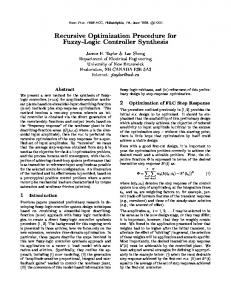
Computer-aided procedure for optimization of layer thickness uniformity in thermal evaporation physical vapor deposition chambers for lens coating Salvador Bosch Departament de Flsica Aplicada i Electronica, Universitat de Barcelona, Diagonal 647, 08028 Barcelona, Spain
(Received 27 March 1991; accepted 14 September 1991) A computer-aided method to improve the thickness uniformity attainable when coating multiple substrates inside a thermal evaporation physical vapor deposition unit is presented. The study is developed for the classical spherical (dome-shaped) calotte and also for a plane sector reversible holder setup. This second arrangement is very useful for coating both sides ofthe substrate, such as antireflection multilayers on lenses. The design of static correcting shutters for both kinds of configurations is also discussed. Some results of using the method are presented as an illustration.
I. INTRODUCTION Technical production of thin film coatings for lenses requires the use of big high vacuum evaporation plants in order to simultaneously coat a large number of lenses. Nevertheless, it is necessary to obtain sufficient uniformity in the deposition of materials over all the substrates being coated. For this purpose, in physical vapor deposition (PVD) using crucibles or electron beam guns, lenses are held on suitable palettes which are rotated with respect to a vertical axis passing through the center of the chamber while the evaporation is carried out. Normally, spherical segments are used because they give better thickness uniformity than plane palettes. To increase the final uniformity, static correction shutters of appropriate position, shape and size must be designed. Other major factors to obtain good thickness uniformity are (a) to locate the evaporation source at the best radial distance from the center of the chamber; (b) to carefully monitor the evaporation rate, keeping it as uniform as possible in order to maintain the shape of the vapor cloud emitted from the crucible. In many practical applications it is necessary to coat both sides of the substrates, e.g., broadband antireflection treatments on lenses. Thus, a further improvement for industrial purposes is to coat the two surfaces without opening the vacuum chamber. This greatly reduces the total process time and there is therefore increasing interest in reversible substrate holders. These usually consist of several (7 or 8) plane sectors assembled (at a certain angle) over a central axis (see Fig. 3). Using this equipment, the coating of one side is made while the whole setup is rotating around the axis of the chamber. Then, the evaporation process is stopped, the plane sectors are turned upside down and the other substrate side is similarly coated. Although this setup may be built in such a way that it is closely adapted to the shape of a spherical segment spatial distribution, the lack of rotational symmetry makes a perfect thickness uniformity mathematically impossible, even using correcting static shutters during evaporation. From a practical point of view, the limiting thickness uniformity when coating a large number of substrates using standard industrial high vacuum equipment is about ± 1%.1 We will take 98
J. Vac. Sci. Technol. A 10 (1), JanlFeb 1992
this thickness uniformity as our practical limit. Moreover, it may be considered optimal when dealing with antireflective (AR) coatings involving several layers in the 100 nm range. In this work, after a particular study of the geometrical arrangement corresponding to this reversible plane sector setup, we develop a method to obtain optimum layer thickness uniformity between the different coated substrates. The method will be useful both for the spherical and plane-sectors calotte. The geometrical study will take into account the influence of the shape of the vapor cloud emanating from the source and will allow the design of static correcting shutters for final thickness optimization.
II. GEOMETRICAL RELATIONS Let us deduce the basic equation for all the computation methods that will follow. We shall assume that the evaporation source may be considered as a single surface element dS (see Fig. 1) emitting towards the upper-half space in such a way that its emissive power depends only on the angle a with respect to its perpendicular direction. We shall take this dependence as directly proportional to the value cos n (a), n being a value that depends on the evaporation conditions (material, type of crucible, applied evaporation power, etc.).1 Moreover, the source will be horizontal, i.e., the angle a will always be measured with respect to the vertical direction. The supposition concerning the size of the source could be refined, but for a big PVD unit where the distance from the source to the substrates is almost 1 m, it is enough to consider the crucible or electron beam gun as a single surface element. The emissive characteristics of the source may also be slightly refined by introducing the isotropic component of the distribution, A, which changes the angular dependence to (1 + A) cos n (a) + A, 1 but the practical results obtained are similar to our simpler model. A surface element to be coated dA (Fig. 1), at a distance d from the source and with its normal forming an angle (3 with the line dS-dA, will subtend (from dS) a solid angle dw = dA cos «(3) / d 2. Then, the amount of evaporated material deposited onto the surface element dA per unit time is
0734-2101/92/010098-07$01.00
© 1992 American Vacuum Society
98
99
Salvador Bosch: Thermal evaporation PVD chambers for lens coating
99
z
dA FIG. 1. Elementary geometrical configuration.
dS h
(1)
where K is a constant value that may also include the sticking coefficient between substrate and material. All practical PVD configurations can be treated as a process of many differential depositions dm with the same value K, provided the evaporation rate is maintained. The remaining problem is to adequately describe the simultaneous variations of d, a, {3, ... as the evaporation process is taking place. Two main configurations are interesting: spherical segment substrate holder (dome-shaped calotte) and plane sector reversible holder, both rotating with respect to a vertical central axis during evaporation. The first is known to be far superior to plane holders. 1,2 The second setup allows the coating of the two sides without opening the chamber. Of course, we need only to compute the thickness deposited at a single holder turn, because all depositions take place with the holder rotating and differences between successive turns are only expected when evaporation rate monitoring fails. Finally, it is important to notice that our supposition concerning the a priori knowledge of the exponent n is not realistic. From a practical point of view, the operating method will be to compare the expected thickness values for different exponents n with the experimental measurements of samples coated with a well known geometrical arrangement (using the numerical methods explained below). This comparison will enable us to deduce the emissive characteristics of the source under our evaporation conditions. Moreover, the value n is taken to be constant during layer deposition, neglecting variations due to the reduction in the amount of evaporation material, for example. This practical procedure is mainly justified because of the assumed constant evaporation rate (well monitored) and also by the use of new and equally well filled crucibles. The remaining variations in n may be considered a secondary effect, as we are dealing with + 1% thickness accuracy within layers usually thinner than
loooA.
A. Dome-shaped (spherical) calotte
This evaporator geometry has been studied elsewhere. 1 The basic configuration is shown in Fig. 2. The setup is fully defined by the height h, the radius of the dome ( OR = PR ) and the position of the evaporation source Q. With respect to expression ( 1), the angles a and (J are shown and d = QP. Using the mathematical expressions given in Ref. I it is possible to evaluate the thickness deposited at any J. Vac. Sci. Techno\. A, Vol. 10, No.1, Jan/Feb 1992
~
________~__- L__. .
y
x FIG. 2. Diagram of the dome-shaped calotte.
radial position P of the substrate holder during any variation in angle qJ. This may be used to optimize the position of the evaporation source and to design the static correcting shutters for optimum thickness uniformity. All the substrates placed on the calotte at the same radial distance from the rotation axis (Z) are equivalent. This implies that, from the mathematical point of view, the perfect thickness uniformity would be attained using a well designed static correcting shutter during evaporation. B. Plane sectors reversible holder
The sketch of this setup is presented in Fig. 3(a). Let us designate by l) the angle between the rotation axis and the plane of an individual sector. Notice that, after the coating of one face and before the second one, the sectors will be turned upside down around the axis ON. For this configuration, the position of the substrate cannot be defined only by its distance from the rotation axis. A method to compute the thickness received by each point of one sector of the holder is developed in the following. Let us define [see Fig. 3 (a)] the position P of the receiving element dA by the distances PN and NO, all measured over the plane of the sector. Taking the evaporation source dS placed at a point Q on the X axis, when the rotation of the sector is defined by qJ, we have for the terms in expression (1) ~
---......
-
a= Q'QP, {3= QPR, d= QP,
Q being just any point above Q and R any point on the normal to the sector through P. A further refinement can be incorporated in the computer program: to include the case of an imperfect sector reversion (which will be useful for comparison with experimental resuits). We may admit that a line lying on the plane of the sector and perpendicular to the axis ON may not be horizontal [Fig. 3(b)] but tilted by a small angle 6. For this more general case the true receiving point Pcorresponds to a nontilted case point P'. Once the distances NO, PN == P'N I
100
Salvador Bosch: Thermal evaporation PVD chambers for lens coating
z
1T
100
< cp < 21T give different deposited thicknesses, even when
() = O. This is easily proved by computing both half cycles or
o~
noting the nonequivalent progressions of angle {3. Of course this is not the case for the spherical sector. Following the mathematical approach given above, one may readily develop computer programs to estimate the relative thickness deposited in any point of either the spherical or the plane-sectors calotte, corresponding to any change in the rotation of the holder (defined by the limiting angles cp , and cp"). It is apparent in this development that we do not take into accoun~ the curvature of the surfaces of the coated lenses, assuming plane substrates lying tangentially to the holder. It would be easy to show that this curvature greatly influences the thicknesses deposited, since it greatly changes the angle {3. Nevertheless, as the thickness over a particular substrate (lens) may not be optimized with our general methods (intended for the whole calotte) and the curvatures have a wide range of variation (from concave to convex), it would be only of mathematical interest to deal with nonplane substrates.
______~_.-
Q'
.-"'