Context adaptive binary arithmetic decoding on transport triggered architecture Joona Rouvinena , Pekka J¨a¨askel¨ainenb , Tero Rintaluomac , Olli Silv´ena , Jarmo Takalab a University
b
of Oulu, Oulu, Finland Tampere University of Technology, Tampere, Finland c On2 Technologies, Oulu, Finland ABSTRACT
Video coding standards, such as MPEG-4, H.264, and VC1, define hybrid transform based block motion compensated techniques that employ almost the same coding tools. This observation has been a foundation for defining the MPEG Reconfigurable Multimedia Coding framework that targets to facilitate multi-format codec design. The idea is to send a description of the codec with the bit stream, and to reconfigure the coding tools accordingly on-the-fly. This kind of approach favors software solutions, and is a substantial challenge for the implementers of mobile multimedia devices that aim at high energy efficiency. In particularly as high definition formats are about to be required from mobile multimedia devices, variable length decoders are becoming a serious bottleneck. Even at current moderate mobile video bitrates software based variable length decoders swallow a major portion of the resources of a mobile processor. In this paper we present a Transport Triggered Architecture (TTA) based programmable implementation for Context Adaptive Binary Arithmetic de-Coding (CABAC) that is used e.g in the main profile of H.264 and in JPEG2000. The solution can be used even for other variable length codes. Keywords: CABAC, H.264, MPEG4, multi-format codec design, TTA, variable length codes
1. INTRODUCTION Digital convergence has made the contents of the Internet accessible via handheld wireless mobile communication devices, which means that a large number of the available video coding formats need to be supported. In practice, the users will expect the capability to view a full length movie without connecting to the mains. This makes energy efficiency a prime design challenge of system level. A practical limitation for the usage time of a handheld device comes from the maximum tolerated power dissipation that is approximately 3W. If this is exceeded for a 100cc device, it becomes too hot to handle. However, in order to view a three hour movie, the 3W power consumption would require at least a 2500mAh 3.6V LiON battery that will be unrealistic in a small device at least for the next few years. We may expect the small devices to employ batteries at most half that capacity, pushing the power dissipation limit to approximately 1-1.5W of which at most 100mW can be used for application processing such as video decoding. Table 1 depicts the characteristics of expected handheld devices together with the power breakdowns of an early 3G cellular phone and a Personal Digital Assistant (PDA) device.1 We observe that the power needs of the RF and baseband are expected to remain at a constant level. This is explained by the increasing data rates and complexity of the baseband signal processing. The biggest expected power efficiency changes are in the display solutions due to the emerging organic technologies and in application processing. However, application processing can not rely on the improving energy efficiency of conventional programmable processors, although these would be the most convenient means to support multiple video standards in the same device. Table 2 shows the power needs of two ARM processors and an Intel processor in decoding 30 fps VGA (640 x 480 pixels) H.264 bitstreams.1 Clearly, software solutions are power hungry. While hardware acceleration can be more efficient, it is inflexible, when support for multiple standards is needed. Further author information: (Send correspondence to Joona Rouvinen.) Joona Rouvinen.: E-mail:
[email protected]
Table 1. Power consumption characteristics of the expected handheld devices.
System component Application processor and memories Display, audio, keyboard and backlights (UI) Misc. memories
3G phone in video streaming mode (mW) 600
PDA device in MPEG-4 playback (mW) 840
1000
2510
200
670
RF and cellular modem
1200
N/A
Total
3000
4020
Battery Capacity /usage time
1000mAh/1h
N/A
Interestingly, the popular video codecs, for example, MPEG-4,2 H.264,3 VP6,4 and VC-1,5 all define hybrid transform based block motion compensated techniques that employ mostly the same coding tools. This observation has been a starting point for the defining MPEG Reconfigurable Multimedia Coding (RMC) framework that targets to facilitate multi-format codec design. The idea is to send a description of the codec with the bitstream, and to reconfigure the coding tools accordingly on-the-fly. Apparently, this kind of approach favors the flexible software solutions, and is a big challenge for the implementors of mobile multimedia devices that need to rely on hardware acceleration and functionally pipelined computing. One proposed hardware architecture for RMC has bee presented by Hsiao and Tsai.6 Here we present an application specific programmable processor solution for variable length decoding. The processor technology used here is based on the Transport Triggered Architecture (TTA) principles.7 TTA approach was chosen because, based on our experience, it is possible to gain good energy efficiency while maintaining the flexibility needed in RMC. The approach is demonstrated for Context Adaptive Binary Arithmetic de-Coding (CABAC) that is used in the main profile of H.264 and JPEG2000. However, it can be used even for other variable length codes. Table 2. Power needs of selected processors in H.264 decoding.
Device
CMOS process
Bitrate kbit/s
ARM10(1022E) ARM11 (1136J-S) Core Duo (Yonah)
90nm 1V 90nm 1V 65nm 1.33V
512 512 470
Power consumpition in (mW). 222 332 3160
2. ORGANIZATION OF A MULTI-STANDARD VIDEO DECODER. Fig. 1 shows the logical organization of a hardware accelerator for multi-standard video decoding. The functional blocks need to support the specific coding tools and their variants of each standard. For simplicity, the control has been omitted from the figure. When new standards are added the finite state machine control of the accelerator becomes more and more complicated. From the video decoding throughput point of view the variable length decoding stage is a critical one as its algorithms are a very significant differentiator between standards, and even their profiles. Table 3 shows some of the most popular codecs and their entropy coding methods. As the variable length decoding usually demands bit serial processing, this stage becomes a bottleneck, when high definition formats are required from mobile multimedia devices. Context-based Adaptive Variable Length Coding (CAVLC) used in H.264 Baseline
Inverse Transform Entropy decoding DCT CABAC HADAMARD CAVLC
IN
De-quantize
INTEGER
+
HUFFMAN
Frame Reorder
OUT
Some other transform
EXP-GOLOMB
ARITHMETIC
Transform Coeffients Prediction decoder VC-1
Motion Predictor H.264 Motion Predictor MPEG4 Motion Predictor VC-1
Prediction decoder H.264 Prediction decoder MPEG4
Reference Frame Store
Motion vectors
Figure 1. The logical organization of a hardware accelerator when multiple standards are supported.
profile is an improved version of the variable length techniques used in earlier standards. It is a lower-complexity alternative to CABAC for the coding of quantized transform coefficient values. Instead of fixed code tables, the tables of CAVLC are modified according to the context.8 Variable Length Coding (VLC) is usually implemented with fixed tables and Huffman coding. Table 3. Some of the popular codecs and their entropy coding methods.
Codec
Entropy coding method
H.264
Exp-Golomb, CAVLC, CABAC
VC-1
Multiple VLC tables
VP-6
Arithmetic and Huffman coding variants
MPEG-4
VLC, arithmetic coding
MPEG-2
Multiple VLC tables
Pure software solutions are not attractive for variable length decoding, because the computational costs can grow significantly when higher resolutions and bitrates are used. For example, CABAC decoding for VGA 30fps 512kbps H.264 video bitstream demands 120 - 130 MHz on a ARM9 processor. This is almost twice the clockrate needed for CAVLC. The benefit is 9 to 14 % lower bitrate.10 It is obvious that hardware acceleration or application specific instructions are needed to achieve the necessary efficiency. It has been shown that it is possible to accelerate CABAC to even as fast as 1 cycle/decoded symbol. However, a programmable solution based e.g, an application specific instruction set processor (ASIP) can be an attractive alternative, despite the lower performance. In this paper we have taken the primary goal to develop a programmable solution. Although decoding speed is important, at this point our main interest has been to develop solution that can support different variable length codes with the same hardware resources, as that can contribute to lower static power consumption due to smaller silicon area.
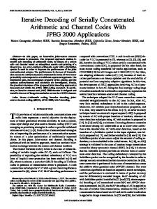
3. ARITHMETIC CODING Shannon’s theoretical limit cab be used to determine the information content of a message. The minimum number of bits needed is −log2 P (symbol) for each symbol with probability P (symbol). For P (0.5) the result would be 1 bit, as one would assume, but the result can also be non-integer. For example, if the probability of a symbol is 1/3, the optimal number of bits would be around 1.6. However, the popular Huffman codes have to be an integral number of bits long. This leads to longer code than would be theoretically possible.9 Arithmetic coding can code symbols using also non-fractional number of bits. This is because the whole message is encoded into a single codeword instead of separate encoded symbols. For this reason, arithmetic coders can produce results close to Shannon’s theoretical information limit. It also allows the efficient direct use of the arithmetic coding when there are only two symbols, like 1 and 0, because it is not needed to build larger supersymbols before encoding a word. The arithmetic coding is based on dividing coding range into subranges based on the symbol probabilities. At the decoder end, if the symbol probabilities are known, the message can be explicitly interpreted from the encoded fractional number. Fig. 2 illustrates the basic principle of arithmetic coding. In this example there are four symbols, A, B, C and D with probabilities PA = (0.5), PB = (0.25), PC = (0.125) and PD = (0.125). So the message A B C D would be coded into an interval between 0.357421875 and 0.359375000. This resulting interval identifies the sequence of symbols that produced it, but the decoder does not need the whole interval. It is necessary to transmit only one fraction with enough digits so that those digits fall into the final interval. In this example 0.358 would be enough. With these digits of the fraction and the model used one can reconstruct the symbol sequence that entered to the encoder. In this example the symbol probabilities were chosen so that P (symbol) is a negative power of two for all the symbols and because of this −log2 P (symbol) produces only integers. This makes also Huffman coding optimal, but this is only a special case.
Figure 2. Arithmetic coding is based on interval subdivision according to the symbol probabilities.The original range is divided relative to the symbol probabilities, so if the first symbol would be A, the new range would be between 0.0 and 0.5, which would again be divided to sub ranges according to the original symbol probabilities.
3.1 Practical implementations In practical solutions, when arithmetic coding is implemented with fixed size registers, the needed infinite precision is not available. In practice, it is best to implement arithmetic coding with fixed point integer math, using 16 or 32 bit fixed point computing, as floating point math is neither required or helpful.9 So, fractions are rounded to their nearest equivalent integers and two integer numbers are used to represent the range. When integers are
used to represent the range, it has to be renormalized, when values for the lower and higher part of the range are too close to each other. This is to ensure that there is enough precision for the next subdivision. At the binary arithmetic encoder, renormalization is done by shifting out bits, which represent the encoded symbols. Then new bits are added to expand the range as wide as possible.
4. CONTEXT ADAPTIVE BINARY ARITHMETIC DE-CODING A practical problem with the arithmetic coding is that both the encoder and decoder need to know the symbol probabilities. Some of the channel capacity is needed for transmitting this information. However, it is possible to avoid the need to send the probabilities, if the coding is done adaptively. In this scheme the encoder and decoder adapt the symbol probabilities according to the rate they appear. This is convenient, if there is no good advance model available of the symbol probability distribution, or if the data type changes at some point. It is important to notice that entropy coding is efficient only as long as the probability model used is close enough to represent the real rate of the appearance of a symbol to be coded, 1 or 0 in the case of binary arithmetic coding. If the model is unsuitable, the performance penalty can be huge. Together with adaptation to the rate the symbols appearing, the coding can be even more efficient, if the symbol probabilities are adapted also to the data that they represent. This makes the probability model more precise. In other words, context adaptive solutions provide better compression efficiency, as they construct a statistical model according to the context of the current syntax element being encoded or decoded. The context is the type of data, like motion vectors, transform coefficients etc. CABAC in H.264 uses very sophisticated models for different types of data with 399 different contexts. Through this approach, compared to the baseline entropy coding method of H.264, CABAC reduces the average bitrate by 9 to 14 %.10
4.1 CABAC in H.264 In H.264, picture may be divided into one or several slices. Each slice is a sequence of a 16-by-16 pixel macroblocks when Flexible Macroblock Ordering (FMO) is not used.3 One example of a picture divided into three separate slices is represented in Fig. 3. Macroblocks are marked with dotted lines. In H.264 a slice can be decoded independently and the arithmetic coding engine resets itself before the beginning of a slice. The context information of the previous syntax elements is not needed to start decoding a new slice.
Figure 3. Slice structure of a frame in H.264 bitstream.
Some of the symbols are also coded and decoded in so called ”by-pass mode”, which is computationally less demanding. This is done when the symbols have uniform probability distribution. In this case there is nothing to gained by using arithmetic coding. Although the number of transmitted bits is not reduced, arithmetic coding can still be done in a computationally lighter way.
4.2 Computation of CABAC This section presents the computation flow of CABAC3 from the H.264 standard. In binary arithmetic decoding there can be only two different symbols. In H.264 they are called most probable (M P S) and least probable symbol (LP S). Their names indicate the amount of the probability mass they have, when the decoding decision is made. M P S and LP S can be 1 or 0. The decision whether M P S is 1 or 0 depends on the current statistical
model. The principle of the decoding decision is illustrated11 in Fig. 4. The probability model also defines the state, which rules the division of the range to M P S and LP S regions and guides the symbol decision that is made based on the value. The division of the range is calculated using table look-up for rLP S value in order to reduce the computational burden.
Figure 4. Illustration how the decicison to produce 1 or 0 is made.
The flow diagram of the CABAC algorithm is represented in Fig. 5, modified from the official ITU recommendation. The algorithm goes as follows: 1. Get the updated probability model (Values for M P S and state). 2. Fetch value for rLP S from the predefined table. Calculate new range = range − rLP S and compare the current value for this new range (see Fig. 4). If the value is bigger than range − rLP S, then the next symbol is LP S, if the value is less the the next symbol is M P S. 3. In LP S case the value has to be recalculated because the zero point of the range changes and it becomes value − range − rLP S. The new range becomes rLP S. If necessary (current state is equal to zero), the meaning of M P S is changed. The next state is updated from table, LP SnextState. 4. In M P S case the value remains the same, next state is updated from table M P SnextState and the new range becomes range − rLP S. 5. Check if the current range is smaller than rangeorig /4. If the current range is too small it is renormalized (shifted left by one) and new bit is read from bitstream∗ to keep the value up to range. Repeat if needed. There are 64 different values to represent the state of the probability model, which depends on the symbol distribution and current context. The next state calculated by the arithmetic decoder does not necessarily have to be the next state returned to the decoding engine on the next iteration. It can be, but it can also happen that the probability model changes because the data type changes. This is the context adaptiveness. The arithmetic decoder core handles only bits, not complete syntax elements and does not ”know” what is taking place in the other parts of the codec.
4.3 Implementation costs of CABAC The software implementation costs of CABAC consist mostly from the multiple sequential memory operations and from the renormalization process, implemented by a while-loop. The need to implement an effective decoder without the computationally heavy multiplication for every decoded symbol was recognized already in the standardization phase, and the multiplication can be avoided by table look-up approximation as explained. CABAC is a demanding algorithm to optimize from a software point of view. The instruction level parallelism is severely limited due to data dependencies and there are conditional branches in the control flow. The symbols ∗
This is where the decompression process can be seen clearly, the algorithm produces one bit every iteration but does not necessary read bits from the input stream every iteration.
Get the probability model (values for state and MPS)
1
fetch value for the rLPS from static table according to state and current range. Calculate range -rLPS
2 YES
No Is value > range -rLPS ?
LPS
MPS
calculate new value because zero point changes. new range is range - rLPS
YES
3
is state zero?
get next state from MPSnextState table new range is rLPS
4
Change meaning of MPS
No Renormalization process
get next state from LPSnextState table
range < (orig. range / 4) ?
No
5 YES
shift range left and read new bit to value
Done
Figure 5. The H.264 CABAC decoding process.
also need to be decoded one by one, as we need the value of the previous decoded symbol to decode the next one. Because the CABAC decoder is the first block of the video decoder, it can be a bottleneck for the whole implementation. A software solution could perhaps run faster with some type of speculative execution or by using predicated execution to get rid of the branches, which restrict the parallelization of the code by a compiler. However, with a normal application-specific instruction set processor (ASIP) we would need aggressive optimization and dedicated hardware for special CABAC operations to make the decoding run fast enough. If there would not be the need to support different entropy coding algorithms, the CABAC decoding would be reasonable to implement with a finite state machine controlled hardware accelerator, if higher resolutions are used. A set of interesting instruction set extensions to accelerate CABAC on a general digital signal processor (DSP) have been proposed by Flordal.12 The most interesting one is a multi-branch instruction to accelerate the control flow by calculating multiple branching steps in one cycle. The Million Instructions Per Second (MIPS) costs of an H.264 CABAC encoder can be seen13 in Table 4. Although these results are for the encoder they should give a good approximation for the costs of the decoders. The difference between an ASIP solution and a pure hardware accelerator is quite dramatic. This makes application specific processor (ASP)† architectures, †
Terms ASP and ASIP are used often quite freely but there is a difference. During the design time, ASP allows the customization of all the processor resources, while ASIP allows only the modification of the instruction set.
Table 4. Approximate MIPS cost at various resolutions at 30 fps. Bitrates are less than 0.5 Mbps for QCIF, 1 Mbps for CIF, 3 Mbps for 4CIF and 10 Mbps for HDTV.
QCIF
CIF
4CIF
HDTV
Software on DSP
14
29
87
290
ASIP
10
21
63
210
Accelerator
1
2.3
8
23
which land in the middleground between dedicated hardware and ASIP, interesting. There are also some ASIP type commercial processors available tuned for H.264 CABAC. For example, Philips TM3270 is very long instruction word (VLIW) Media Processor14 with support for two-slot operations allowing more input and output operands. It contains instruction enhancements targeted to the multimedia and video coding area and it has support for H.264 CABAC. With two new CABAC-operations the speed-up in the decoding process is measured as 1.5-1.7 VLIW instructions/decoded bit. Clearly, this is in the same range as the speed-up when moving from software on DSP to ASIP as illustrated in Table 4.
4.4 Hardware solutions Hardware solutions can radically speed up the CABAC algorithm by using tools like predictive execution and advanced pipelining. In principle, these could also be employed in ASP. In their solution Eeckhaut et al11 have optimized the critical path through both the model selector and the arithmetic decoder. The critical path through the model selector can be kept short by calculating every possible next model in advance. Because there are only two possibilities for the next symbol, 1 or 0, there can be only two different models. At the time the bit to be decoded is known, the right model is then simply selected. The critical path in the decoder engine is optimized by speculatively prefetching and caching the data to reduce memory operations needed to decode a bit. The redrawn block diagram of this solution is presented in Fig. 6. Three tables rLPS, NextStateLPS and NextStateMPS are implemented in simple ROMs. The advantage is effective pipelining.
Figure 6. Block diagram of an arithmetic decoder solution redrawn.11
The renormalization process is optimized by using leading zero anticipation (LZA). The original process that shifts range and reads in one bit if the range is smaller than rangeorig /4 has been replaced by this algorithm. This is based on the fact that the number of needed iterations corresponds to the number of leading zeros. This means that it is possible to eliminate the non-deterministic renormalization loop. The results are very good, as this arithmetic decoder core can decode 1 symbol/cycle, while the whole solution can decode 70 million symbols/s when synthesized for Altera Starix S25 (C5). This is enough for high quality HDTV. The schematic of the solution11 is represented in Fig. 7.
Model M
Stateisnotzero(M,nm)
value (n)
MPS ( M,nm)
rLPS(M,nm) range(n)
LZ
LZA
stateMPS(M,nm+1)
stateLPS(M,nm+1)
ADD NOT
ADD
> NOT
MUX
NAND
MUX
MUX
MUX
MUX Resultbit(nM)
=MPS? MUX
Symbol Buffer Shifter
Shifter
value (n+1)
range(n+1)
MPS(M,nm+1)
OR
Used to fetch data in cycle (n+1) for next occurence of model M, this data is written back in cycle (n+2)
state(M,nm+1
stateisnotzero(M,nm+1
Model Q
Stateisnotzero(M,n)
value(n+1)
MPS(Q,nq)
rLPS(Q,nq)
range(n+1)
stateMPS(Q,n+1)
stateLPS(Q,n+1)
Figure 7. Schematic of the calculations, originally represented by Eeckhaut et al,11 for decoding a result bit (nM ) with model M . For clarity, the schematic has been simplified from the original publication.
It is clear that a very fast CABAC decoder can be realized with dedicated hardware. The problem is how to use these results in a programmable solution, without making it too CABAC specific.
5. TRANSPORT TRIGGERED ARCHITECTURE IMPLEMENTATION OF CABAC The designed TTA processor is targeted to support multiformat variable length coding, with the main effort being on accelerating the CABAC. This section describes the used processor architecture and the resulting design.
5.1 Transport Triggered Architectures Transport Triggered Architecture (TTA) is a modular ASP architecture template that allows easy customization of the processor resources.7 The TTA concept is derived from VLIW, the main improvement being the decoupling of the register files and function units by means of a programmer-visible interconnection network. This special feature of TTA supports datapath operations with an arbitrary number of inputs and outputs, and adding function units to the processor datapath without dramatically increasing the register file or bypass network complexity. The structure of an example TTA architecture is represented in Fig. 8. TTA processors are built of independent function units (FU) and register files (RF), which are connected with transport buses and sockets. FUs may perform simple arithmetic and logic operations or they may be targeted for some application specific task (so called special function units, SFUs). Additionally, the interconnection network and the register file resources can be customized for each processor according to the application requirements, in contrast to VLIW where the number of register file ports and the bypass network must be dimensioned for the worst case when all FUs simultaneously read their inputs and write their outputs to the register files. TTAs are programmed by defining data transports between the register files and function units. This type of fine-grained programmability enables additional optimizations to be peformed by the compiler such as software bypassing, operand sharing, and more scheduling freedom in general.15 However, the additional scheduling freedom can be seen also as a drawback of TTAs as it complicates the instruction scheduler implementation somewhat.
RF
FU
FU
CNTRL
IMEM
Input socket interconnection network
output socket SFU
FU
LSU
MEM
Figure 8. TTA processors are built of independent function units and register files, which are connected with transport buses and sockets.
5.2 Implementation and Results The processor was designed using the TTA-based Codesign Environment (TCE) toolset developed at the Institute of Digital and Computer Systems of Tampere University of Technology.16 TCE provides a processor component library, a retargetable architecture simulator and a compiler, which enable rapid codesign of TTA-based hardware accelerators. On the software side, we used the implementation of CABAC employed in the H.264 (see Fig. 5) as our starting point. The implementation was verified using the JM reference code17 as a comparison target. There are several different ways to accelerate the arithmetic decoding in a TTA environment. Because TTA processors designed with TCE are fully customizable, it would have been possible to use very complex SFUs in the processor design. At one extreme, the whole decoding could have been implemented as a single SFU requiring only a few cycles. Naturally, this type of design would not have been much different from a pure hardware accelerator and the support for multiple variable length codecs would have been left out. In contrast, we avoided the use of complex SFUs and tried to exploit general instruction level parallelism (ILP) as much as possible. In order to improve ILP, we modified the C implementation of the CABAC algorithm to produce larger basic blocks for the TCE compiler which at the moment includes only a local instruction scheduler. It soon became clear that the usual limiting factor of memory accesses became a bottleneck for ILP. To reduce this bottleneck, we created a look-up-table (LUT) SFU for fetching the rLPS value. The LUT needs relatively little memory as it consists from a two dimensional array with 64x4 16-bit integers. Another SFU was added to run the renormalize loop in hardware. In addition to the SFUs, the resources in our TTA were chosen as follows. A single register file that includes 32 registers with four write ports and five read ports. Arithmetic resources included three arithmetic logic units, one extra multiplier and one shifter. The interconnection network consisted of nine transport buses. For this paper we simulated the design only on architectural level using the TCE processor simulator. Hardware Description Language (HDL) implementation of the processor components was left for the future. Unfortunately we could not produce any meaningful power consumption numers at this point. The performance of the implementation was measured in processor cycles taken to decode one bit, not taking in account the I/O overheads nor the overheads from inoptimal memory hierarchy. The simulations showed that the design takes about 36 cycles to decode one bit in the MPS case and about 48 cycles in the LPS case. This translates into 3 Mbit/s bitstream rate, when a single TTA core operating at 120 MHz clockrate is used. The work is still in progress and we expect to achieve improvements in the future. However, it should be noted that we used very limited application-specific hardware and this makes the processor design generic and suitable for multi-format decoding.
6. CONCLUSIONS AND FUTURE WORK The accelerator development process using the TTA as a processor template is fast because it is possible to use mostly C language for the design while exploiting premade and preverified processor component libraries. Although we only evaluated one design, it demonstrates the flexibility and suitability of TTA for accelerator implementations. Due to the limited ILP in the CABAC algorithm, maximal performance cannot be easily achieved from a mixed hardware/software implementation without major restructuring of the original code and by using task level parallelism (TLP). However, we demonstrated that satisfying performance can be reached quickly with a customizable processor template, resulting in a programmable design that can be reused for multiple codecs. In our case study, only a few fast design iterations and modest use of custom hardware was enough to achieve a cycle count between 36 and 48 per decoded bit. As a programmable solution written in high level language, the designed core can be easily used for other variable length codecs, like Huffman, H.264 CAVLC or the CABAC of JPEG2000. In the future, one interesting possibility of the TTA template worth looking into is the reuse of pipeline resources of a complex SFU for simpler datapath operations enabled by the compiler-visible FU pipelines. For example, a complex SFU could make the adders used in its implementation visible to the compiler as addition operations. This type of solution could provide the benefits of a highly application-specific and a programmable solution at the same time. One way to exploit TLP in the implementation could be to decode different slices of the same frame parallel even if this increases the amount of needed memory.
7. ACKNOWLEDGMENTS We wish to thank Messrs. Juha Valtavaara, Jaakko Ventel¨ a, and Tony Hope, all from the On2 Technologies, for their contributions.
REFERENCES 1. O. Silven and T. Rintaluoma, “Energy efficiency of video decoder implementations,” in Mobile Phone Programming and its Application to Wireless Networking, F.H.P Fitzek and F.Reichert, eds., p. 20, Springer Verlag, 2007. 2. ISO/IEC 14496-2:2004, Information technology - Coding of audio-visual objects - Part 2: Visual. ISO/IEC, third ed., June 2004. 3. ISO/IEC 14496-10:2005; Recommendation ITU-T H.264, SERIES H: AUDIOVISUAL AND MULTIMEDIA SYSTEMS Infrastructure of audiovisual services - Coding of moving: Advanced video coding for generic audiovisual services video. ITU-T, Nov. 2005. 4. ON2 Technologies URL: http://www.on2.com Jan 2007 5. SMPTE 421M-2006, VC-1 Compressed Video Bitstream Format and Decoding Process. SMPTE, Feb. 2006. 6. J. M. Hsiao and C. J.Tsai, “Analysis of an SOC Architecture for MPEG Reconfigurable Video Coding Framework,” IEEE International Symposium on Circuits and Systems, pp. 761-764, May 2007 7. H. Corporaal, Microprocessor Architectures from VLIW to TTA, Wiley, New York, 1998 8. P. Symes, Digital Video Compression, pp. 223- 245, McGraw-Hill, New York, 2004 9. M. Nelson and J.-L. Gailly, The Data Compression Book, second edition, pp. 113 - 136, M&T Books, New York, 1996 10. D. Marpe, H. Schwartz, and T. Wiegand, “Context-based adaptive binary arithmetic coding in the H.264/AVC video compression standard” IEEE Transactions on circuits and systems for video technology, 13(7), pp. 620-636, 2003 11. H. Eeckhaut, M. Christiaens, D. Stroobandt, and V. Nollet, “Optimizing the critical loop in the H.264/AVC CABAC decoder” IEEE International Conference on Field Programmable Technology, pp. 113-118, Dec 2006 12. O.Flordal, D.Wu, and D.Liu, “Accelerating cabac encoding for multi-standard media with configurability” 20th IEEE International Parallel and Distributed Processing Symposium, pp. 8 -, April 2006
13. O.Flordal, “A study of CABAC harware acceleration with configurability in multistandard media processing” Masters Thesis, Technical University of Link¨ oping, Sweden, 2005 http://www.da.isy.liu.se/ 14. J. van de Waerdt, S. Vassiliadis, D. Sanjeev, C. Yen, B. Zhong, C.Basto, J.-P. van Itegem, D. Amirtharaj, K. Karla, P. Rodriques, and H. van Antwerpen, “The TM3270 media-processor” 38th Annual IEEE/ACM International Symposium on Microarchitecture, MICRO-38. Proceedings, pp. 12 -, Nov.2005 15. H. Corporaal and J. Hoogerbrugge, “Code generation for Transport Triggered Architectures,” in Code Generation for Embedded Processors, pp. 240–259, Springer-Verlag, Heidelberg, Germany, 1995 16. P. J¨ aa¨skel¨ainen, V. Guzma, A. Cilio and J. Takala, “Codesign Toolset for Application-Specific InstructionSet Processors”SPIE Proc. Multimedia on Mobile Devices, San Jose, California, USA, Jan 2007 17. K. S¨ uhring, “H.264/AVC Software Coordination”, Fraunhofer Institut, Berlin Germany, URL: http://iphome.hhi.de/suehring Jan 2007