and we need to develop backup and recovery mecha- ... One serious drawback of flash memory is the limit ... Before rewrite a page (chip) of flash memory, this.
Continuous Backup Systems Utilizing Flash Memory Hiroki TAKAKURA
Yahiko KAMBAYASHI
Integrated Media Environment Experimental Lab. Faculty of Engineering, Kyoto University Sakyo, Kyoto 606-01 JAPAN Abstract
Illegal database operations caused by software bug or user operation.
Main m e m o r y databases are promising approach t o realize high-performance systems without expensive special hardware. One serious problem is reliability and we need t o develop backup and recovery mechanisms suitable for m a i n m e m o r y . In order t o reduce overhead for backup operations, we have developed continuous backup mechanisms, which transmit data t o archive storage during utilization of main m e m ory without any software assistance. Flash memorybased storage can improve the eficiency over conventional disk systems, since it can realize faster read and write operations. A s sequential access i s performed by a series of direct accesses, the overhead caused by scheduling t o utilize sequential access is not required. One serious drawback of flash memory is the limit of the number of rewrite operations. W e have developed mechanisms which can realize five year lifetime by the current technology. Performance evaluation of the systems is also presented.
1
To protect main memory contents from these accidents, at each checkpoint main memory data should be transmitted to archive storages, which can keep data safely. In order to reduce the time for recovery (data update by log takes most time), checkpoint data should be stored as frequently as possible, but the higher the frequency is, the bigger the overhead becomes. In conventional backup systems backup process is controlled by software. Software control causes large amount of overhead to a system and reduce the effectiveness of the main memory database. In order to reduce this overhead, one possible approach is t o use an additional CPU which works for backup and recovery processes[EIC88][LEH87]. Since this backup CPU and a database processing CPU access main memory which usually has one access port, two CPUs interfere each other. Intuitively, the database processing CPU is required twice time to access main memory during the backup process works on main memory, so that the backup process makes the performance of database operations half. The speed of some recently developed CPUs becomes so fast that conventional DRAMs cannot cope with such CPUs. To speed-up DRAMs usually cache memory is used. But it is too expensive to have large amount of cache memory. In order to solve these problems, new type of DRAMs are also developed, such as DRAMs based on Rambus, synchronous DRAMs and cache DRAMS. They contain internal cache and achieves very high speed access, e.g. 500[Mbyte/s], although the cost is almost same as conventional DRAMs. We expect these kinds of DRAMs can be used to realize large high-speed main memory databases utilizing cache memory. In case of high-speed DRAMs where backup process and database process access the same cache, the hit rate of the DRAM’S cache becomes very low since these two processes work independently each other. A
Introduction
Due to the increase of database application areas it is getting to be very important to develop high performance database systems. In order to improve speed of database systems, there are many papers on query processing, concurrency control, parallel processing, distributed processing and database machines. A main memory database is a promising approach to realize a high performance system. Main memory is, however, generally volatile, so that its contents may be lost by some failure. A nonvolatile main memory such as SRAMs with battery backup is not sufficient in the case of the following accidents. A fault of a peripheral circuit of main memory. The destruction of main memory contents by electrical shock.
439 1063-6382/93$03.000 1993 IEEE
2
system cannot utilize these cache-based DRAMS effectively and the backup process makes the performance of database operations very low. Main memory should, therefore, have two ports which work independently each other. One port is used for the database process and the other is used for the backup process. In order to realize two-port main memory systems, continuous backup systems such as a dual-port DRAM based system or a two-plane system were proposed by the authors[KAMSl][TAK92]. Since these methods can perform the backup process without affecting the database processes and is controlled by simple hardware mechanism, the system can show high performance for main memory databases. Recently flash memory, a kind of EEPROM, which can be used as RAMs has been produced. The cost per bit of this memory is expected t o be less than that of disks in near future. Although flash memory is considered to be used as substitute for a disk, there are some differences described below.
Basic Concepts
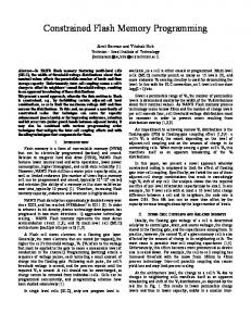
Flash Memory Flash memory has been designed in order to take the place of magnetic storages, e.g. disks. This memory can hold its contents without power supply. Figure 1 shows a structure of NAND type flash memory[TOS92]. The size of a register, which corresponds to a block, is 256 bytes and each page consists of 16 blocks. Write operation consists of following three phase.
1) Erasing: Before rewrite a page (chip), this page (chip) must be cleared by an erasing command. Erasing takes 6-10[ms]. 2) Store: Data are written in data register (Figure l(a)). Compared with access cycle of conventional RAMs, that of flash memory is not so short (currently, 80 lOO[ns]), but access speed is expected to be faster in near future, e.g. IO[ns]. When register is filled, its data are copied to cell array automatically (Figure l(b)).
-
Before rewrite a page (chip) of flash memory, this page (chip) must be cleared by erasing command. The erasing is considered to correspond to the seek operation of disks, but the erasing command changes the status of the databases while disk data are kept during the seek.
3) Self-verification (Figure l(c)): Cell array’s data are verified with register’s data, due t o the lifetime limit of memory cells. The time t o copy and verify is 35[ps].
The maximum number of rewriting operations is limited.
Before read data, cell array’s data are copied to register (Figure l(d)). I t takes 15[fis]. Erasing, store and self-verification are considered to correspond to the seek operation of disks. There is, however, important difference between erasing and seek. When some failure occurs during a seek, any data resided in a disk is not lost since the seek does not change the state of the database, but during the erasing of a page this page is completely lost. In order to take a checkpoint safely, a system is required to have two subsequent checkpoints, and may erase and rewrite the older checkpoint. The system, otherwise, needs t o use some mechanism to protect the data from failure during backup. Although to store two checkpoint data is easy to be realized and usually used, we discuss here, another method where very small buffer memory with battery backup is used in order to store only one checkpoint data in flash memory. Another problem of flash memory is that the maximum number of rewrites for a page is limited, currently one million. A system using flash memory can store whole database as checkpoint data a t 5 minutes interval for 10 years. This may be acceptable for some users, but to store the whole database frequently, e.g. every 5 minutes, is not efficient since many unnecessary pages are also stored in flash memory. Our system
When flash memory is used as the archive storage, these problems should be taken into the consideration. To use disks as the archive storage, many recovery algorithms such as smart reload or frequent reload[GRU91] are proposed. In smart reload frequent access pages are recovered immediately using the archive storage which stores image of main memory. In frequent reload main memory data are stored sequentially in decreasing order of the use frequency on behalf of the recovery. Smart reload takes much time than frequency reload because of many random accesses. Although frequency reload shows the best recovery performance because of the special structure of the archive storage, this algorithm is required heavy computation overhead. In case of flash memory, there is no advantage t o use sequential access, that is, random accesses take the same time as one sequential access to retrieve the same amount of data. The system, therefore, can perform incremental recovery[LEH87] effectively without special structure of archive storage. After discussing basic concepts in Section 2, the organization of continuous backup systems are discussed in Section 3. The performance evaluation of backup systems is discussed in Section 4.
440
pens, the main memory data can be stored to the disk.
16blocks
(a) write
Assumption on failures In this paper, we consider only the case where current main memory data are lost by some failure, e.g power failure, destruction of memory or illegal operations. Multiple failures, e.g. failure of main memory and nonvolatile buffer, is not considered. Destruction of flash memory is not considered.
Continuous Backup Systems
3
(b) store
success
In this section we discuss two methods to realize continuous backup systems. The first one is a system using dual-port DRAMs. Then a twaplane backup system for high-speed DRAMs is discussed.
or
failure
3.1
(c) self-verify
A Continuous Backup System Utilizing Dual-Port DRAMs
Dual-port DRAMs shown in Figure 2 are developed for display memory. The memory contents can be modified through random access port while serial access port is used to display its contents. The data contained in one row are transferred simultaneously to a data register which is connected to the serial access port. As this mechanism is realized by hardware, it is very much efficient. The access cycle of the serial access port is currently 40[ns] and that of the random access port is 2OO[ns]. The basic structure of the system is shown in Figure 2. DM denotes a database manager which consists of a CPU and local memory. BRM denotes a backup and recovery manager which consists of simple logic circuit and flash memory. Checkpoint procedure is performed as follows.
(d) read
Figure 1: Structure of Flash Memory stores pages where at least one update is performed after the latest checkpoint. The waiting time to read the data, not currently in the register, is identical for sequential access or random page access. The access scheduler, therefore, is not required and thus, the overhead of scheduling is eliminated. This contributes to improve the performance of the system and can realize incremental recovery without special structure of the archive storage where each page is stored sequentially according to the access frequency.
[Checkpoint Procedure for a Continuous Backup System Utilizing Dual-Port DRAMs]
Research Overviews on checkpoints for main memory databases Many researchers have discussed to realize efficient backup and recovery algorithm for main memory. A checkpoint algorithm which uses shadow paging technique[DEW84] is discussed in [EIC87]. In order to realize quick recovery of main memory the incremental recovery method is discussed in [LEH87]. In [KUMSl] comparison of incremental recovery with recovery method in [EIC86] is given. In [GRUSl], Eich’s improved recovery algorithms where the incremental recovery is performed are discussed. A method using an uninterruptible power supply (UPS) is discussed in [COP89]. After a failure hap-
0
0
Step 1: BRM accesses the dual-port DRAM through the random access port. The data of one row are transferred from the cell array to the data register (Figure 2(a)). The maximum waiting time of DM for main memory access is the transference time. Step 2: BRM accesses the dual-port DRAM through the serial access port. The register data are transferred to BRM (Figure2(b)). At the same time, DM may access main memory.
BRM executes Steps 1 and 2 until all updated pages are stored in flash memory. One of the problems of
441
Main Bus Am= port
DUI-Port
Figure 3: Structure of High-speed Memory (Synchronous DRAM)
Main Bus
means, therefore, that conventional backup methods where independent two operations, backup operation and database operation, access the same memory port concurrently can not be used. We designed a tweplane backup system in order to solve this problem. The system consists of two memory planes, main memory plane (MMP) and backup memory plane (BMP). Figure 4(a) shows the situation for normal access. During normal access both MMP and BMP are used and they store the identical contents. The checkpoint procedure is performed as follows.
Dual-Port DRAM (b)
Figure 2: Continuous Backup System Utilizing DualPort DRAMs
[Checkpoint Procedure for a Continuous Backup System Utilizing High-speed DRAMs]
this method is that the time-stamps of all pages in BRM are different and compensation operations are required.
3.2
Memory cell array (Bank B)
DRAM
3 readlwrite
Memory cell anay (Bank A)
A Two-Plane Backup System Utilizing High-speed DRAMs
Recently, high-speed DRAMs such as DRAMs based on Rambus, Synchronous DRAMs or Cache DRAMs, have been produced. Figure 3 shows a basic structure of the high-speed DRAMs. Basically, such a DRAM consists of conventional DRAM and a kind of cache which is high-speed SRAM or sense amplifier. The access cycle of current DRAMs based on Rambus is 2[ns] and that of current synchronous DRAMs and cache DRAMs is lO[ns]. In this paper, syqchronous DRAMs are supposed t o be used, but the systems using another high-speed DRAMs become similar architectures. The high-speed DRAMs can realize very short access time by means of their internal caches. Frequent random accesses heavily affect the access speed of DRAMs since they make the hit rate very low. This
0
Step 1: BMP is disconnected from DM and its contents, regarded as checkpoint data, are transferred to BRM until all updated pages are stored in flash memory (Figure 4(b)).
0
Step 2: (In parallel with Step 1) Write operations applied to MMP are stored in Buffer Storage which holds address and written value since MMP is being used during Step 1 (Figure 4(b)).
0
Step 3: After checkpoint data are obtained, Buffer Storage is used to change contents of BMP until BMP catch up with MMP (Figure 4(c)).
After contents of BMP become identical to those of MMP, Buffer Storage is disconnected and the system returns to the configuration shown in Figure 4(a).
3.3
Backup and Recovery Manager
The basic structure of BRM is shown in Figure 5. Address Counter indicates address of main memory and flash memory. Buffer, which consists of small SRAMs with battery, temporarily holds page data
442
Address Counter
I
Main Bus
U
I
1111
Flash Memory
Figure 5: Structure of BRM
L
management. BRM executes following steps during the checkpoint procedure.
J
(b)
[Checkpoint Procedure of BRM] 0 Step 1: BRM reads counter’s value of a page. If it is 0 the page has not been updated since the latest checkpoint and needs not t o be stored in flash memory. If it is not BRM executes Step 2. The purpose of this step is to avoid unnecessary rewrites in order to extend the life time of flash memory and reduce the time required for checkpoint ing.
Main Bus
Buffer Storage
write
0
Figure 4: TwcFPlane Backup System for High-speed DRAMS
transferred from main memory to flash memory while erasing is performed. Access Controller which consists of simple logic circuit controls access to main memory and flash memory, and decides which page of main memory needs to be stored in flash memory. After occurrence of failures BRM recovers main memory database. Since to recover whole database takes long time, BRM executes incremental recovery where frequent accessed (hot) pages are recovered immediately and other pages are recovered on demand. In order to distinguish hot pages from non-hot pages each page has a counter. Each counter consists of few bits, e.g. 2 bits. The counter is incremented at each update to the page and when the counter overflows (when the page is updated three times) it stops counting. The counter’s value is stored in flash memory and resets to 0 at every checkpoint.
Step 2: BRM transfers the main memory page to Buffer.
0
Step 3: BRM erases the flash memory page.
0
Step 4: BRM stores the page into flash memory.
0
Step 5: BRM resets the counter’s value to 0.
Step 1 takes IO[ns] and Step 2 takes 10.24ks1, when a 32bit bus system is used, one page size is 4 kbytes and the access cycle of Buffer and main memory is IO[ns]. In Step 3, to erase a page takes 6[ms]. In Step 4, a page is divided into 16 blocks. BRM transfers 256 byte data to the registers of flash memory (25.6bsI) and flash memory copies register’s data into memory cell by itself (35[ps]). These operations are performed 16 times to store one page. BRM do all Steps in parallel using multi-buffer in order to perform to erase, copy and read counter as background operations of the store operation (Figure 6). The system needs at least 8 buffers each of which consists of 3 flash memories. In our system a erased page cannot be recovered only if both main memory and Buffer fail during checkpoint procedure.
Our system supports ARIES[MOH89] type log 443
Read Store countar (Step 4 )
I
( S t e p 1)
Eraae (Step 3 )
L
Database Account Branch Teller Historv
Record length lOOB lOOB lOOB 50B
Number of recordltps 100000 1 10
Table 1: Definition of Databases Buffer 1 Buffer2 Buffer3
Buffer8
li
Writ.
to be accessed uniformly.
4.2
In this section the time to take checkpoint is discussed. T[s] denotes an interval of subsequent checkpoints. When the page size is 4 kbytes, a page of Account, Branch and Teller has 40 records and that of History has 80 records. The number of Account, Branch, Teller and History pages are as follows.
COPY
i Page j
Block 1
Block 2
Performance of Checkpoint Operations
Block 3
Figure 6: Multi-Buffer From Table 1 all pages of Branch and Teller may to be updated during T, thus all pages of these databases should be stored. All pages of History which are produced during T should be also stored. In case of Account, many pages which are a small part of Account are updated and only these pages should be stored. Since the number of Account page ( N p o g e )is much larger than the number of updates (Nvpdaleand at most tps . T), the access pattern is considered t o obey the Poisson distribution. The probability that a page is updated x times is,
[Recovery Procedure for BRM] At recovery, BRM reads counter's value from flash memory. If the counter overflowed (the page is updated more than three times), this page is regarded as a hot and recovered immediately.
4
Performance Evaluation
In this section performance evaluation on the time to required for checkpoint and recovery from failure is discussed. The evaluation is based on T P C benchmark B[GRA91].
4.1
Here, A =
Outline of TPC Benchmark B
Nim9e - 2zo . The expected value how
NU
date
many pages is updated x times is,
In T P C benchmark B each transaction updates four databases; Account, Branch, Teller and History. Basically, the size of databases, except for History, is in proportion to the number of transactions per second (tps). The profile of a transaction is as follows.
The expected value how many Account's pages are updated is,
Begin transaction. Update a record of Account. Update a record of Teller. Update a record of Branch. Insert a record into History. Commit transact ion.
2=0
Tpogedenotes the time to store a page into flash memory and is supposed to be 40.96[p]. The time to take checkpoint is,
The definition of databases is shown in Table 1. In this paper, every record of each database is supposed
444
p
B a c h Time [SI
10
Recove Time
1
20
30
40 50 60[min] Chekpoint Interval T
Checkpomt Interval T
Figure 7: Checkpoint Interval vs Backup Time
Figure 8: Checkpoint Interval vs Recovery Time
The results from this equation is shown in Figure 7. For example, a 1000 tps system which stores updated pages as checkpoint data at 30-minute interval requires 53.4 seconds to take checkpoint. In case of a 1000 tps system, the size of the whole databases is about 10 Gbytes. The time to store the 10 Gbyte databases is also shown by dotted lines in Figure 7. From Figure 7, when the system stores only updated pages as a checkpoint data at less than 30-minute interval, checkpoint procedure can finish within one minute. In case of a over 1000 tps system, a system is required t o perform checkpoint procedure in parallel in order to reduce the backup time. When the system can take checkpoint in parallel, the backup time may be less than one minute. Our backup systems can easily realize parallel checkpoint procedure since they take checkpoint by simple hardware mechanism.
utilization. When failure occurs just before checkpoint the time to recover becomes maximum,
4.3
Reload Time + Log U t i l i z a t i o n Time
The result from this equation is shown in Figure 8. The minimum recovery time is less than O.Ol[s] when failure occurs just after checkpoint. For example, a 1000 tps system whose checkpoint interval is 30 minutes takes at most 2.3 seconds to recover Branch and Teller. The average time to recover Branch and Teller is N 1.2 seconds. After these databases are recovered the system is restarted. Account and History are recovered concurrently with usual transactions which are discussed in Section 4.1. It takes about 8 minutes to recover Account and History, and during this time the throughput of the system becomes slightly low.
Performance of Recovery Operat ions
In our system the incremental recovery is performed. In T P C benchmark, all pages of Branch and Teller are considered to be hot data and should be recovered immediately. Pages of Account and History are recovered when they are required. During TI at most t p s . T transactions commit. In our log management system, each transaction produces at most four 64 byte log records. In this paper, the time to use log record is considered to be the time to read log record from flash memory, since it takes the most part of time of the log
5
Concluding Remarks
In this paper we have shown a new reliable memory organization utilizing flash memory. We expect the use of flash memory will change traditional file organizations for disks, since file structure suitable for sequential access is not required. Group commit developed for transaction processing systems will not be useful anymore. Software structure for high-speed
445
[KAMSl] Y . Kambayashi, H. Takakura, “Realization of Continuously Backed-up RAMS for HighSpeed Database Recovery,’’ The 2nd International Symposium on DASFAA, 1991.
highly available database is expected to be greatly simplified.
References
[KUMSl] V. Kumar, A. Burger, “Performace Measurement of Some Main Memory Database Recovery Algorithms,” Proc. 7th Int. Conf. Data Engineering, 1991, pp.436-443.
[BER87] P.A. Bernstein, V. Hadzilacos, N. Goodman, “Concurrency Control and Recovery in Database Systems,” Addison Wesley, 1987.
[LEH87] T.J. Lehman, M.J. Carey “A Recovery Algorithm for A High-Performance MemoryResident Database System,’’ Proc. ACM SIGMOD Conf., 1987, pp104-117.
[COP891 G .Copeland, T.Keller , R.Krishnamurthy, M.Smith, ‘The Case For Safe RAM,” Proc. of the 15th International Conf. on VLDB, 1989, pp.327-335.
[LEH89] T.J. Lehman, M.J. Carey “A Concurrency Control Algorithm for Memory-Resident Database Systems,” Proc. 3rd International Conf, FODO, 1989, pp.490-504.
[DEW841 D. DeWitt, et al, “Implementation Techniques for Main Memory Database Systems,” Proc. of ACM SIGMOD Conf., 1984, pp.1-8. [EIC86]
M.H. Eich, “Main Memory Database Recovery,” ACM FJCC, 1986, pp.12261232.
[E1C 871
M.H. Eich, “A classification and Comparison of Main Memory Database Recovery Techniques,” Proc. IEEE 3rd Conf. on Data Engineering, 1987, pp. 332-339.
[EIC88]
M.H. Eich, “MARS : The Design of a Main Memory Database Machine,” Database Machines and Knowledge Base Machines, Kluwer Academic Publishers, 1988, pp.325338.
[EIC89]
M.H. Eich, “Main Memory Database Research Directions,” Proc. 6th International Workshop , IWDM‘89, 1989, pp.25 1-268.
[MOH891 C. Mohan, D. Haderle, B. Lindsay, H. Piahesh, P. Schwarz, “ARIES: A Transaction Recovery Method Supporting FineGranularity Locking and Partial Rollbacks Using Write-Ahead Logging,” IBM Research Report FLJ6649, IBM Almaden Research Center, January 1989; Revised April 1991. [MOH901 C. Mohan, K. Treiber, R. Obermarck, “Algorithms for the Management Remote Backup Data Base for Disaster Recovery,” IBM Research Report RJ7885R, IBM Almaden Research Center, December 1990; Revised June 1991. [TAK92] H. Takakura, Y. Kambayashi, “A Transparent Back-up System for a Main Memory Database and Its Performance Evaluation,” 44th National Convention Record of IPSJ, 4-181, March, 1992 (in Japanese).
Hot Spots’ in [GAW85] D. Gawlick, “Processing High Performance Systems,” Proc. of IEEE Spring Computer Conference, 1985, pp.249251.
[TOS92] Toshiba, NAND E’PROM, FT-TC584000P /F/Ft/FR, Data Sheet, June, 1992.
[GRASl] Jim Gray, “The Benchmark Handbook,” Morgan Kaufmann Publishers, 1991, pp.19117.
[GRU9 11 L. Gruenwalld, M.H. Eich, “MMDB Reload Algorithms,” Proc. of ACM SIGMOD International Conf. on Management of Data, 1991, pp.397-405. [HAG861 R.B.Hagmann, “A Crash Recovery Scheme for a Memory-Resident Database System,” IEEE Trans. on Computers, Vol. C-35, No.9, September, 1986, pp.839-843.
446