Apr 12, 1995 - library information systems, entertainment industry, scienti c ... supported in part by the National Science Foundation under grants IRI-9222926, ...
Continuous Display of Video Objects Using Multi-Zone Disks
�
Shahram Ghandeharizadeh, Seon Ho Kim, and Cyrus Shahabi Department of Computer Science University of Southern California Los Angeles, California 90089 April 12, 1995 Abstract
Video servers are expected to play an important role in a number of application domains, e.g., library information systems, entertainment industry, scienti c applications, etc. A challenging task when implementing these systems is to ensure a continuous display of audio and video objects. If special precautions are not taken, the display of an object may su�er from frequent disruptions and delays, termed hiccups. A second challenging task is to con gure a system to meet the performance requirements of an application: its desired number of simultaneous displays and the waiting tolerance of a display. For applications with large data sets, e.g., video servers, magnetic disks have established themselves as mass storage device of choice. A technique to increase the storage capacity of disks is zoning. A side-e�ect of zoning is that it introduces a disk drive with variable transfer rates. This paper describes techniques to support a continuous display of video objects using a multi-zone disk drive. As compared to previous approaches, the proposed techniques harness the average transfer rate of the magnetic disk (instead of its minimum transfer rate). In addition, we describe a con guration planner that logically manipulates the zoning information of a disk drive to support the performance criteria of an application.
� This research was supported in part by the National Science Foundation under grants IRI-9222926, IRI-9110522, IRI9258362 (NYI award), and CDA-9216321, and a Hewlett-Packard unrestricted cash/equipment gift.
1 Introduction A technological trend in the area of magnetic disks is an increase in their storage capacity (a 25% increase a year). Zoning is one approach to accomplish this. A side e�ect of zoning is that it introduces a disk drive with variable transfer rates: the di�erent regions of a disk drive, termed zones, provide di�erent transfer rates. For example, a Seagate ST31200W disk consists of 23 zones with bandwidths varying from 2.33 to 4.17 megabytes per second (MB/s), see Table 1b. A number of studies have investigated techniques to support a hiccup-free display of continuous media, video and audio, using magnetic disk drives [AH91, RVR92, RV93, VR93, CL93, TPBG93, RW94a, YCK93, Gem93]. These studies assume a xed transfer rate for a disk drive. If a system designer elects to use one of these techniques, the system is forced to use the minimum transfer rate of the zones for the entire disk in order to guarantee a continuous display of video objects. We term these studies collectively as minimum transfer rate zone designs, Min-Z-tfr. (Section 3.3 describes a cycle-based technique [TPBG93, BGM95] that falls into Min-Z-tfr category.) This study introduces two alternative techniques, VARB and FIXB, that harness the average transfer rate of zones while ensuring a continuous display. Assuming the bandwidth required to display an object is 1.5 Mb/s, our proposed techniques enable a Seagate 31200W disk to support 17 simultaneous displays as compared to 12 with Min-Z-tfr. While 17 versus 12 may appear insigni cant at rst glance, this is a ?12 ) that has a signi cant impact on the performance of scalable multi-disk servers. 40% improvement ( 1712 For example, with a 1000 disk system, the proposed techniques harness enough of the disk bandwidth to support 17,000 simultaneous displays as compared to 12,000 with Min-Z-tfr. (See [GK95] for factors that impact the scalability characteristics of parallel servers.) However, both FIXB and VARB su�er from two limitations when restricted to employ the physical zone con guration provided by the vendor: First, they result in a higher latency, i.e., the time elapsed from when the request arrives until the onset of its display. Second, they waste disk space. We eliminate these limitations using a con guration planner that consumes the performance requirements of an application, and manipulates the zoning information to support the performance criteria of an application. The experimental results indicate that the output of the planner almost always provides signi cant savings as compared to Min-Z-tfr. Min-Z-tfr cannot outperform our planner because it is simulated as one of the possible con gurations. There are three factors that are manipulated by the con guration planner: the percentage of wasted disk space, the number of simultaneous displays (i.e., throughput) supported by the disk, and the maximum latency incurred by a display. Trading latency time for a higher throughput is dependent on the requirements of the target application. One may increase the throughput of the Seagate from 10 to 17 displays using the physical zone characteristics (with VARB). This causes the maximum latency to increase from 9.2 seconds to 3.2 minutes (see the seventh column of Table 4). A small local video-on-demand server may expect to have 1
17 simultaneous displays as its maximum load with each display lasting two hours. With Min-Z-tfr, the disk drive supports a maximum of 12 simultaneous displays, each observing a 7.8 seconds latency. During peak system loads (say 17 active requests), several requests may wait in a queue until one of the active requests completes its display. These requests observe a latency time signi cantly longer than a second (potentially in the range of hours depending on the status of the active displays and the queue of pending requests). In this scenario, it might be reasonable to force each request to observe a worst case latency of 3.2 minutes in order to support 17 simultaneous displays. Alternatively, with a news on demand application whose typical video clips have a display time of approximately four minutes, a 3.2 minute latency time might not be a reasonable tradeo� for a higher number of simultaneous displays. In this case, the planner might choose an alternative zone con guration that supports a lower latency time by reducing system throughput. To illustrate the impact of wasted disk space, assume a hierarchical multimediastorage manager consisting of memory, magnetic disk, and a tertiary storage device. As compared with the magnetic disk, the tertiary storage device provides a low storage cost (desirable). However, a request observes a higher latency and a lower transfer rate (undesirable) when retrieving data from this device. The data resides permanently on the tertiary storage device. The working set of an application is rendered disk resident to minimize the number of references to the tertiary storage device. The working set [Den68] of an application consists of a collection of objects that are repeatedly referenced during a xed interval of time. For example, in existing video stores, a few titles are expected to be accessed frequently and a store maintains several (sometimes many) copies of these titles to satisfy the expected demand. These titles constitute the working set of a video-on-demand server. If the amount of wasted disk space is such that the working set of an application can become disk resident then the impact of wasted space is marginal. Otherwise, the amount of wasted space may reduce system performance due to frequent references to the tertiary storage device (that has a lower performance when compared to the magnetic disk drive). We quantify this factor and consider its impact in our experimental studies. Given a disk, the proposed planner logically manipulates zones to satisfy the performance objectives of an application (i.e., expected number of active customers as well as their waiting tolerance) based on the size of its working set. The rest of this paper is organized as follows. Section 2 provides an overview of a magnetic disk drive and the concept of zoning. Section 3 describes two alternative techniques (FIXB and VARB) that ensure a hiccup-free display of video objects using a multi-zone disk drive. In addition, it quanti es the tradeo�s associated with these two techniques and compares them with a cycle-based approach. Section 4 describes the con guration planner and its heuristic based search mechanism. Section 5 evaluates the proposed techniques using Min-Z-tfr as the comparison point. The results demonstrate the superiority 2
Spindle Arm Arm assembly
Head Platter
Cylinder
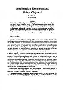
Figure 1: A disk drive of our proposed techniques. Our conclusions and future research directions are contained in Section 6.
2 Overview of a Magnetic Disk Drive A magnetic disk drive is a mechanical device, operated by its controlling electronics. The mechanical parts of the device consist of a stack of platters that rotate in unison on a central spindle (see [RW94b] for details). Presently, a single disk contains one, two, or as many as sixteen platters (see Figure 1). Each platter surface has an associated disk head responsible for reading and writing data. Each platter is set up to store data in a series of tracks. A single stack of tracks at a common distance from the spindle is termed a cylinder. To access the data stored in a track, the disk head must be positioned over it. The operation to reposition the head from the current track to the desired track is termed seek. Next, the disk must wait for the desired data to rotate under the head. This time is termed rotational latency. To meet the demands for a higher storage capacity, disk drive manufacturers have introduced disks with zones. A zone is a contiguous collection of disk cylinders whose tracks have the same storage capacity. Tracks are longer towards the outer portions of a disk platter as compared to the inner portions, hence, more data may be recorded in the outer tracks. While zoning increases the storage capacity of the disk, it produces a disk that does not have a single transfer rate. The multiple transfer rates are due to (1) the variable storage capacity of the tracks and (2) a xed number of revolutions per second for the platters. Table 1 presents the zone characteristics of two commercial disk drives. Both are SCSI-2 fast and wide disks with a 1 gigabyte storage capacity. A disk performs useful work when transfering data and wasteful work when performing seek operation. The seek time is a function of the distance traveled by the disk arm [BG88, GHW90, RW94b]. Several studies have introduced analytical models to estimate seek time as a function of this distance. Other studies have investigated techniques to minimize the seek time [GKS95, BMC94, YCK93]. One approach is based on Constrained Allocation. It controls the placement of blocks of di�erent objects on the disk surface to 3
Zone # 0 1 2 3 4 5 6 7
Zone # Size (MB) Transfer Rate (MB/s) 0 140.0 4.17 1 67.0 4.08 2 45.0 4.02 3 46.0 3.97 4 44.0 3.88 5 42.0 3.83 6 41.0 3.74 7 56.0 3.60 8 39.0 3.60 9 37.0 3.50 10 52.0 3.36 11 35.0 3.31 12 34.0 3.22 13 46.0 3.13 14 32.0 3.07 15 31.0 2.99 16 42.0 2.85 17 28.0 2.76 18 27.0 2.76 19 37.0 2.62 20 25.0 2.53 21 34.0 2.43 22 20.0 2.33
Size (MB) Transfer Rate (MB/s) 324.0 3.40 112.0 3.17 76.0 3.04 77.0 2.92 71.0 2.78 145.0 2.54 109.0 2.27 89.0 2.02
(a) Hewlett-Packard C2247 disk
(b) Seagate ST31200W disk
Table 1: Two commercial disks and their zoning information minimize the distance traveled by the disk arm. Our proposed techniques employ this approach to localize block references to a single zone. Hence, when multiplexing the disk bandwidth among retrieval of N blocks, the incurred seek time is bounded by the maximum seek time within a zone. Let Seek(k) denote the time required for the disk arm to travel k cylinders to reposition itself from cylinder i to cylinder i + k (or i ? k). Hence, Seek(1) and Seek(#cyl) denote the time required to reposition the disk arm between two adjacent cylinders, and the rst and the last cylinder of a disk (with #cyl cylinders), respectively. Consequently, for a disk drive with m zones the average time required to move among the cylinders within a zone is Seek( #mcyl ). (Note that Seek( #mcyl ) 6= Seekm(#cyl) .) This model becomes more complex because our planner (Section 4) logically combines two physically adjacent zones and treat them as a single zone. The worst seek time of this zone is now di�erent because m is reduced. We eliminate this factor from discussion by using a constant worst seek time for each zone. We made this simplifying assumption in order to focus on variable transfer rate of a magnetic disk drive that deserves special attention (instead of seek time that has been investigated by the previous studies). The extensions of this study to incorporate the variable worst seek time for the reads localized to a zone is straightforward.
3 Continuous Display This section presents two alternative designs to support a continuous display of video objects. We assume 4
Term
De nition Worst seek time of a zone (including the maximum rotational latency time) Tcseek Seek time required to make a complete span cap Total capacity of a disk drive m Number of zones in a disk drive Zi Zone i of a disk drive, where 0 � i < m R(Zi ) Transfer rate of Zi , in MB/s size(Zi ) Capacity of Zi B(Zi ) Block size of Zi with VARB B Fixed block size with FIXB Gi Group i, constructed from merging two or more zones R(Gi ) Transfer rate of Gi , in MB/s size(Gi ) Capacity of Gi Tscan Time to perform one sweep of m zones TMUX (Zi ) Time to read N blocks from zone Zi size(WS ) Size of the application working set RC Display bandwidth requirement (Consumption rate), in MB/s Mem Required amount of memory N Maximum number of simultaneous displays (throughput) ` Maximum latency time C Total system cost
TW
Seek
Table 2: List of terms used repeatedly in this paper and their respective de nitions the following: 1. a disk with m zones: Z0 , Z1, ..., Zm?1 . The transfer rate of a zone i is denoted as R(Zi ). Z0 denotes the outermost zone with the highest transfer rate: R(Z0 ) � R(Z1 ) � ::: � R(Zm?1 ). 2. a single media type with a xed display bandwidth, RC . 3. the display bandwidth is less than or equal to the average transfer rate of the disk, RC �
Pm?1 R(Zi) i=0
m
.
The two proposed techniques partition each object X into f blocks: X0 , X1 , X2 , ..., Xf ?1 . The rst, termed FIXB, renders the blocks equi-sized. With the second technique, termed VARB, the size of a block depends on the transfer rate of its assigned zone. The advantage of FIXB is its ease of implementation. There are two reasons for this claim. First, a xed block size simpli es the implementation of a le system that serves as the interface between memory and magnetic disk drive. Second, the design and implementation of a memory manager with xed frames (the size of a frame corresponds to the size of a block) is simpler than one with variable sized frames. This is particularly true in the presence of multiple displays that give rise to race conditions when competing for the available memory1. While VARB might be more complicated to implement, it requires a lower amount of memory and incurs a lower latency as compared to FIXB when the bandwidth We have participated in the design, coding, and debugging of a multi-user bu�er pool manager with a xed block size for a relational storage manager. We explored the possibility of extending this bu�er pool manager to support variable block size, and concluded that it required signi cant modi cations. 1
5
Time
TScan T MUX
TMUX
Z0
Z1
Zone ID
Disk Activity
0
TW_Seek
1
...
N-1
0
1
Tcseek
...
TMUX Z m-1
...
N-1
...
0
1
...
N-1
Tdisk(Z 1)
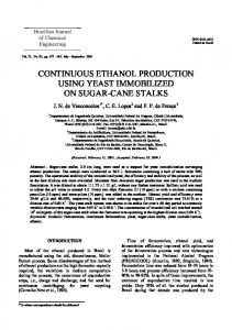
Figure 2: TScan and its relationship to TMUX of the disk drive is exhausted. FIXB and VARB share many common characteristics. In Section 3.1, we describe FIXB. Subsequently, Section 3.2 describes VARB and its di�erences as compared to FIXB. Section 3.3 compares these two techniques with a cycle-based [TPBG93, BGM95] approach. Section 3.4 quanti es the tradeo�s between VARB and FIXB.
3.1 Fixed Block Size, FIXB With this technique, the blocks of an object X are rendered equi-sized. Let B denote the size of a block. The system assigns the blocks of X to the zones in a round-robin manner starting with an arbitrary zone. FIXB con gures the system to support a xed number of simultaneous displays, N . This is achieved by requiring the system to scan the disk in one direction, say starting with the outermost zone moving inward, visiting one zone at a time and multiplexing the bandwidth of that zone among N block reads. Once the disk arm reads N blocks from the innermost zone, it is repositioned to the outermost zone to start another sweep of the zones. The time to perform one such a sweep is denoted as TScan . The system is con gured to produce and display an identical amount of data per TScan period. The time required to read N blocks from zone i, denoted TMUX (Zi ), is dependent on the transfer rate of zone i. This is because the time to read a block (Tdisk (Zi )) during one TMUX (Zi ) is a function of the transfer rate of a zone. Figure 2 shows TScan and its relationship with TMUX (Zi ) for m zones. During each TMUX period, N active displays might be referencing di�erent objects. This would force the disk to incur a seek when switching from the reading of one block to another, termed TW Seek . TW Seek also includes the maximum rotational latency time. At the end of a TScan period, the system observes a long seek time (Tcseek ) attributed to the disk repositioning its arm to the outermost zone. The disk produces m blocks of X during one TScan 6
MEM Max Required Memory
R C *(TMUX (Zi)-Tdisk (Z i)) (R (Z i) - R C )*Tdisk(Z i )
...
...
Tdisk (Zi )
TIME (Sec)
0 TMUX (Z0 ) TMUX (Z1)
...
...
TMUX (Z i)
TMUX (Zm-2 )
TMUX(Zm-1 )
Tcseek
TScan
Figure 3: Memory required on behalf of a display period (m � B bytes). The number of bytes required to guarantee a hiccup-free display of X during TScan should either be lower than or equal to the number of bytes produced by the disk. This constraint is formally stated as:
RC � (Tcseek +
mX ?1 i=0
TMUX (Zi )) � m � B
(1)
The amount of memory required to support a display is minimized when the left hand side of Equation 1 equals its right hand side. During a TMUX , N blocks are retrieved from a single zone, ZActive. In the next TMUX period, the system references the next zone Z(Active+1) mod m . When a display references object X, the system computes the zone containing X0 , say Zi . The transfer of data on behalf of X does not start until the active zone reaches Zi . One block of X is transfered into memory per TMUX . Thus, the retrieval of X requires f such periods. P ?1 T (Z (The display of X may exceed fj =0 MUX (i+j ) mod m ) periods as described below.) The display of object X requires some memory due to the variable transfer rate. This is best illustrated using an example. Assume that the blocks of X are assigned to the zones starting with the outermost zone, Z0 . If ZActive is Z0 then this request employs one of the idle Tdisk (Z0 ) slots to read X0 . Moreover, its display can start immediately because the outermost zone has the highest transfer rate. The block size and N are chosen such that the data accumulates in memory when accessing outer zones and decreases when reading data from inner zones on behalf of a display (see Figure 3). In essence, the system uses bu�ers to compensate for the low transfer rates of inner zones using the high transfer rates of outer zones, harnessing the average transfer rate of the 7
disk. Note that the amount of required memory reduces to zero at the end of one Tscan in preparation for another sweep of the zones. The display of an object may not start upon the retrieval of its block from the disk drive. This is because the assignment of the rst block of an object may start with an arbitrary zone while the transfer and display of data is synchronized relative to the outermost zone, Z0 . In particular, if the assignment of X0 starts with a zone other than the outermost zone (say Zi , i 6= 0) then its display must be delayed to avoid hiccups. The duration of this delay depends on: 1) the time elapsed from retrieval of X0 to the time that block Xm?i is retrieved from zone Z0 , termed TaccessZ0 , and 2) the amount of data retrieved during TaccessZ0 . If the display time of data corresponding to item 2 (Tdisplay(m?i) ) is lower than TaccessZ0 , then the display must be delayed by TaccessZ0 ? Tdisplay(m?i) . To illustrate, assume that X0 is assigned to the innermost zone Zm?1 (i.e., i = m ? 1) and the display time of each of its block is 4.5 seconds, i.e., Tdisplay(1) = 4:5 seconds. If 10 seconds elapse from the time X0 is read until X1 is read from Z0 then the display of X must be delayed by 5.5 seconds relative to its retrieval from Zm?1 . Otherwise, its display may su�er from a 5.5 second hiccup if initiated upon retrieval. The delay to avoid hiccup is shorter than the duration of a Tscan. Indeed, the maximum latency observed by a request is Tscan when the number of active displays is less than2 N : ` = TScan = Tcseek +
mX ?1 i=0
TMUX (Zi )
(2)
This is because at most N ? 1 displays might be active when a new request arrives referencing object X. In the worst case scenario, these requests might be retrieving data from the zone that contains X0 (say Zi ) and the new request arrives too late to employ the available idle slot. (Note that the display may not employ the idle slot in the next TMUX because Zi+1 is now active and it contains X1 instead of X0 .) Thus, the display of X must wait one Tscan period until Zi becomes active again. One can solve for the block size by observing from Figure 2 that TMUX (Zi ) can be de ned as:
B +T TMUX (Zi ) = N � ( R(Z W Seek ) i)
(3)
Substituting this into Equation 1, the block size is de ned as: � TW Seek) B = RC � (Tcseek + mP�mN (4) m ? RC � i=0?1 R(NZi) Observe that FIXB wastes disk space when the storage capacity of the zones is di�erent. This is because once the storage capacity of the smallest zone is exhausted then no additional objects can be stored as they would violate a round-robin assignment3. Section 3.4 quanti es the percentage of disk bandwidth wasted by FIXB for the commercial disks of Table 1. When the number of active displays exceeds N then this discussion must be extended with appropriate queuing models. Unless the number of blocks for an object is less than m. We ignored this case from consideration because video objects are typically very large. 2
3
8
3.2 Variable Block Size, VARB VARB is similar to FIXB except that it renders the duration of TMUX (Zi ) identical for all zones. This is achieved by introducing variable block size where the size of a block, B(Zi ), is a function of the transfer rate of a zone. This causes the transfer time of each block, Tdisk to be identical for all zones (i.e., Tdisk = RB((ZZii)) = RB((ZZjj)) for 0 � (i; j) < m). Similar to FIXB, the blocks of an object are assigned to the zones in a round-robin manner and the concept of TScan is preserved. This means that the blocks of an object X are no longer equi-sized. The size of a block X depends on the zone it is assigned to. However, the change in block size requires a slight modi cation to the constraint that ensures a continuous display:
RC � (Tcseek + m � TMUX ) �
mX ?1 i=0
B(Zi )
(5)
The duration of TMUX is now independent of the transfer rate of a zone and is de ned as: TMUX = N � (Tdisk + TW Seek )
(6)
Substituting this into Equation 5, the size of a block for a zone Zi is de ned as:
� N � m + RC � Tcseek B(Zi ) = R(Zi ) � RC �PTmW?Seek 1 R(Z ) ? R � N � m i C i=0
(7)
Similar to FIXB, VARB employs memory to compensate for the low bandwidth of inner zones using the high bandwidth of the outer zones. This is achieved by reading more data from the outer zones. Moreover, the display of an object X is synchronized relative to the retrieval of its block from the outermost zone and (Zi) size(Zj ) may not start immediately upon retrieval of X0 . VARB wastes disk space when size R(Zi) 6= R(Zj ) for i 6= j, and 0 � (i; j) < m. The amount of wasted space depends on the zone that accommodates the fewest blocks. This is because the blocks of an object are assigned to the zones in a round-robin manner and once the capacity of this zone is exhausted the storage capacity of other zones cannot be used by other video objects.
3.3 A Comparison with Cycle-based Approach A general approach to support continuous displays of N simultaneous video objects is a cyclic approach. This approach stripes each object into a number of blocks. Subsequently, the disk bandwidth is multiplexed among retrieval of N blocks corresponding to N di�erent objects, within a cycle. There are two variations of this approach: cycle-based [TPBG93, BGM95] and pipelining [GR93, BGMJ94]. With cycle-based, the blocks retrieved in one cycle are displayed in the next cycle. With pipelining, the display of each block starts as soon as its retrieval is initiated. Hiccups are eliminated by prefetching and choosing appropriate block sizes (as described in Section 3.1 and 3.2). The major advantage of cycle-based is that the order of block retrieval can be shu�ed within a cycle [YCK93] to force the movement of the disk arm to simulate 9
N 1 2 4 8 10 12 13 14 15 16 17
FIXB VARB Block Size Minimum Block Maximum Block Average Block (MBytes) Size (MBytes) Size (MBytes) Size (MBytes) 0.0040 0.0028 0.0050 0.0040 0.0083 0.0058 0.0104 0.0082 0.0188 0.0132 0.0235 0.0187 0.0539 0.0370 0.0663 0.0525 0.0863 0.0584 0.1044 0.0828 0.1442 0.0949 0.1698 0.1345 0.1945 0.1249 0.2236 0.1772 0.2773 0.1717 0.3072 0.2434 0.4396 0.2540 0.4546 0.3602 0.9014 0.4378 0.7835 0.6208 12.4333 1.2117 2.1685 1.7183
Table 3: Seagate ST31200W disk the scan algorithm [Teo72], minimizing the disk seek time. A limitation of this approach is its high memory requirement attributed to its double bu�ering characteristic (twice as much as that of pipelining). Both FIXB and VARB employ pipelining for the following two reasons. First, the transfer rate of a multi-zone disk drive is not xed, resulting in a variable duration of a cycle. This complicates the memory management within a cycle. Second, our techniques control the placements of the blocks across the disk surface such that any two blocks retrieved within a cycle reside on a single zone. Hence, the incurred seek time between retrieving two blocks is much less than the maximum seek time of the disk (see Section 2). This renders the bene ts of a shu�ing blocks in a cycle marginal.
3.4 FIXB vs VARB While VARB determines the block size based on transfer rate of the individual zones, FIXB determines the block size as a function of the average transfer rate of the zones. In essence, VARB performs local optimization while FIXB performs global optimization. This enables VARB to choose smaller block sizes when compared to FIXB for a xed number of users. Table 3 presents the required block size as a function of the number of simultaneous displays (N ) for the Seagate disk drive4 . The bandwidth requirement of objects that constitute the database is 1.5 Mb/s (RC =1.5 Mb/s). The average transfer rate of the disk can support a maximum of 17 simultaneous displays. A small block size minimizes the duration of TScan which, in turn, reduces the amount of required memory. This is re ected by the results presented in Table 4. For each of VARB and FIXB, this table presents the required memory, latency5 , percentage of wasted disk space and bandwidth as a function of N . For 17 users, the memory requirement of a system with FIXB is seven times higher than that with VARB. Moreover, the maximum incurred latency is more than 20 minutes with FIXB as compared to 3.25 minutes 4 5
The numbers for the HP disk drive are contained in Appendix A. Latency is equivalent to the duration of TScan.
10
N 1 2 4 8 10 12 13 14 15 16 17
FIXB VARB Memory Latency % wasted % Avg wasted Memory Latency % wasted % Avg wasted MBytes (Sec) disk space disk bandwidth MBytes (Sec) disk space disk bandwidth 0.0071 0.4440 58.0014 94.1464 0.0116 0.4431 40.4412 94.3256 0.0234 0.9253 58.0131 88.2928 0.0444 0.9216 40.4538 88.6511 0.1074 2.1088 58.0094 76.5855 0.1926 2.0892 40.4577 77.3022 0.7458 6.0390 58.1044 53.1710 1.0597 5.8805 40.4602 54.6044 1.6425 9.6687 58.1225 41.4638 2.0780 9.2682 40.5678 43.2555 3.6018 16.1544 58.2005 29.7566 4.0407 15.0658 40.6783 31.9067 5.4888 21.7797 58.3462 23.9029 5.7592 19.8459 40.4624 26.2322 8.7803 31.0538 58.0774 18.0493 8.5119 27.2647 40.6993 20.5577 15.5152 49.2304 58.4618 12.1957 13.4815 40.3406 41.0019 14.8833 35.2593 100.9605 58.3538 6.3421 24.7663 69.5311 41.3331 9.2088 536.1229 1392.5277 73.8901 0.4885 72.7829 192.4524 42.2643 3.5344
Table 4: Seagate ST31200W disk with VARB. The percentage of wasted disk space with each of FIXB and VARB is dependent on the physical characteristics of the zones. While VARB wastes a lower percentage of the Seagate disk space, it wastes a higher percentage of the HP disk space (see Table 11 in Appendix A). The average percentage of wasted disk bandwidth is lower with FIXB because it minimizes this value from a global perspective. With VARB, a number of outer zones waste a higher percentage of their bandwidth in favor of a smaller block size (these zones increase the percentage of wasted disk bandwidth).
4 Con guration Planner Alternative applications have di�erent performance objectives. It may not always be desirable to incur a high latency to support a large number of displays. For examples, an application might desire fewer displays in favor of a lower latency time. Hence, it might be bene cial to combine some zones (reduce m) to reduce the latency time. This would reduce the average transfer rate of the disk that might minimize the number of simultaneous displays supported by the system. Another application with a very small working set might require a high throughput and a low latency time. If the working set of this application ts in the outermost zone of the disk then the system should eliminate all the other zones, harnessing the highest transfer rate for this application. By eliminating m ? 1 zones, the incurred latency is also minimized. These examples motivate the need for a con guration planner that logically manipulates the zoning characteristics of a disk to satisfy the performance objectives of a target application. The inputs to the planner include the characteristics of an application, its performance objectives, and the physical attributes of the target disk drive. The characteristics of an application include RC and the size of its working set. The performance objectives of the application include its desired latency (`desired ) 11
Q = < N, l, B, C > DZA1
ODZA
REDUCE Heuristics (e.g., MaxT)
Reduced DZA
Exhaustive Iteration
DZA2 . . .
Q1 Q2
Core
. . .
a. Class of REDUCE heuristics
Q = < N, l, B, C > DZA1 DZA2 . . .
BYPASS ODZA
Heuristics (e.g., MinW)
Q1 Q2
Core
. . .
b. Class of BYPASS heuristics
Figure 4: Two alternative classes of heuristics and throughput (Ndesired ). The physical attributes of a disk include: TW Seek , Tcseek , and its Disk Zone Arrangement (DZA). The outputs of the planner are a new DZA and an appropriate block size that satis es the performance objectives while minimizing cost. A new DZA can be constructed by: 1) merging one or more adjacent zones into one, termed merge, 2) eliminating one or more zones from consideration, termed eliminate, 3) splitting a zone into several zones, termed split, and 4) a combination of the rst three techniques. The planner consists of three components. The rst component constructs all possible DZAs using a combination of merge and eliminate. A second component, termed core, computes the possible throughput, latency, memory requirement, and costs of using a DZA with either FIXB or VARB. It employs the analytical models of Section 3 for this computation. One can employ these two components to nd the cheapest con guration that supports the performance objectives of an application (i.e., `desired and Ndesired ). However, as described later in Section 4.2, the number of possible DZAs becomes large when a disk consists of a large number of zones, requiring years of computation to complete this exhaustive search. As a solution, the third component of the planner introduces heuristics. Two classes of heuristics are described: 1) REDUCE: these heuristics construct a new DZA, termed Reduced DZA, that consists of fewer zones than the original DZA, that is used as input to the rst component of the planner (see Figure 4a), 2) BYPASS: these heuristics eliminate the rst component of the planner all together by producing a select number of DZAs based on the knowledge of target application (see Figure 4b). In the following, we describe each of these components starting with the core.
4.1 The Core The input parameters of core are similar to those of the planner (see Figure 5). Core employs the analytical models of Section 3 to output possible values of N , `, B, and C (for either FIXB or VARB). It iterates over possible values of N to generate these quadruples. The lower and upper bound for N are Ndesired 12
and b RR(ZC0 ) c, respectively. C denotes the cost of the system. It is computed as a function of the amount of memory (Mem) required by the target application:
C = (Mem � $ram) + $disk
(8)
where $ram is the cost of memory per megabyte, and $disk is the cost of the single disk drive required by the application. The amount of wasted disk space (W) is used for two purposes. First, it is used to eliminate those DZAs that avoid the working set of an application from becoming disk resident; size(WS) � cap ? W, where size(WS) and cap denote the size of the working set and the disk storage capacity, respectively. Second, the waste is used to compute the extra latency time observed by requests referencing objects that do not constitute the working set of the target application. The larger the waste, the higher the probability that a reference to a non-working set object is directed to the tertiary storage device, resulting in a higher average latency time. To compute the extra latency, we use the average size of an object (SizeAvg req ) to size(DB) c) and the working estimate the number of objects that constitute the database (#(DB) = b Size Avg req size(WS ) c). Thus, the number of objects that do not constitute the working set is set (#(WS) = b Size Avg req #(DB) ? #(WS). A DZA may enable a larger number of objects than #(WS) to become disk resident, termed #(DZA). #(DZA) must be greater than or equal to #(WS). Otherwise, it would have been eliminated. Let #(REM) denote #(DZA) ? #(WS). Let p1 be the probability that a request references objects inside the working set. Assuming that references are randomly distributed across the objects that constitute the portion of the database excluding its working set, the probability that a reference to one such object is #(REM ) . Thus, the probability that a request retrieves data from the directed to tertiary is pter = 1 ? #(DB )?#(WS ) Avg req tertiary is (1 ? p1) � pter . It will observe a minimum extra latency time of Size DTertiary , where DTertiary is the transfer rate of the tertiary storage device. Multiplying these components with one another, the extra latency time observed due to the wasted space is computed as: #(REM) ) � SizeAvg req (1 ? p1 ) � (1 ? #(DB) ? #(WS) D Tertiary
(9)
Core's output is a number of quadruples Q =< N ; `; B; C >, where C is the cost (computed using Eq. 8), and B either denotes block size with FIXB or the largest block size (corresponding to the outermost zone) with VARB6 . Note that the latency time (`) incorporates both latency times computed in Eqs. 2 and 9. One can invoke Core using alternative input DZAs to generate a list of quadruples. Subsequently, a search procedure can traverse the list to locate a quadruple Q =< N ; `; B; C >, that is both the cheapest in the list (i.e., has the minimum C value), and satis es the following conditions: Ndesired � N and `desired � `. 6
The block size for any zone Zi can then be computed as B(Zi ) = R BZ0 � R(Zi ). (
13
)
ldesired Ndesired
Tcseek , TW_Seek
Size of the application WS
Core
RC
< N, l, B, C >
Disk-Zone-Arrangement: m, (R(Zi), size(Zi)) 0