CORONA: A Coordinate and Routing system for Nanonetworks Ageliki Tsioliaridou
Christos Liaskos
FORTH - Greece
FORTH - Greece
{atsiolia}@ics.forth.gr
{cliaskos}@ics.forth.gr Andreas Pitsillides
Sotiris Ioannidis FORTH - Greece
{sotiris}@ics.forth.gr
University of Cyprus
[email protected] ABSTRACT The present paper introduces a joint coordinate and routing system (CORONA) which can be deployed dynamically on a 2D ad-hoc nanonetwork. User-selected nodes are used as anchor-points at the setup phase. All nodes then measure their distances, in number of hops, from these anchors, obtaining a sense of geolocation. At operation phase, the routing employs the appropriate subset of anchors, selected by the sender of a packet. CORONA requires minimal setup overhead and simple integer-based calculations only, imposing limited requirements for trustworthy operation. Once deployed, it operates efficiently, yielding a very low packet retransmission and packet loss rate, promoting energy-efficiency and medium multiplexity.
Keywords Wireless Networking, Nanoscale.
1.
INTRODUCTION
Advances in nanotechnology enable the development of tiny machines from nanoscale components, namely nanomachines. Composed of a power supply, a memory, an antenna and a CPU module, nanomachines are entirely autonomous nodes which are able to perform simple operations and communicate in short distances. Currently, miniature graphene based antennas [1] are introduced giving nanomachines the ability to achieve high transmission rates over very short distances when operating in the most promising operating spectrum of Terahertz Band [5],[2]. Such networks are expected to be widely deployed in a variety of fields, such as biomedicine, industry, environment and the military [1]. Communication among nanomachines is evolving in the direction of ad-hoc networks due to their characteristics: the ability to be reconfigurable and self-organized. However, the severe restrictions of nano-nodes [17] in terms of computational power, memory and energy, combined with the expected high number of nano-nodes per network, give rise to different protocol Permission to make digital or hard copies of all or part of this work for personal or classroom use is granted without fee provided that copies are not made or distributed for profit or commercial advantage and that copies bear this notice and the full citation on the first page. Copyrights for components of this work owned by others than ACM must be honored. Abstracting with credit is permitted. To copy otherwise, or republish, to post on servers or to redistribute to lists, requires prior specific permission and/or a fee. Request permissions from
[email protected]’ 15, September 21 - 22, 2015, Boston, MA, USA. (c)2015 ACM. 978-1-45033674-1/15/09...$15.00. DOI:http://dx.doi.org/10.1145/2800795.2800809
and networking design issues [11, 10]. The key challenge in nano- architectures and protocols is to maintain simplicity without compromising the connectivity and lifetime of the nanonetwork. Early nanonetworking approaches were flood-based, where upon the first reception of a packet, each of the nodes rebroadcast it blindly, thus all reachable nodes receive the packet [6]. While this maximizes the network coverage, unconditional broadcast schemes are expected to result in serious redundancy and collisions, the so-called “broadcast storm” problem, due to high density of nodes in nano-networks. The Dynamic Infrastructure (DIF) [10, 15], approach has been introduced to mitigate transmissions without compromising the high network coverage. The key idea in DIF is that only nodes with good reception quality can act as retransmitters, while the remaining nodes revert to receiving-only mode. The classification of nodes is based on packet reception statistics, running locally at each node, called the maturity process. According to it, a nanonode can deduce whether it is better to “mature” into “infrastructure”, taking part in packet retransmission. While the DIF approach achieves significant gains in energy efficiency, as in the flood approach, every single node in the topology overhears transmitted packets in the network even when it is not necessary. Most of the nanonetwork applications are expected to be data-centric in the sense that data is requested based on certain attributes. For instance, consider a wireless temperature sensing nanonetwork where a user-node requests for temperature readings equal or greater than a value, then nanonodes that satisfy this condition have to respond. Since reply-messages have to be driven to a specific node, the usernode, it is wiser to use unicast routing rather than broadcast. The present work proposes a new data-centric routing scheme for nanonetworks. We focus on dense, 2D topologies due to their applicability in Software-Defined Metamaterials (SDM), a new class of artificial materials with programmable electromagnetic properties [9]. In the SDM case, an efficient addressing and routing scheme makes for trustworthy, stable electromagnetic properties, while also laying the foundations for SDM access authorization and security mechanisms. In the extremely constrained nanonetworking environment, we assume a nano-CPU able to perform simple integer calculations only, and furthermore that no neighbourhood status information is exchanged. Basically, a reply-packet is de-
livered by utilizing only the sender/receiver address information in the message, preventing its broadcast to the network. The addresses are composed of a set of four location-attribute values, which characterize the local range of area where the specific node belongs to. According to the proposed addressing process each node sets locally its own address, rather than being pre-assigned. In large nanonetworks such an approach is expected to reduce the painful assignment of addressing quite significantly. The remainder of this paper is organized as follows. Related studies are given in Section 2. Section 3 details the concept and introduces the proposed CORONA scheme. Evaluation via simulations take place in Section 4. Finally, the conclusion is given in Section 5.
2.
RELATED WORK
Nanonetworking has become a topic of research interest in different fields. In general, two main trends can be distinguished: the biological or bio-inspired communication modules and the wireless electromagnetic (EM) communication. The first relies on biology as a source of inspiration and exploits biological molecules as information carriers. For example, the information is encoded on several biological molecules (e.g. RNA), which are diffused to the environment [1, 16]. The latter trend, which is assumed in the present work, relies on radiative transfer theory, where wireless communication is based on electromagnetic (EM) waves. Related research efforts so far have been focused on the physical and the Medium Access Control (MAC) definition, where the driving factor of research is the energy efficiency. At the physical layer, early studies show that electromagnetic communication in the Terahertz Band (0.1−10.0 THz) is the most promising approach [5]. The development of an antenna at nano-scale, while keeping its operating frequency at this promising operating spectrum, is proposed to be accomplished by the use of the new ”extraordinary” material called graphene [1]. In carbon plasmonic nano-antennas, the propagation speed of electromagnetic waves can be up to two orders of magnitude lower than in classical materials. Moreover, the Terahertz Band allows for high transmission rates over very short distances. Recent studies have shown that the communication range of a single node may be further increased with the use of the 0.1 − 0.54 THz window [2]. The authors showed that, when using this window, the free-space propagation loss becomes the dominating factor in channel characteristics, minimizing molecular absorption and achieving the largest transmission distance.
which uses a hierarchical cluster based architecture where all nanonodes communicate directly with the nanocontroller in one hop. It is noted, however, that clustering-based approaches were originally introduced by Srinkath et al [14]. Nanonodes are clustered into groups and communication abilities are delegated only to their more-powerful cluster masters (controllers). Later, a dual-mode solution is presented in [13], where the authors propose a receiver-initiated MAC protocol, which supports both centralized and distributed nanonetwork types. Finally, a centralized routing framework based on hierarchical clustering architecture in conjunction with Time Division Multiple Access is introduced in [12]. In that study, the communication between a data source and a controller is either multi-hop or direct, based on the nano-controller’s evaluation. Still, in all the above mentioned schemes, nano-nodes should support an explicit addressing scheme, a timing system for duty-cycle operation, as well as quite a few powerful cluster heads, dispersed uniformly throughout the covered area. A flood-based, extremely lightweight data dissemination scheme was introduced in [10]. According to this approach, a beacon node initially emits pulses (“packets”) periodically, which are disseminated via a flooding scheme. This stage acts as an environmental sounding, called “node maturity process”, during which nanonodes are classified as either “infrastructure” (re-transmitter) or network “user”, based on their reception quality. Once the maturity process is complete, the nodes can communicate by running any protocol (e.g. PHLAME or flood) over the formed infrastructure. Through theoretical analysis and simulations, it was demonstrated that the infrastructure nodes form regular patterns around the beacon. The study focused in rectangular grid topologies, where it was shown to addresses the three design challenges of nanonetworking: i) high scalability and coverage with regard to number of nodes in the network ii) limited complexity and iii) high energy efficiency. While the work of [10] proposed and evaluated the concept of dynamically-forming infrastructure in ad-hoc nanonetworks, it faced two limitations. Firstly, its operational parameters required topology-dependent optimization. Secondly, the nodes were assumed to have (simple) digital signal processing capabilities and floating point computation support. The present study introduces a lightweight routing and addressing scheme, which does not suffer from the limitations stated above.
3. At higher layers, authors in [6] proposed the Rate Division Time Spread On-Off Keying (RD TS-OOK) as a modulation scheme in nano-communication. A logical ”1” is transmitted as a femtosecond-long pulse and a logical ”0” is encoding as silence. Each node uses different symbol and coding rates, while the only limitation is time related: keep the pulse duration much smaller than the symbol duration. A handshake-based MAC protocol, namely the PHLAME, is then proposed on top of RD TS-OOK. During the handshake process the coupled nodes choose the best for their communication parameters. The nanonodes are either connected in a full mesh, or operate by a full-flood example [8]. A harvesting-aware MAC protocol is proposed in [17],
JOINT COORDINATE/ROUTING FOR NANONETWORKS (CORONA)
This section presents the proposed approach to address geographic routing in nanonetworks. First, we present a technique for assigning addresses in a nanonetwork in the form of a coordinate system. Each nanomachine derives its own coordinates dynamically during the process. This “addressing” information assigned to each nanomachine may not be unique. Instead it may be shared by all nodes in the same area. We will then present the routing scheme operating on top of the aforementioned addressing.
3.1
Setting up the Coordinate system
anchor_1
anchor_2
HOP_1 HOP_2
HOP_3
HOP_4
HOP_5
HOP_6
HOP_7
anchor_4
anchor_3
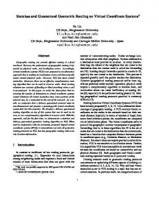
Figure 1: Coordination system setup. Each userselected vertex anchor broadcasts a single setup packet. Each node retransmits and updates its distance from the corresponding anchor, measured in hops traversed.
NODE MEMORY
CORONA Additions SETUP 1/0 (1-bit flag)
ANCHOR_A (2-bit flag)
ANCHOR_B (2-bit flag)
Meaning of Flag Combination
0
0
SET_ANCHOR_1
0
1
SET_ANCHOR_2
1
0
SET_ANCHOR_3
1
1
SET_ANCHOR_4
ANCHOR_ID
N_HOPS
{SOURCE}
{RECEIVER}
NHOPS
00
int
01
int
10
int
11
int
Figure 2: CORONA requirements in terms of packet header additions (left) and node memory (right)
The proposed coordinate assignment system relies on standard triangulation, popularized in several systems and studies [3]. An example and an overview of the assumed system is given in Fig. 1. We assume a rectangular area over which a large set of nanonodes is uniformly placed. The layout may be pre-arranged or random, provided that the average node density remains uniform over the surface. This layout is important for monitoring and controlling industrial and artificial materials [9]. The coordinates of a node comprise four parts, each corresponding to the distance of the node from the four anchors placed at the area vertexes. For example, the concentric arcs in Fig. 1 roughly correspond to the hop distance between anchor 1 and every node in the network. Therefore, according to CORONA, each node must obtain its distance from the anchor 1 -anchor 4 nodes. We note that the indexing of the anchors must follow a clockwise or counter-clockwise order. This is accomplished during a setup phase, during which the anchor nodes sequentially transmit a single packet with special flags sets. The receiving nodes are thus notified to update their observed hop count from the corresponding anchor and re-transmit the packet. The necessary packet headers and node fields are given in Fig. 2. When an anchor node, e.g. anchor 1 is to execute its part in the setup process, it sets the SETUP packet flag to 1, and ANCHOR A to the SET ANCHOR 1 value (0, 0). (The ANCHOR B field is used in the routing process, discussed below). Next, it sets the N HOPS field to one and
Figure 3: Using facing anchor points for packet routing may disallow the communication between certain network areas. broadcasts the packet. Each receiving node understands via the SETUP flag that the packet serves initialization purposes. It proceeds to read the ANCHOR A value and sets the corresponding distance in its memory to the N HOPS value. It then increases N HOPS by one unit and retransmits the packet. In this manner, all nodes are informed of the distance from anchor 1. After a safe timeout, the process is repeated for anchor 2 to anchor-4, concluding the setup process. Note that, the hop count address information defines an ”area” of the topology. The amount of nodes being in an area depends on i) the type of the topology and ii) the transmission range of each nanonode.
3.2
The Packet Routing Process
A triangulation-based coordinate system on a 2D plane requires three anchors to uniquely identify an area. However, given that CORONA assumes rectangular areas with anchors placed at the vertexes, even two anchors may suffice, because an area with theoretically duplicate coordinates usually lies outside the network. Even if both areas with identical coordinates would happen to lie within the network area, the result would just be a temporary increase in the number of retransmitting nodes. However, in the case of CORONA this is avoided altogether, as explained later. Therefore, the routing process of CORONA uses only two of the four anchor coordinates for each packet transmission. The decision is taken by the source node S based on which pair of anchors yields the lowest number of hops for transferring a packet, pkt, from a source node S with coordinates (s1 , s2 , s3 , s4 ) to a receiver node R with coordinates (r1 , r2 , r3 , r4 ). Once the appropriate anchor pair, (anchor i, anchor j) is chosen by the sender, the transmission process is initiated. The SETUP flag of the originating packet is set to 0 and the values of ANCHOR A and ANCHOR B flags are set according to the selected anchors for routing. Upon the reception of a packet a node T with coordinates (t1 , t2 , t3 , t4 ) deduces whether to retransmit a packet or not based only on simple integer comparisons: (ti ∈ [si , ri ]) && (tj ∈ [sj , rj ])
(1)
The criterion (1) essentially states that the retransmitting nodes lie within the area defined as the intersection of the rings:
1. Radius ∈ [si , ri ], Center = anchor i . 2. Radius ∈ [sj , rj ], Center = anchor j . It is critical, however, that the intersection of the two rings be a connected area. The opposite would disallow the communication between nodes S and R. It is not difficult to show that this condition always holds when the anchors are placed on non-diagonally-facing vertexes. In these cases, all concentric circles have a single common point within the rectangle area. This does not always hold for diagonallyfacing anchors. An example is given in Fig. 3, where the use of the top-right and bottom-left anchors bans the communication between areas A and B, since the ring intersection is segmented.
Table 1: Simulation Parameters Parameter Value Frequency 100GHz Normal Tx Power (PT X ) 2 dBnW Noise Level 0 dBnW Node Sensitivity (SIN Rthresh ) −10dB Attenuation Model Free Space (FSPL) Guard Interval 0.1 nsec Packet Inter-arrival 100 nsec Packet Duration 10 nsec 80 70
2. Obtain the optimal pair as follows: n o p∗ = argminpk Dpanchor i + Dpanchor j , k = 1 . . . 4 k
(2) Step 1 essentially provides a metric of hop-distance between S and R per coordinate, while step 2 chooses the two coordinates that offer the smallest aggregate distance in hops. The sender S then proceeds to transmit its packet as described.
4.
SIMULATIONS
In this Section we evaluate the performance of the proposed CORONA scheme versus alternative solutions. Particularly, CORONA is compared to the Dynamic Infrastructure (DIF) scheme of [15] and a probabilistic flood approach (FLOOD, e.g. [18]). The simulations consider 2D topologies, namely a uniform grid and a uniform random layout, and 10, 000 nodes. The selected layouts fill a fixed, square area, with dimensions 10 × 10mm. All subsequent runs consider a square area with four anchor nodes at the four corners/vertexes for CORONA. The physical-layer parameters are summarized in Table 1 and are typical for studies on nano-networks [6]. We employ the SINR approach to simulate the packet reception process [4]. The connectivity of the nodes is circular, assuming the use of a patch antenna [7]. In each case, the connectivity radius is defined by the Tx Power, the Noise Level, the SIN Rthresh and the attenuation model (FSPL): P (radius) < SIN Rthresh ⇒ N oise Level PT X < SIN Rthresh ⇒ F SP L(radius) · N oiseLevel r PT X c radius < · SIN Rthresh · N oiseLevel 4π · F
50 40 30 20 10
0 0 2000 4000 6000 8000 10000 Retransmissions per point−to−point packet exchange.
1. Calculate Di = |si − ri | , i = 1 . . . 4.
k
PDF (%)
60
Therefore, a sender S needs only consider anchor pairs that lie on the same side of the rectangle area, namely the pairs p1 = {anchor 1, anchor 2}, p2 = {anchor 2, anchor 3}, p3 = {anchor 3, anchor 4} and p4 = {anchor 4, anchor 1}. As stated, the selection criterion is based on which pair offers the smallest number of hops to reach the destination R. This can be expressed via the following lightweight process:
CORONA DIF FLOOD−0.4 FLOOD−0.6 FLOOD−0.8 FLOOD−1.0
(3)
Figure 4: Probability distribution function (PDF) of nodes involved in the transmission of a packet from a random source to a random destination. A grid topology is used.
where F is the operating frequency and c the speed of light in vacuum. A Guard Interval of 0.1nm is assumed, meaning that multiple receptions of the same packet arriving within this interval add up to the power of the useful signal. All DIF-specific parameters are taken from [15]. We allow for a 3µsec warm-up for all compared schemes. Then, with an inter-arrival time of 100nsec, we randomly select a sender and a receiver among the nodes. The sender sends a single packet, which is transferred to the receiver in a manner defined by each compared scheme. We repeat this process for 100 random pairs and we log: • The successful point-to-point packet exchange ratio (i.e. how many out of the 100 pairs communicated successfully). • The number of retransmitting nodes involved per each of the 100 packet exchanges, forming a probability distribution function (PDF). • The network-wide (i.e. global) i) packet retransmission rate, ii) successful packet reception rate, iii) packet loss rate. These metrics are defined as the aggregates over all nodes and over all 100 exchanges, divided by the duration of the simulation (i.e. the time for 100 exchanges) minus the warm-up period. Figures 4 and 5 present the results pertaining to the grid layout. The PDF of nodes involved per transmission pair
Grid Topology 50
CORONA DIF FLOOD−0.4 FLOOD−0.6 FLOOD−0.8 FLOOD−1.0
Global Pkt Retransm. rate. (Pkts/nsec)
37 25 12 50
37
25
Global Pkt Recv rate. (Pkts/nsec)
12 0.25
0.5
0.74
0.99
Successful point−to−point packet exch. (%)
300 610 910
Global Pkt loss rate. (Pkts/nsec)
1200
Figure 5: Radar plot for the setup of Fig. 4, presenting the successful packet transmission ratio, as well as the global packet send/receive/loss rate.
70
CORONA DIF FLOOD−0.4 FLOOD−0.6 FLOOD−0.8 FLOOD−1.0
60
PDF (%)
50 40 30 20 10
0 0 2000 4000 6000 8000 10000 Retransmissions per point−to−point packet exchange.
Figure 6: PDF of nodes involved in the transmission of a packet from a random source to a random destination, assuming a random topology.
Random Topology 50
CORONA DIF FLOOD−0.4 FLOOD−0.6 FLOOD−0.8 FLOOD−1.0
Global Pkt Retransm. rate. (Pkts/nsec)
37 25 12
Global Pkt 50 Recv rate. (Pkts/nsec)
37
25
12 0.25
0.5
0.74
0.99
Successful point−to−point packet exch. (%)
330 660 980 1300
Global Pkt loss rate. (Pkts/nsec)
Figure 7: Radar plot for the setup of Fig. 6, presenting the successful packet transmission ratio, as well as the global packet send/receive/loss rate.
is given in Fig. 4. It is obvious that the FLOOD approach involves every single of the 10, 000 nodes in the network, for each transmission pair, when the flood probability is 1.0 (FLOOD-1.0). This number drops proportionally to the flood probability, when the latter is decreased to p = 0.8, 0.6, 0.4 respectively. Notice that the respective PDFs are narrow peaks around the means defined by p × 10, 000. We remark that p is a parameter that requires manual, precise tuning, which may not be viable for nanonetworks. For example, Fig. 5 demonstrates that even wild variations of p may offer small performance advantage. All compared FLOOD variations and DIF achieve perfect packet exchange ratio (100%), but with a global packet reception rate almost five times higher than CORONA. Furthermore, FLOOD incurs the highest global packet retransmission and packet loss rates. This is expected, given that all nodes blindly participate in every packet exchange. Understandably, this performance can be crippling for the very limited power supply of the nanonodes. The DIF scheme performs much better than FLOOD in every case, without requiring any tuning. However, in Fig. 4 we notice that the corresponding PDF is a very narrow peak around an average of ∼ 1200 retransmissions. This number is approximately equal to the number of nodes elected to serve as retransmitters by the DIF scheme. In other words, for each random sender-receiver pair, the complete Dynamic Infrastructure participates to the packet transmission process. In turn, this may quickly deplete the nodes serving as retransmitters (infrastructures), since they handle all the packet transmission load of the network. (We notice, however, that once depleted, these nodes are automatically substituted by others). Nonetheless, the performance of DIF surpasses FLOOD in every aspect shown in Fig. 5. On the other hand, CORONA exhibits interesting traits. In Fig. 4 we observe that the PDF of CORONA is not a narrow peak, meaning that the number of retransmitters participating to a packet exchange varies considerably. This is expected, given that the packets now travel over paths defined by their coordinate system, as described in Section 3. In essence, the performance of DIF corresponds roughly to an average scenario for CORONA from this aspect. However, shorter paths are more probable for CORONA, as shown by the form of the corresponding PDF. Furthermore, Fig. 5 shows that CORONA combines a perfect packet exchange ratio (100%) with a considerably reduced global packet send, receive and interference rate. The gains of CORONA over FLOOD and DIF also validate the shorterpacket-path claim. In terms of global packet interference and send rate, DIF and CORONA behave similarly in the grid layout assumed in Fig. 5. These metrics are representative of the energy-efficiency of the schemes. However, the global packet reception rate is much lower for CORONA. This metric expresses the communication multiplexing potential. In essence, for each packet exchange, DIF involves approximately five times more (redundant) auditors than CORONA. This means that in the case of simultaneous packet exchanges among multiple sender-receiver pairs, DIF would be expected to cause unnecessary interference, limiting the multiplexing potential of the wireless medium. Finally, in Fig. 6 and 7 we study the same metrics in a ran-
dom node layout. The relative performance of the compared schemes is retained, but the difference between CORONA and DIF increases to the benefit of the proposed scheme. In random layouts, the pattern of retransmitters chosen by DIF is no longer well-formed (i.e. symmetric), while the number of retransmitters also increases [10, 15]. This naturally translates to more nodes involved pair packet exchange (Fig. 6) and higher global packet send and interference rates (Fig. 7).
5.
CONCLUSION
The present study introduced a joint coordinate and routing system for trustworthy nanonetworks (CORONA). CORONA uses distances from user-selected anchor points to define arc-shaped paths among any pair of nodes. These paths were shown to efficiently serve point-to-point communication needs, while reducing considerably the number of required packet retransmissions, promoting energy-efficiency in the highly restricted nano-environment. Future work is directed towards extensions to 3D topologies, where further investigation is required to define the optimal anchors for each sender-receiver pair. Finally, the use of ray-tracing techniques for more realistic simulations of the physical layer is a work in progress, with a particular interest in periodic topologies.
[8]
[9]
[10]
[11]
[12]
6.
ACKNOWLEDGMENTS
This work was supported by the EU FP7 OPTET project (Grant no.317631) and the GSRT in Greece with a Research Excellence grant. [13]
7.
REFERENCES
[1] I. F. Akyildiz and J. M. Jornet. Electromagnetic wireless nanosensor networks. Nano Communication Networks, 1(1):3–19, 2010. [2] P. Boronin, V. Petrov, D. Moltchanov, Y. Koucheryavy, and J. M. Jornet. Capacity and Throughput Analysis of Nanoscale Machine Communication through Transparency Windows in the Terahertz Band. Nano Communication Networks, 5(3):72–82, 2014. [3] A. Caruso, S. Chessa, S. De, and A. Urpi. Gps free coordinate assignment and routing in wireless sensor networks. In INFOCOM 2005. 24th Annual Joint Conference of the IEEE Computer and Communications Societies. Proceedings IEEE, volume 1, pages 150–160. IEEE, 2005. [4] A. Iyer, C. Rosenberg, and A. Karnik. What is the right model for wireless channel interference? IEEE Transactions on Wireless Communications, 8(5):2662–2671, 2009. [5] J. M. Jornet and I. F. Akyildiz. Channel Modeling and Capacity Analysis for Electromagnetic Wireless Nanonetworks in the Terahertz Band. IEEE Transactions on Wireless Communications, 10(10):3211–3221, 2011. ˜ Pareta. [6] J. M. Jornet, J. Capdevila Pujol, and J. SolAl’ PHLAME: A Physical Layer Aware MAC protocol for Electromagnetic nanonetworks in the Terahertz Band. Nano Communication Networks, 3(1):74–81, 2012. [7] K. Kantelis, S. A. Amanatiadis, C. K. Liaskos, N. V. Kantartzis, N. Konofaos, P. Nicopolitidis, and G. I.
[14]
[15]
[16]
[17]
[18]
Papadimitriou. On the Use of FDTD and Ray-Tracing Schemes in the Nanonetwork Environment. IEEE Communications Letters, 18(10):1823–1826, 2014. H. Kodesh, V. Bahl, T. Imielinski, M. Steenstrup, S.-Y. Ni, Y.-C. Tseng, Y.-S. Chen, and J.-P. Sheu. The broadcast storm problem in a mobile ad hoc network. In Proceedings of the 5th annual ACM/IEEE international conference on Mobile computing and networking - MobiCom ’99, Seattle, Washington, August, pages 151–162. ACM Press, 1999. C. Liaskos, A. Tsioliaridou, A. Pitsillides, I. F.Akyildiz, N. Kantartzis, A. Lalas, X. Dimitropoulos, S. Ioannidis, M. Kafesaki, and C. Soukoulis. Design and Development of Software Defined Metamaterials for Nanonetworks, 2015. IEEE Circuits and Systems Magazine. To appear. C. K. Liaskos and A. N. Tsioliaridou. A Promise of Realizable, Ultra-Scalable Communications at nano-Scale: A multi-Modal nano-Machine Architecture. IEEE Transactions on Computers, PrePrint(99):1–14, 2014. M. Pierobon and I. F. Akyildiz. Diffusion-Based Noise Analysis for Molecular Communication in Nanonetworks. IEEE Transactions on Signal Processing, 59(6):2532–2547, 2011. M. Pierobon, J. M. Jornet, N. Akkari, S. Almasri, and I.F. Akyildiz. A routing framework for energy harvesting wireless nanosensor networks in the Terahertz Band. Wireless Networks, 20(5):1169–1183, 2014. Shahram Mohrehkesh and Michele C. Weigle. RIH-MAC: Receiver-Initiated Harvesting-aware MAC for NanoN]etworks. In Proceedings of the ACM International Conference on Nanoscale Computing and Communication, pages 180–188. ACM, 2014. V. Srikanth, S. Chaluvadi, Vani, and Venkatesh. Energy Efficient, Scalable and Reliable MAC Protocol for Electromagnetic Communication among Nano Devices. International Journal of Distributed and Parallel Systems, 3(1):249–256, 2012. A. Tsioliaridou, C. Liaskos, S. Ioannidis, X. Dimitropoulos, and A. Pitsillides. Mitigating the broadcast storm in nanonetworks with 16-bits, Foundation of Research and Technology - Hellas, TR-TNL-IRG-2015-1, 2015. B. D. Unluturk, D. Malak, and O. B. Akan. Rate-Delay Tradeoff With Network Coding in Molecular Nanonetworks. IEEE Transactions on Nanotechnology, 12(2):120–128, 2013. P. Wang, J. M. Jornet, M. Abbas Malik, E. Fadel, and I. F. Akyildiz. Energy and spectrum-aware MAC protocol for perpetual wireless nanosensor networks in the Terahertz Band. Ad Hoc Networks, 11(8):2541–2555, 2013. T. Zhu, Z. Zhong, T. He, and Z.-L. Zhang. Achieving Efficient Flooding by Utilizing Link Correlation in Wireless Sensor Networks. IEEE/ACM Transactions on Networking, 21(1):121–134, 2013.