ABSTRACT. In this paper, counting objects techniques are proposed for fast pattern matching algorithm based on normalized cross correlation and convolution ...
International Journal of Applied Information Systems (IJAIS) – ISSN : 2249-0868 Foundation of Computer Science FCS, New York, USA Volume 5 – No. 8, June 2013 – www.ijais.org
Counting Objects using Convolution based Pattern Matching Technique Jaydeo K. Dharpure
M. B. Potdar, Ph.D
Manoj Pandya
School of Electronics, Devi Ahilya University (DAVV), Indore, Madhya Pradesh, India
Bhaskaracharya Institute for Space Applications and GeoInformatics (BISAG), Gandhinagar, Gujarat, India
Bhaskaracharya Institute for Space Applications and GeoInformatics (BISAG), Gandhinagar, Gujarat, India
ABSTRACT In this paper, counting objects techniques are proposed for fast pattern matching algorithm based on normalized cross correlation and convolution technique which are widely used in image processing application. Pattern matching can be used to recognize and/or locate specific objects in an image. It is one of the emerging areas in computational object counting. In this paper, introduces a new pattern matching technique called convolution based on pattern matching algorithm. Many different pattern matching techniques have been developed but more efficient and robust methods are needed. The pattern matching algorithm is used to identify the patterns similar present in image. With the patterns, identify the similarity measures of the given pattern to count the object present in the given image. An experimental evaluation is carried out to estimate the performance of the proposed efficient pattern matching algorithm for remote sensing as well as common images in terms of estimation of execution times, efficiency and compared the results with an existing conventional methods.
Keywords Convolution, Normalized Cross Correlation, Matching, Thresholding and Template Matching.
Pattern
1. INTRODUCTION Pattern matching is a significant job of the prototype detection process in today's world for eradicating the structural and efficient activities in a given image. Even though the pattern matching techniques is normally utilized in information processing and computer vision, it can be established in daily tasks. Template matching is conceptually a simple process, this need to match a template to an image where the template pattern is a part of the source image that contains the shape inside it. For this, the template image is shifted u-step in the xdirection and v-step in the y-direction of the image, and then the comparison is calculated over the template area of each position (u, v). The procedure is repeated for the entire image, and the template pattern that led to best match, the peak value, is defined to be the point where the shape (given by the template) lie within the source image. On the other hand, there are already many methods that have been proposed for speeding up the process of template matching [1], [2], [6], [9], [10]. The standard way of matching features between two images is known as pattern matching. This approach involves taking a given pattern in one image and shifting a template containing the same pattern in another image until the best comparison is found. The most common
and effective way of doing this task is by Normalized Cross Correlation (NCC) methods [7], which have a significant advantage over standard cross correlation (CC) methods, this technique is generally immune to noise and different lighting conditions across an image. Furthermore, the NCC is confined in the range between –1.0 and 1.0. So the setting of detection threshold value is much easier than the cross correlation, But it suffers from high computational complexity caused by summations over the entire template and computation time increases dramatically as the window size of the template gets larger. So we proposed a fast normalized correlation coefficient method based on convolution. Pattern recognition algorithm in optical camera image processing are applied to the remote sensing image because the improvement of the spatial resolution of image in today‟s world. but there are several different problem faced to remote sensing image processing and optical camera image processing, 1) the spatial resolution of remote sensing image is relatively low although much improved; 2) the remote sensing images are acquired images with different viewpoint angle, altitude and view field; 3) the SNR of the image is relatively low; 4) the object in remote sensing image usually has scale, translation and distortion; 5) the ratio of the number of object pixel and whole image pixel is quite small. Because the object on the earth are quite varying, from a large object to a small object, and one object has different appearance on the remote sensing image from other object because of different view point, view field, view angle and different climate condition. Therefore, all above problem result in the poor efficiency of template matching algorithm. It is a difficult thing to find a similar type of object in a large remote sensing image, and it is also a tedious work to search the object by matching the object template image to the given source image. It is necessary to find the most possible parts in which the object exists. This problem can be solved by using template matching techniques. In object recognition or pattern matching applications, one finds an instance of a small reference template in a large scene image by sliding the template window in a pixel-by-pixel basis, and computing the normalized correlation between them. The template is taken from source image with proper orientation. On the base of analysis of the conventional methods [4] for information extracting from the remote sensing image, a method of extraction particular object in remote sensing image based on pattern matching method is proposed. The method includes three parts: 1) building the template (desired pattern is taken from source image); 2) applying correlation
14
method between template and source image; 3) best match to show the possible pattern. The methods are applied to several high spatial resolution images i.e. finding building; tree and vehicles as example object in the image are extracted and recognized. Those examples evaluate that the method proposed in this paper is effective and accurate. Correlation-based methods have been used extensively for a variety of applications such as motion analysis [5, 12], object recognition [1], face detection [8, 15], printed characters, industrial inspections of printed-circuit boards [14], surfacemounted devices, wafers [3], medical field [11], ceramic tiles etc. The conventional normalized correlation method does not meet speed requirements for industry applications, so always required desirable high speed method for better accuracy. Template matching is performed on either bi-level image (black and white) or grey level image depends on the application.
( I (u, v))
3. EXISTING METHOD 3.1 Pattern Matching using Normalized Cross-correlation NCC method is a simple template matching method that determines the location of a desired pattern represented by a template function, T, inside a two dimensional image function I, the template image is scanned across the image forming a correlation plane that provides information of where the template best matches the image. Highest correlation value will indicate the location of the targeted object. To search the template in the image I ( x, y) of size m x m y pixels where I at the intensity ( x, y ) where x {1,..., mx } and y {1,..., m y } . Similarly the template T ( x, y) of size n x n y pixels where
n x mx and n y m y . NCC is evaluated at every point (u, v) for I and T, which has been shifted over the original image I ( x, y) by u- steps in the x - direction and v - steps in the y - direction. All the NCC coefficients are stored in a correlation matrix (u, v) can be written as:
(u, v)
[ I ( x, y) ( I (u, v))].[T ( x u, y v) (T )] x
y
(1)
I ( x, y) x
For the denominator, which normalized the cross-correlation coefficient, at every point (u, v) ,
u {1,..., mx nx 1} and v {1,..., m y n y 1} of the image, at which (u, v) is determined, energy of the zero mean image is defined as:
ei (u, v) [ I ( x, y) ( I (u, v))]2 x
x
Where
y
x
y
u {1,..., mx nx 1} and v {1,..., m y n y 1} and
( I (u, v)) is the mean value of I ( x, y) within the template T shifted by (u, v) steps and can be defined as:
(3)
y
And the zero mean ei (u, v) of the image within the area of the template function ( I (u, v)) have to be recalculated. The energy of the zero mean template function is defined as:
et (u, v) [T ( x u, y u ) (T )]2 (4) x
y
And the zero mean et (u, v)
of the template function
(T ) have to be pre-calculated only once. The value of this coefficient (u, v) (from equation 1) falls into the range [-1.0, 1.0]; a value of 1.0 corresponds to a perfect match. A threshold value has to be decided, a value above this threshold will be used to count the number of objects inside the source image.
4. PROPOSED ALGORITHM 4.1 Pattern Matching using Convolution This method includes a simple but fast correlation based template matching algorithm. The correlation coefficient calculation is implemented with convolution technique. In this technique for template matching purpose is only considerations on controlling the boundary and selecting region of interest on the source image. However, by using convolution technique, the template matching speed has been accelerated and the computational time has reduced to a reasonable value.
4.1.1 Calculation of the denominator To simplify the calculation of the denominator of the normalized correlation coefficient (from equation 1), the key idea is to use the standard deviation of image function I ( x, y) and standard deviation of the template function T (u, v) is calculated over the template image. The standard deviation of the image function can be defined by:
[ I ( x, y) ( I (u, v))]
2
[ I[( x, y) ( I (u, v)]2 . [T ( x u, y v) (T )]2
(2)
y
Similarly (T ) is the average value of the template image T is calculated. The denominator in equation (1) is the variance of the zero mean image function I ( x, y) ( I (u, v)) and shifted zero mean template function T ( x u, y v) (T ) due to this normalization, (u, v) is independent to changes in the brightness or contrast of the image.
2. OBJECTIVE Pattern matching techniques is used to count number of objects that are present inside the image, where the similar pattern is found. This method is applied on remote sensing as well as common images. The normalized cross correlation has been used extensively for many machine vision applications, but the traditional normalized correlation operation does not meet speed requirements for time-critical applications. So this proposed fast normalized correlation coefficient algorithm method is based on convolution, and is efficient for high speed application.
1 nx n y
x
y
[ I ( x, y)]
2
x
y
2 ( I (u, v)) I ( x, y)
[ ( I (u, v)]
x
2
x
y
(5)
y
And equations used in this model are the double sum evaluated over the region of the template which means
15
u x u n x 1 and v y v n y 1 . The third term of the equation (5) is written as:
[ ( I (u, v))]
2
x
x
1 nx n y
nx n y [
y
I ( x, y)] x
y
2
(6)
Can be simplified as the equation (5) is defined as:
[ I ( x, y) ( I (u, v))]
2
x
2
x
y
1 [ I ( x, y)]2 nx n y x y
x
y
(7)
So equation (8) defined in term of standard deviation is: (9)
The standard deviation i (u, v) of the image function has to be calculated only once by using convolution function, size of the function has same as the source image. Similarly the standard deviation of the template function can be written as:
Dt
nx n y
i
j
[T (i, j ) (T )]2 nx n y
(10)
So equation (10) defined in term of standard deviation is:
Dt nx n y t
(11)
Where i {1,..., nx } and j {1,..., n y } is same as the template size; this standard deviation t of the template function has to be pre-calculated only once. Moreover, both equations (9) and (11) have to be used for calculating the correlation coefficient.
4.1.2 Calculation of the Numerator A significantly and more efficient way of calculating the correlation coefficient is by computing the numerator of Equation (1) via convolution. The algorithm presented in the last subsection allows efficient calculation of the denominator. The numerator calculation is done by cross correlation of two functions (source image and template image) using convolution techniques. Therefore, further simplification of this calculation is required. The numerator should be written as:
N (u, v)
[ I ( x, y) ( I (u, v))].T ( x u, y v) (12)
x
y
Where T ( x u, y v) is a zero mean template function has to be defined by:
T ( x u, y v) T ( x u, y v) (T ) For simplifying the equation (13) can be written as:
N (u, v) I ( x, y).T ( x u, y v) x
y
y
N (u, v) I ( x, y).T ( x u, y v) x
[ I ( x, y)]2 I ( x, y ) 2 (8) [ ] nx n y n x y x ny
Di (u, v) n x n y i (u, v)
Since T ( x u, y v) has zero mean value of the template function and thus also their summation is zero, the term ( I (u, v)) T ( x u, y v) is zero as well. So this x
Equation (7) is used for calculating the standard deviation of the image function over the template is simply multiply and divide the nx n y is written as:
Di (u, v) n x n y
(14)
y
term can be neglected in equation (14), therefore the numerator term can be written as:
y
[ I ( x, y)]
( I (u, v)) T ( x u, y v)
(13)
(15)
y
The numerator term N (u, v) of the equation (15) is calculated simply shifted the zeros mean template over the image function I ( x, y) by u -step in x-direction and v-shift in ydirection by using convolution, size of this function has same as source image. Equations (9), (11) and (15) are used to modify the equation (1) for normalized correlation coefficient calculation, then the approximated correlation coefficient function can be defined by:
(u, v)
N (u, v) Di (u, v) Dt
(16)
Where u {1,..., mx n x 1} and v {1,..., m y n y 1} The template T ( x u, y v) is moved across image I ( x, y) in (u, v) plane and the correlation for each point is calculated. After complete scanning the related area, the highest correlation value representing the location of the target is obtained. Thus, position of the targeted pattern is known and its will be displayed. The range for the Correlation coefficient (from equation 16) (u, v) is confined in the range between -1.0 and 1.0. The Value 1.0 to indicate the maximum correlation of source image and template image.
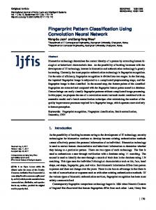
5. EXPERIMENTAL RESULTS 5.1 Object Counting Pattern matching experiments have been tested with several images and templates, which can be used for the application of finding different types of similar pattern inside the image. Many types of images are being used in this experiment where each image is different from another i.e. common as well as remote sensing images. All images and their template size are different because it is dependent on the object size which is used for counting purpose. There are some images as shown in Figures 1 (b) and 2 (b). In every test image the sub-image used as template as shown in figures 1(a) and 2(a), correlation graph is also shown in the figures 1(c) and 2(c). For each pattern, one template image has to be selected for testing. With the given test image, the image has to match with the template images and find the most similar pattern inside the image and using threshold value find out the number of objects. The matching experiment is performed for all of the many test images, and the number of objects and execution time has been recorded. Pattern Search: The normalized correlation method allows for stable pattern matching without being affected by ambient light. Following pictures show the average brightness of the whole image i.e. subtracted from the brightness (gray scale data) of each pixel for both the source image and template image. This is called normalization, which eliminates the difference in the brightness of both whole images. Then, the
16
template image is located at the position where the patterns of the reference and input images best match (i.e. highest correlation), and the position of the target pattern in the image is accurately detected as shown in figure 1(c) and 2(c).
(a) Template
(a) Template
(b) Remote sensing image
(b) Source image
(c) Correlation graph image Figure 2: Remote sensing image containing the template pattern (c) Correlation graph image Figure 1: Common image containing the template pattern
Table 1: Counting Object by using NCC and proposed algorithm in images NCC (Count Object) Execution Counted Time Object (sec) 8 1.74
Convolution (Count Object) Execution Counted Time Object (sec) 8 0.03
Sr. no.
Name of Object
Image Size
Template Size
Actual No. of Object
1
Car
200x198
27x24
8
Coin
233x203
44x43
10
10
3.17
10
0.12
3
Building
267x262
41x48
11
12
3.92
12
0.16
4
Circle
245x364
24x29
5
5
2.03
5
0.50
5
Triangle
360x456
53x54
6
5
3.14
5
0.94
6
Tree
575x305
74x79
17
15
6.06
15
1.13
7
Car
630x545
45x39
14
14
7.03
14
2.14
8
Building
756x648
91x87
16
17
9.78
17
3.12
9
Building
864x708
89x90
13
11
10.05
11
3.22
2
17
10
Tree
923x896
72x82
15
Execution Time (Sec)
Proposed
10 8 6 4 2 0 2
3
4
5
6
16
4.23
This paper describes novel pattern matching algorithm, called NCC and Convolution which is to identify the feature spaces of the object present based on its similarity measure. The experimental results indicate that, both algorithms have same result with better accuracy and the proposed method has greater speed as compared to conventional method, so this method can be used for high speed industrial application. It is very simple and straight approach for finding the multiple patterns from a given image.
12
1
10.25
7. CONCLUSION
Time Efficiency NCC
16
7
8
9
10
Serial no. object
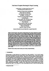
Figure 3: Performance comparison of time efficiency in NCC and proposed algorithms
But, this template matching method quickly fails by influence of disturbance, such as with illumination changes, and rotation of the object. For example, a circumstance where template matching can fail is when real world image objects sometimes have different appearance because of acquisition in outdoor settings affected by the changes in sun location and cloud cover etc.
8. FUTURE SCOPE Counting Objects
Actual Objects
NCC
This paper investigates the pattern matching algorithm to identify the feature spaces of the object present based on its similarity measures. A unique in its kind, this is the first different approach proposed to speed up the process of robust template matching. The method proposed in this paper gives useful scenario for solving this type of problem. These methods will be very helpful for pattern based classification and pattern based analysis in an image.
Proposed
Number of objects
20 15 10 5
9. ACKNOWLEDGEMENT
0
Authors would like to thanks T. P. Singh, Director, Bhaskaracharya Institute for Space Applications & Geoinformatics for constant encouragement to our research work.
1
2
3
4
5
6
7
8
9
10
Serial no. object
Figure 4: Performance comparison of counting objects in NCC and proposed algorithms
6. SIMULATED DATA To test the speed and accuracy of the convolution method versus the proposed method are evaluated, Tables 1 shows the CPU execution times and counting object for different image object and their size. Figure 3 shows the performance comparison of remote sensing and common images which is indicated that the proposed method has high speed of execution over conventional method. Figure 4 shows the graph between numbers of objects which are counted from both methods and serial number of objects which indicates that proposed and conventional method has same result with good accuracy. All simulations were done on Matlab using an AMD Phenom (tm) II X3 720 processor desktop with 2.80 GHz CPU and 1.75 GB of RAM. The features for representing the object are varying because there are so many different objects. Recognizing different objects from remote sensing image can‟t get a good result because of each object has different scale, rotation and illumination. But this can get a good distinction on counting objects just by proper thresholding, avoiding the difficulty of extracting the features and complexity of the correlating computation for searching those features in the input image
10. REFERENCES [1] D. M. Tsai, C. T. Lin, (2003). Fast normalized cross correlation for defect detection. Pattern Recognition. Letter. 24 (15), 2625–2631. [2] Di Stefano, L., Mattoccia, S., (2003) a. Fast template matching using bounded partial correlation. Mach. Vis. Appl. 13 (4), 213–221 [3] Federico Tombari, Stefano Mattoccia, Luigi Di Stefano, Fabio Regoli, and Riccardo Viti (2009), “A Template Analysis Methodology to Improve the Efficiency of Fast Matching Algorithms” Springer-Verlag Berlin Heidelberg, pp 100-108. [4] Gonzalez R.C., and Woods R.E. (2002) “Digital Image Processing” (Second Ed), Prentice Hall, ISBN-10: 0201180758. [5] James W. Davis Mark A. Keck, (2005) „A Two-Stage Template Approach to Person Detection in Thermal Imagery‟, Applications of Computer Vision, Breckenridge, Co, January 5-7. [6] Jiun-Hung Chen, Chu-Song Chen, and Yong-Sheng Chen (2003) “Fast Algorithm for Robust Template Matching With M-Estimators” IEEE Transactions On Signal Processing, Vol. 51, No. 1, pp - 230-243. [7] Kai Briechle and Uwe D. Hanebeck, “Template Matching using Fast Normalized Cross Correlation”,
18
Institute of the automatic control Engineering, 80290 Munchen, Germany. [8] Lim Huey Charn, Liyana Nuraini Rasid, Shahrel A. Suandi (2010) “A Study on the Effectiveness of Different Patch Size and Shape for Eyes and Mouth Detection” International Journal on Computer Science and Engineering Vol. 02, No. 03, pp. 424-432. [9] Luigi Di Stefano, Stefano Mattoccia and Federico Tombari (2005) ”ZNCC-based template matching using bounded partial correlation” Elsevier, Pattern Recognition Letters 26 pp. 2129–2134. [10] Mikhail J. Atallah (2001) “Faster Image Template Matching in the Sum of the Absolute Value of Differences Measure” IEEE Transactions On Image Processing, Vol. 10, No. 4, Pp. 663-659. [11] R. Harini and C. Chandrasekar (2012) “Efficient Pattern Matching Algorithm For Classified Brain Image” International Journal of Computer Applications (0975 – 8887) Volume 57– No.4.
[12] Rajiv Kumar Nath, „Road Vehicle/Object Detection And Tracking Using Template‟, Indian Journal Of Computer Science And Engineering Vol 1 No 2, ISSN: 0976-5166, pp. 98-107. [13] Raju Bhukya, DVLN Somayajulu (2011) “An Index Based Sequential Multiple Pattern Matching Algorithm Using Least Count”, International Conference on Life Science and Technology IPCBEE vol.3, IACSIT Press, Singapore, pp 109-113. [14] S. Hezel, A. Kugel, R. M.anner andD.M. Gavrila, (2002) „FPGA-based Template Matching using Distance Transforms‟, IEEE symposium on Field-Programmable Custom Computing Machine, Napa, USA. [15] Nadir Nourain Dawoud, Brahim Belhaouari Samir , Josefina Janier, (2011) “Fast Template Matching Method Based Optimized Sum of Absolute Difference Algorithm for Face Localization”, International Journal of Computer Applications (0975 – 8887) Volume 18– No.8, pp. 30-34.
19