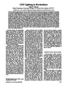
(d) Target image is a Mona Lisa paint. (e)-(f) Illumination patterns for the same working distances as (b) and (c). (e) Weights wi computed by the constricted LS ...
Creating a desired lighting pattern with an LED array Ivan Moreno Unidad Academica de Fisica, Universidad Autonoma de Zacatecas, 98060, Zacatecas, Mexico.
ABSTRACT An array of spatially distributed LEDs can produce a desired illumination pattern by individually modulating each LED. A target image can be the desired lighting pattern so that the software could find the best solution to match it. Given a desired illuminance distribution on a target surface, the luminous flux of each single LED that most closely matches the desired distribution must be determined. We review a constrained least squares method for this problem. We show how the quality of the rendering depends on the number of LEDs, array-target distance, and the size of the illuminated area. In particular, as we observed, there is an optimum illumination distance, which is proportional to the square root of the target size and varies inversely with a power of the number of LEDs. Key words: light-emitting diode, LED array, illumination distribution, least-square method, normalized-cross correlation.
1.
INTRODUCTION
The rapid development of LEDs over the last years has opened up new applications in general illumination. An interesting application is to use a cluster of LEDs for producing a given desired illuminance (or irradiance) distribution on a target (see Fig. 1). In general, a high power LED emits light into one hemisphere with some degree of directionality. As a consequence, LED arrays can be designed to easily direct emission into specific lighting patterns without additional optical devices. Such illumination system offers a high flexibility in rendering and changing the target illumination. An adaptive lighting pattern can be adjusted to specific environments and requirements by individually modulating the LEDs. This controllability can provide new benefits in numerous applications as lighting, displays, transportation, agriculture, and medicine.
Fig. 1. Cluster of LEDs projecting an arbitrary illumination distribution over a target surface.
Lighting applications include illuminated ceilings, interior design, lighting in buildings, and luminous signage.1 The flexibility of an LED array is absent in conventional light sources, because a fluorescent lamp cannot be dimmed, and an incandescent source decreases its efficiency and changes its spectral content when its intensity is dimmed. Moreover, a multicolor LED array can render a color illumination distribution. In other applications like high-contrast liquid crystal displays, spatially distributed LEDs in the backlight system can provide localized illumination effects that increase the image contrast, and reduce the light leakage in image regions that do not need illumination.2-4 An application beyond illumination and lighting involves specialized solid-state micro-projection devices, which contain up to several thousand individually-addressable micro-pixel elements emitting light in the ultraviolet or visible regions of the spectrum.5-8 These
8th International Conference on Solid State Lighting, Ian T. Ferguson, Tsunemasa Taguchi, Ian E. Ashdown, Seong-Ju Park, Editors, Proceedings of SPIE Vol. 7058 (2008) © 2008 SPIE ⋅ ISSN: 0277-786X (print) ⋅ $ 15.00
micro-LED arrays can project controllable illumination distributions into biological cells and tissues, biopolymers, and photoresists. This leads to new possibilities in optical microscopy, bio-sensing and chemical sensing, mask-free lithography and direct writing.5-8 An arbitrary image can be the target light distribution of the LED array. However, the pixels in that image cannot be used directly as intensity weights, since light beams overlap between neighboring LEDs. However, the luminous flux of each single LED that most closely matches the desired light distribution can be determined. In next section, we review a constrained least squares method for this problem. We analyze the effects on the rendering accuracy due to the number of LEDs, array-target distance, and the image size. The accuracy of rendering is evaluated by using normalized cross correlation, which measures the similarity between the target image and the rendered light distribution. As shown in Section 3, there is an optimum target-array spacing, which varies with the square root of the image size and varies inversely with a power (~0.5) of the number of LEDs.
2. CONSTRAINED LEAST SQUARES PROBLEM The problem is stated as follows: given a desired illumination distribution over a flat surface, determine the LED intensities that will most closely match it. In other words, given a desired image matrix IMAGE, determine the LED intensity levels that most closely approximate IMAGE. The general problem involves determining how many LEDs to use, where the LEDs must be placed, as well as the radiation pattern of LEDs. This general case is a non-linear optimization problem. However, if all LEDs are previously positioned, and their radiation patterns fixed, the calculation of the LED intensities is a linear optimization process. The LED radiation pattern is characterized by the angular intensity distribution. Radiant (or luminous) intensity is the radiant (or luminous) flux per solid angle [W/sr or lm/sr] in a given direction from the source. It is the radiometric standard used to rate spatial variation of LEDs. However, the power distribution that illuminates the target is characterized by the irradiance. Irradiance (or illuminance) is the radiant (or luminous) flux incident on a surface per unit area [W/m2 or lm/m2]. Consider Ei is the normalized irradiance (or illuminance) spatial distribution (in arbitrary units) of the i-th LED illuminating the target plane, where i=1,2,…N. Therefore [ E1, E2,.. EN ] is the set of functions resulting from an array of N LEDs illuminating the target (see Fig. 1). These functions can be easily modeled with Gaussians for any kind of LED of practical interest.9 The problem can be stated in terms of finding non-negative weights wi such that the irradiance produced by the LED array N
Earray ( x, y ) = ∑ wi Ei ( x, y ) ,
(1)
i =1
approximates a target image, IMAGE, we wish to approximate. The problem is one of least squares (LS), in which |IMAGE−Earray|2 must be minimized. The LS minimization process leads to solve a system of equations given by: N
H
V
H
V
∑∑∑ wi Ein,m E nj,m = ∑∑ IMAGEn,m E nj,m , i =1 n =1 m =1
(2)
n =1 m =1
where j=1,2,…N., and the target image size in pixels is NHV=H×V. This set of linear equations can be expressed as a matrix product:
⎡∑ H ∑V E1n ,m E1n ,m L ∑ H ∑V E1n ,m E Nn ,m ⎤ ⎡ w1 ⎤ ⎡∑ H ∑V IMAGEn ,m E1n ,m ⎤ n =1 m =1 ⎥ ⎥ ⎢ ⎥ ⎢ n =1 m =1 ⎢ n =1 m =1 M O M M ⎥ , ⎥⎢ M ⎥ = ⎢ ⎢ V H V H V n,m n,m n ,m n ,m ⎥ n,m ⎥ ⎢ ⎢ H L ∑n =1 ∑m =1 E N E N ⎢⎣ wN ⎥⎦ ∑n =1 ∑m =1 IMAGEn ,m E N E E1 n =1 ∑m =1 N ⎣∑ 3 ⎣14444 1 4444444442444444444 3⎦ 12 4244444 3⎦ W EE
IE
(3)
where EE is a symmetric matrix, i.e. EEi,j=EEj,i. Taking into account the symmetric nature of EE, its calculation time can be reduced by nearly half. Vector W gives the irradiance weights wi of LEDs in the array. The problem is to solve Eq. (3), which contains N linear equations in N unknowns. The problem of solving W cannot be based on a direct numerical method because the solution is not stable. This is due to the large number of unknowns and the difficulty of introducing physical constrains (in our case wi≥0). Therefore, an iterative numerical method must be used. We compared two simple methods: the Gauss-Seidel and successive over-relaxation (SOR). The Gauss-Seidel iteration is
IEi − ∑ j =1 EEi , j wkj +1 − ∑ j =i +1 EEi , j wkj i −1
wik +1 =
N
,
(4)
+ (1 − α )wik ,
(5)
EEi ,i
and the SOR iteration is
IEi − ∑ j =1 EEi , j wkj +1 − ∑ j =i +1 EEi , j wkj i −1
k +1 i
w
=
N
EEi ,i α
where α is a weighting factor for rapid convergence (0