IEEE INFOCOM 2011 Workshop on M2MCN-2011
Cross-layer Routing in Wireless Sensor Networks for Machine-to-Machine Intelligent Hazard Monitoring Applications Yuanyuan Zeng1,*, Naixue Xiong2,*, Laurence T. Yang3, Yan Zhang4 1 School of Electronic Information, Wuhan University, China email:
[email protected] 2 Department of Computer Science, Georgia State University, USA email:
[email protected] 3 Department of Computer Science, St. Francis Xavier University, Canada email:
[email protected] 4 Simula Research Laboratory, Martin Linges v 17, Fornebu, Norway email:
[email protected] *Yuanyuan Zeng and Naixue Xiong are correspondence authors Abstract—Machine-to-Machine (M2M) technologies allow network-to-device communications. M2M covers a wide scope of technologies including sensing and wireless networking protocols. Hazard monitoring applications based M2M such as monitoring using wireless sensor networks (WSNs) are challenged by realtime and interference-aware requirements. The designed communication mechanisms need to guarantee efficient M2M communication and performance management. In hazard monitoring applications, network topology changes rapidly due to device failures. Cross-layer design is an effective scheme to improve communication performance. In this paper, we propose a novel cross-layer mechanism with joint power control, dynamic link scheduling and routing (JPDSR) in hazard scenarios. The joint mechanism of routing, power control and link scheduling with double frame scheme guarantees a high probability of interference-aware and real-time data delivery in hazard according to event priorities. We conduct simulations and compare it with related work. The simulation results show that our routing has better performance that is more suitable for hazard monitoring applications.
Intelligent hazard monitoring applications using wireless sensor networks such as fire monitoring, earth quake monitoring and underground mine monitoring, etc, has highly time-critical and reliable communication requirements on data collections. Nowadays, there are many literatures dealing with real-time communications in general WSNs. Some of them propose to dynamically increase the transmission power to support real-time communication according to the deadline. But power increase brings more contentions in the networks, and degrades the network performance especially with big network workload. For intelligent hazard monitoring applications, the workload increases with more event data packets as hazard spreads in the surveillance area. Combining link scheduling with real-time routing seems a solution to achieve delay-bounded routing by avoiding possible interference. As hazard expands, the nodes die quickly in the network. The network becomes less connected or even partitioned. Then, it is difficult to find interference-aware and real-time routing even by using joint power control and link scheduling in the hazard scenarios. To address the above challenges, we propose a novel distributed cross-layer routing by joint together with power control, dynamic link scheduling (JPDSR). It aims to achieve real-time and interference-aware data delivery in M2M intelligent hazard monitoring applications. JPDSR utilizes dynamic link scheduling with double frame scheme based on event priorities, which provides more chances for urgent events to make real-time and reliable data delivery in hazard. Section II presents the related work. Section III is the problem definitions. We present the details of JPDSR in Section IV. Section V is simulation results. Finally, Section VI concludes this paper.
Keywords-cross-layer; routing; real-time; interference-aware; hazard monitoring; machine-to-machine; wireless sensor networks
I.
INTRODUCTION
Machine-to-Machine (M2M) communications and networking enable intelligent interconnecting of physical devices like sensors, and eventually create Internet of Things. As recent technology advances in areas such as sensing, networking, and actuating control, M2M communications become a new business concept borne from the original telemetry technology. They are used for automatic transmission and measurement of data from remote sources like remote wireless sensor networks. M2M covers a wide scope of technologies including sensing, communications, computing and control. It could utilize the ubiquitous cyberphysical networking systems to convey data readings and support diverse applications.
978-1-4244-9920-5/11/$26.00 ©2011 IEEE
II.
BACKGROUND AND RELATED WORK
Developments in machine-to-machine technology are opening up incredible opportunities for a wide range of
206
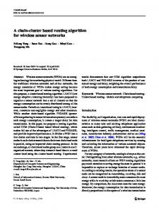
to collect and control the sensor data, which are called controllers. A directed graph G (V, E) is used to model the wireless sensor networks. Each sensor can adjust its transmission ranges to one of the k levels: r0, r1… rk-1=rmax by using different transmission power from p0, p1, till pk-1=pmax. Initially, all sensors work in p0. Tmax is the application-given maximum acceptable delay timeliness in reporting such a hazard event to a controller. Time is slotted into a non-overlapping equal time period called frame, which is divided into non-overlapping equal time periods called time slots. Each time slot is a time slice that is enough for a data packet transmission and corresponding ACK. Initially, each node has the same default frame structure with the same length. We define “Interference Area” (IA) as the maximal range that two concurrent transmissions would interfere with each other. For irregularity of radio, it is difficult to estimate IA by hops, because node a can reach node b does not mean node b can reach node a. To estimate IA approximately, we define “Possible Interference Area” (PIA) as 2-hop neighborhood. We define the frame structure as shown in Figure 1. Each frame includes the following three phases: The control phase: In this phase, a start beacon is broadcasted out to keep local synchronization and exchange newly assigned slots with its neighbors. In slot exchange messages among neighbors, each node exchanges the allocated slots of itself and its neighbors. In this case, each node knows the allocated slots information among its 2-hop neighborhood (i.e., PIA). During this phase, we use contention-based mechanism to access media. The schedule phase: Based on local allocated slots information in PIA, each node makes interference-aware link slot allocation by selecting the available slots according to flow demand. In this phase, the node schedules the allocated slots for current link. The ACK phase: In this phase, the node acknowledges the allocated slot. If there is no flow on the allocated slot for continuous frames, the slot can be recycled. If interference occurs on the allocated slot, then this slot is tagged as an “interference slot”. Then, the node chooses the other available slots in the next frame.
wireless data services and applications. Lawton et al [1] present the application growth of M2M communication technology for automated intelligent systems, in which sensors exchange and gather data between each other. Mitsui et al present [2] some basic M2M technologies for distributed sensor networking systems, which expect to be used in disaster prevention, environmental monitoring, etc. They propose that M2M technologies such as sensor network systems that enable machines to communicate with each other automatically. Many wireless sensor network applications require realtime communications. There are some real-time routing protocols designed for general sensor networks. For example, SPEED [3], MM-SPEED [4], and RPAR [5] are designed for real-time applications with explicit delay requirements. Beyond routing, medium Access Control (MAC) in wireless sensor networks plays an important role in successful communications. NAMA [6] and TRAMA [7] are such protocols that make collision-avoidance scheduling with node information of two communication hops away. It is shown to perform poorly in heavy load, because interference range is not the same as communication range. Sobral et al [8] propose hybrid contention/TDMA-based (HCT) MAC, which was specially designed to work with ad-hoc wireless networks organized in clusters, providing timely bounded communications both inside and outside the clusters by resource reservation. There are some literatures with cross-layer design. In [9], the authors propose a joint optimal scheduling, routing and power control that achieves max-min fair rate allocation in a multi-hop wireless network. Elbatt et al [10] propose a solution to the MAC layer in contention-based wireless ad-hoc networks by power control. The motivation is to limit multiuser interference to increase single-hop throughput and reduce power consumption. Kanzaki et al [11] propose a TDMA slot assignment protocol to improve the channel utilization by changing the frame length dynamically. Through the above mechanisms, it is still difficult to find an interference-aware and real-time route path in hazard scenarios. In our previous work, we propose a preliminary RTRR routing designed especially for building fire monitoring [12]. In the paper, the probability of end-to-end real-time communication is achieved by maintaining a desired delay based on message propagation delay estimate and power adaptation. Based on it, we propose a cross-layer mechanism by joint power control, link scheduling and routing together. III.
Figure1. The frame structure
PROBLEM DEFINITIONS
Each node has the same default frame structure. In hazard scenarios, the node could double the frame length as shown in Figure 2.
We use smart sensor devices based M2M system to monitor the hazard situations. Some devices such as actuators are used
Figure 2. The doubled frame structure
2
207
(1) To calculate the available slots: the slots not being used by the other links among the node’s PIA. (2) To calculate the time left for end-to-end packet delivery: slack. If satisfies slack – t_sche > 0, the link schedule is admitted. The link schedule time t_sche is calculated by: t_sche =tc+ts , where tc is the time waiting for the next link schedule. ts is the time of scheduling slots for current link. The number of allocated schedule slots needs to satisfy the link flow demand. (3) Each on-line link is allocated with the available slots for transmission. If the slots are not being used for continuous number of frames, it will be recycled for other transmissions. From the above, each link will always be activated in its allocated slots until no traffic on the link for several continuous frames, and then the slots are recycled. In the scheduling phase, the node tries to use the assigned slots for transmission if link admission is successful. If the real-time, interference-free slots are found and the number of slots is enough for traffic flow demand on the link, the link flow request is admitted. In the ACK phase, the node acknowledges the slot allocation toward its 2-hop neighbors. In this phase, we also deal with two problems: the slot recycling problem and the solution for interference problem. l The slot recycling problem: if some assigned slots are not used in certain number of continuous frames, we then recycle the slots (i.e., tag them as available slots). l The solution for interference problem: if current link collides in communication with the allocated slot, it implies that there are other interference links assigned with the same slot. The inference slot will be tagged. Then the link node chooses the other available slot in its next frame. This is because PIA is only an estimate of interference range, but not a real interference range because of radio asymmetry. From the above three phases, we could decide whether to admit or block an on-line route path. If a route path request with urgent data packets is blocked, we will use dynamic link scheduling with double frame scheme based on event priorities.
Except basic node and routing information (the same as described in RTRR), each sensor device maintains the following information locally: l The frame length and slot assignment information. l The slot assignment among its 2-hop neighbors (i.e., PIA). This can be achieved by message exchanges in the control phase. Dynamic link scheduling is defined as improved link scheduling using dynamic double frame scheme according to event priorities in hazard. We define two kinds of event priorities in hazard as: “high” and “ordinary”, respectively. We define the hazard event as “high” priority that occurs on some nodes that are in dangerous conditions, e.g., short of energy. Or, define the hazard event as “high” priority that occurs on nodes that placed on important positions, e.g., nodes placed in crowded venues and dangerous positions that will collapse in hazard very soon. The priority of events shows the different emergency levels for data delivery. In this case, the routing with a high priority event always has more advantages on real-time data delivery than an ordinary event. JPDSR tries to find a delay-bounded route by joint with power control and dynamic link scheduling according to the following rules: (1) It finds the route with minimal end-to-end power allocation on the route path link. (2) Each link on the route makes interference-free slot allocation with the power vector in (1). (3) The end-to-end delay of the route is within the given bound Tmax. (4) The node with the “high” priority event can double the frame when no outgoing link satisfied both power allocation and slot allocation by (1) and (2). It can halve its doubled frame when no slots are used in its doubled frame part. IV.
JPDSR PROTOCOL
A. Cross-layer Routing with admission control When the transmission power increases, the node gets a higher probability to find a real-time packet delivery within the given delay bound. But, it also brings more interference because of the increased interference range. When the power decreases, the network interference reduces too. It also reduces the probability to find a delay-bounded routing path. In JPDSR, we select the next hop according to routing metrics proposed in RTRR, i.e., select the next hop closer to the controller that satisfies delay estimate. For on-line route request in JPDSR, we use admission control to block or admit it. The admission control mechanism can be explained in the following phases. In the control phase, the node collects the slot assignment information in its interference range. Then it knows the slots that are available to assign. Two interference links cannot make assignment at the same time. For each outgoing link, we utilize link admission control to assign the minimal available slot that satisfies the delay requirement. Per-link admission control is executed according to the delay requirement and interference constraint as follows:
B. Dynamic link scheduling with double frame scheme If a node with high priority event data packets cannot find its next hop with interference-aware scheduling, then this node will broadcast out a request and try to double its frame. The double frame scheme request is piggybacked in the neighbor exchange message and broadcasted out in control phase of the frame. During the control phase, if the current node receives other requests from neighbors, only the one sent out earliest is admitted. The other requests will be blocked. The node doubles its frame will notify its 2-hop neighbors in the ACK phase. Accordingly, the 2-hop possible interference neighbors will update their frame length to keep local synchronization. For the synchronization problem of the 2-hop neighbors and their neighbors, the double frame scheme could guarantee that there is at least one successful synchronization chance during every two previous frames.
3
208
The JPDSR pseudocode describes the cross-layer routing. JPDSR pseudocode 1 For each node u selects the next hop by RTRR with pcur 2 If can reach v with pcur 3 If link_admission_control(e(u,v);pcur) 4 records assigned slots for e 5 return 6 else 7 do 8 increases pcur to pcur+1 to reach v’ 9 pcurß p cur+1 10 If link_admission_control(e (u,v’);pcur) 11 records assigned slots for e 12 return 13 endif 14 while pcurpmax && priority== “high” 16 do 17 pcur ß pmax 18 If !double_frame(e (u, v’)) 19 break 20 endif 21 while !link_admission_control (e(u, v’);pcur) 22 enddo 23 If link_admission_control(e(u,v);pcur) 24 records assigned slots for e 25 return 26 endif 27 endif 28 endif 29 endif 30 endfor 31 int double_frame(e (u,v)) 32 { 33 If current double request wins the tie 34 Frame_ length(u)= Frame_length(u)*2 35 Frame_length(v) = Frame_length(v)*2 36 else 37 return 0 38 endif 39 updates frame length among 2-hop neighbors 40 return 1 41 } 42 int link_admission_control(e(u,v);pi) 43 { 44 slot(e)ßsubset of (L\ slot(e’)) with size Flowe; 45 // L is the length of schedule phase in a frame 46 //e’ is the 2-hop neighborhood PIA links of e 47 s.t. 48 slack –t_sche > 0 49 If slot(e)!=Φ 50 return 1 51 else 52 return 0 53 endif 54 }
Line 1-30 is the JPDSR routing mechanism. Line 31-41 presents the function of doubling the node frame. Line 42-54 is the link admission control function. Line 1-6 describes that each node selects the next hop by RTRR until it cannot find the next hop with successful admission control. Line 7-14 shows the node increases its power level gradually to try to find an interference-aware next hop with a feasible schedule until it reaches pmax. Line 15-22 shows if the node reaches pmax without satisfying next hop and the event packet priority is high, we could try to double the node frame length continuously to find the satisfying next hop. In line 23-26, if finds a next hop with feasible schedule by using double frame scheme, the node records the slot information. Line 32-38 shows if current double request is admitted, then the nodes adjacent to the current link doubles the frame. Otherwise, the function returns 0 to imply the failure of double request. Line 39-41 shows if current link nodes double the frame, they should broadcast the notification among the 2-hop neighbors. The nodes that receive such messages will update their frame length to keep frame consistency and synchronization. Line 43-48 shows how to assign slots for current link e. In line 44, L\ Slot(e’) is the available slots except interference slots of current link. The size Flowe is the number of slots satisfying flow demand. Line 47-48 is constraint condition that time left for node data routing should be larger than link schedule time. Line 49-53 shows the return value of the function. If admission control is successful, the return value is 1. Otherwise, the return value is 0. The dynamic link scheduling with double frame helps to delivery the high priority data packets toward the controller with high probability of real-time and interference-aware routing. If a node finds the double frame part not being used for several continuous cycles, it halves the frame till its default frame length to provide more chances for other transmissions. C. An Illustration of JDPSR Figure 3 shows an illustration of JDPSR routing. We consider the case of routing CBR flow and one unit of slot for each link flow. The node g and node h are two controllers in a WSN. The other nodes are sensors. There are two power level could be used as: p1 and p2. To simplify the figure, we only show the scheduled phase in the frame. The arrow line labeled with power and slot number shows the scheduled link, while the dash line labeled with power shows the unscheduled link. Figure 3(a) shows routing from the node a to node g, while current node b makes on-line scheduling. For node g, it hears that slot 0, 1, 3 are unavailable from its 2-hop node a, b, c and e because of scheduled link pair (d,a;p1;1), (a,b;p1,0),(c,g;p1,3), (e,c;p1,0) accordingly. So, we choose slot 2 for link (b, g; p1). Figure 3(b) shows routing when node b dies in hazard. Then the adjacent link pair (a, b; p1;0) and (b,g;p1;2) fails. The node a increases its power to p2 and tries to find new neighbors to repair the route. Then we choose the next hop node c with link pair (a, c; p2) according to routing metrics. During the new neighbor discovery process, new neighbors are found by increased power. Then, the new neighbors send
4
209
reply to node a with the slots information by using power p2 temporarily. The node a knows slot 0, 2, 3 are interference slots (i.e., slots that are used by new neighbor node c, f and their neighbors). Then no slots can be scheduled for node a. If the event data packets routed from node a to g has “high” priority, we use double frame scheme on current link schedule. Figure 3(c) shows the details of doubling link scheduling with double frame scheme utilized by node a for routing from a to g. The node a doubles its frame length. Then it broadcasts a notification message to notify its 2-hop neighbors. The neighbors that receive the message will double their frame length to keep local consistency and synchronization. The node a chooses slot 4 for transmission that is an interferencefree and minimal-delay slot. If the schedule on link (a, c; p2, 4) satisfies delay constraint condition (i.e., slack – t_sche > 0), we then schedule it for data delivery. For node e, it then finds collision on slot 0 in ACK phase. It changes to use slot 1 for the next transmissions, and then notifies the receiver.
(a) routing from node a to g
(b)routing from node a to g when node b dies in hazard
(c) link scheduling with double frame scheme from node a to g Figure 3. Routing by joint with power control and dynamic link scheduling
V.
SIMULATIONS
The ns2 simulation is based on the parameters of the MICAz motes (the same as we use in RTRR). All nodes could be used to work with 3 power levels. The minimal power is the default power. We choose 100 devices that are distributed as grid topology in a 100mX100m area (the same as RTRR).We place 1-4 devices as controllers at the corner of the region. A node sensed hazard nearby becomes a source node. Each source generates CBR hazard traffic periodically. A source breaks out randomly 30 seconds after the simulation begins. It spreads to its neighbors by circle expanding model evenly with the speed of 0.5 m/s. When the spreading hazard reaches a sensor node, it leads to a terminal node failure after 10 seconds. We record simulation results from 80s to 200s as hazard expands in the surveillance area. Our results are based on the average of 30 iterations of simulations. We define “high” priority hazard event when the source node is with less than 10% energy. We compare our protocol with RPAR protocol and our RTRR protocol. RPAR is a real-time power-aware routing mechanism by dynamically adapting transmission power and routing decisions based on packet velocity calculated by geographical distance and time left. It is not designed suitable for hazard monitoring applications. RTRR is real-time routing designed for building fire by using delay estimate and route timeliness. We use some metrics for performance evaluation. The end-to-end delay time is the whole time needed for a data packet sent out till received correctly by a controller. The realtime packet miss ratio (“miss ratio” in brief) is the ratio of all packets missed because of the delay bound to the total packets sent out. Figure 4 shows the end-to-end delay. It shows that the endto-end delay decreases as the controller number increases. Figure 5 shows the miss ratio. JPDSR gets less miss ratio of real-time data delivery. It is obvious that JPDSR improves the probability of real-time and interference-aware data delivery ratio as more controllers in the networks. Figure 6 shows the end-to-end delay as delay bound increases. JPDSR gets the minimal end-to-end delay as delay bound varies, then RTRR; and RPAR gets the worst end-to-end delay results. This is because JPDSR utilize power control, real-time routing to improve delay-bounded delivery probability. Beyond this, dynamic link scheduling reduces interference as power increases. For RTRR, it is a real-time routing protocol suitable for hazard situations. But as we increase the node transmission power, more contention occurs in the network. It degrades the probability of successful transmission and then leads to bigger end-to-end delay compared with JPDSR. RPAR is not designed especially for hazard, so it is not suitable for varied network situations in hazard. Figure 7 shows the miss ratio as delay bound increases. JPDSR has the least miss ratio of realtime data packet delivery among the related routing mechanisms. JPDSR makes the tradeoff between real-time delivery and networks interference. For RTRR, the increased power brings more possible interference and then degrades the real-time delivery ratio. RTRR gets similar miss ratio with RPAR, especially when delay bound is relatively small or big.
5
210
RTRR tries to increases the transmission power to find a satisfying relay to improve real-time probability in hazard situation, as nodes die gradually during simulation from 80s to 200s. When delay bound is relatively small, RTRR usually drops the data packs without enough slack time (i.e., time left for data routing) according to delay estimate. When delay bound is relatively big, RTRR tries to increase the transmission power and then incurs big interference in the network. That leads to unsuccessful transmissions.
100 90
Miss Ratio (%)
80 70 60 50 40
JPDSR RPAR RTRR
30
80
End-to-end Delay (ms)
20
1 controller 2 controllers 3 controllers 4 controllers
90
10 0
40
60
80
100
Delay Bound (ms)
70
Figure 7. The miss ratio as delay bound increases 60
VI. CONCLUSIONS AND FUTURE WORK We propose a distributed cross-layer and real-time routing for sensor devices based M2M intelligent hazard monitoring applications. Our research work joints power control, dynamic link scheduling and routing problems together to try to improve real-time and interference-aware data delivery in hazard situations. Dynamic link scheduling uses double frame scheme with event priorities to provide a high probability of timebounded data delivery of urgent events in hazard. We make simulations by ns2 simulator and utilize a circle hazard spreading model. Our future work includes the utilizing of more realistic hazard model and the implementing in testbed.
50 40 30 20 0
20
40
60
80
100
Delay Bound (ms)
Figure 4. The end-to-end delay with different number of controllers 100
1 controller 2 controllers 3 controllers 4 controllers
80
REFERENCES
Miss Ratio (%)
60
[1]
G. Lawton, “Machine-to-machine technology gears up for growth,” Computer, 9(37), Sep. 2004, pp:12-15. [2] H. Mitsui, H. Kambe, H. Koizumi, “Student experiments for learning basic M2M technologies by implementing sensor network systems,” 9th Int. Conf. on Information Technology Based Higher Education and Training, Jul.2010. [3] T. He, J. Stankovic, C. Lu, and T. Abdelzaher, “SPEED: A stateless protocol for real-time communication in sensor networks,” ICDCS, 2003. [4] E. Felemban, C. G. Lee, E. Ekici, R. Boder, and S. Vural, “Probabilistic QoS guarantee in reliability and timeliness domains in wireless sensor networks,” IEEE InfoCom, 2005. [5] O. Chipara, Z. He, G. Xing, Q. Chen, et. al., “Real-time power-aware routing in sensor networks,” Int. Workshop on Quality of Service, 2006. [6] V. Rajendran, K. Obraczka, and J. J. Garacia-Luna-Aceves, “Energyefficient, collision-free medium access control for wireless sensor networks,” ACM SenSys, 2003. [7] L. Bao and J. J. Garcia-Luna-aceves, “A new approach to channel access scheduling for ad hoc networks,” ACM MobiCom, 2001. [8] M. Sobral and L. Becker, “A wireless hybrid contention/TDMA-based MAC for real-time mobile applications,” ACM SAC, Mar. 2008. [9] B. Radunovic and J. Boudec, “Joint scheduling, power control and routing in symmetric, one-dimensional, multi-hop wireless networks,” WiOpt, Mar.2003. [10] T. ElBatt and A. Ephremides, “Joint scheduling and power control for wireless ad-hoc networks,” IEEE InfoCom, 2002. [11] A. Kanzaki, T. Uemukai, T. Hara, S. Nishio, “Dynamic TDMA slot assignment in ad hoc networks,” Int. Conf. on Advanced Information Networking and Applications, Mar.2003. [12] Y. Zeng, Cormac J Sreenan, Lanny Sitanayah, “A real-time and robust routing protocol for building fire emergency applications using wireless sensor networks,”IEEE PerCom, Workshop on Pervasive Networks for Emergency Management, Apr. 2010.
40
20
0
0
20
40
60
80
100
Delay Bound (ms)
Figure 5. The miss ratio with different number of controllers 190
End-to-end delay(ms)
20
JPDSR RPAR RTRR
180 170 160 150 140 130 120 110 100 90 80 70 60 50 40 30 20 0
20
40
60
80
100
Delay Bound(ms)
Figure 6. The end-to-end delay as delay bound increases
6
211