DCT-DOMAIN SPATIAL TRANSCODING USING GENERALIZED DCT DECIMATION. Yuh-Ruey Lee and Chia-Wen Lin. Department of Computer Science and ...
DCT-DOMAIN SPATIAL TRANSCODING USING GENERALIZED DCT DECIMATION Yuh-RueyLeeandChia-WenLin Department of Computer Science and Information Engineering National Chung Cheng University, ROC Chiayi, Taiwan 621, ROC {lyj, cwlin}@cs.ccu.edu.tw ABSTRACT In this paper, we propose a generalized DCT-domain spatial downscaling scheme to improve the visual quality. We analyze the filtering performances and computational complexities of the proposed scheme and the pixel-domain downscaling schemes. The analyses show that the proposed scheme can reduce the aliasing artifact compared to the existing schemes, while the computational complexity may be increased. We also integrate the proposed decimation scheme into the cascaded DCT-domain transcoder for spatial downscaling of a pre-encoded video into its quarter size. Experiments show the proposed approach can achieve better visual quality than the existing schemes.
1. INTRODUCTION In recently years, due to the advances of network technologies and wide adoptions of video coding standards, digital video applications have become increasingly popular in our daily life. Networked multimedia services, such as video on demand, video streaming, and distance learning, have been emerging in various network environments. These multimedia services usually use pre-encoded videos for transmission. The heterogeneity of present communication networks and user devices poses difficulties in delivering these bitstreams to the receivers. The sender may need to convert one pre-encoded bitstream into a lower bit-rate or lower resolution version to fit the available channel bandwidths, the screen display resolutions, or even the processing powers of diverse clients [1]. Video transcoding [1]-[3] is an operation of converting a video bit-stream into from one format into another format (e.g., bit-rate, frame-rate, spatial resolution, and coding syntax). It is an efficient means of achieving fine and dynamic video adaptation. In realizing transcoders, the computational complexity and picture quality are usually the two most important concerns. A straightforward realization of video transcoders is to cascade a decoder followed by an encoder. This cascaded architecture is flexible and can be used for bitrate adaptation, spatial and temporal resolution-conversion without drift. It is, however, computationally intensive for real-time applications, even though the motion-vectors and coding-modes of the incoming bit-stream can be reused for fast processing. Recently, DCT-domain transcoding schemes [3] have become very attractive because they can avoid the DCT and IDCT computations as well as several efficient schemes have been developed for implementing the DCT-domain motion
0-7803-9134-9/05/$20.00 ©2005 IEEE
compensation (DCT-MC) [4]. A cascaded DCT-domain downscaling transcoder (CDDT) architecture was first proposed in [5] as depicted in Fig. 1, where a bilinear filtering scheme was used for the spatial resolution downscaling in the DCT domain. DECODER Incoming Bitstream
ENCODER DCT-domain downscaling
VLD +IQ1
Outgoing Bitstream
Q2
+
-
IQ2
DCT-MC1
+ DCT-MC2
MV1
Fig. 1. Cascaded (CDDT).
MV Resampling
MV2
DCT-domain
downscaling
transcoder
An efficient DCT-domain downscaling scheme, namely, DCT decimation, was proposed in [6] for image downscaling and later adopted in [7] for video transcoding. The DCT decimation scheme first extracts the 4×4 low-frequency DCT coefficients of the four original blocks b1~b4, and then combines the four 4×4 sub-blocks into an 8×8 block. Let B1~B4, represent the four original 8×8 DCT blocks; Bˆ1 ~ Bˆ 4 the four 4×4 low-frequency sub-blocks of B1~B4, respectively; b� i = IDCT( Bˆ ) , i = 1, …, 4. i
⎡ b� 1 b� 2 ⎤ ⎡ b1 b 2 ⎤ ⎥ is a downscaled version of b = ⎢ . Then b� = ⎢ ⎥ ⎢⎣b� 3 b� 4 ⎥⎦ 8×8 ⎣b3 b 4 ⎦16×16
The following formula can be used to compute Bˆ = DCT(bˆ ) [6]. Bˆ = T bˆ T t = [TL
⎡ T t Bˆ T TR ] ⎢ 4 1 4 t ˆ ⎣⎢T4 B3T4
T4t Bˆ 2T4 ⎤ ⎡TLt ⎤ ⎥⎢ t⎥ T4t Bˆ 4T4 ⎦⎥ ⎣TR ⎦
(1)
The DCT decimation scheme with the 8×8 block size has proven to achieve better visual quality than schemes using pixel-domain filtering followed by subsampling [6][7]. However, it may still lead to blocky artifacts due to that only the low-frequency 4×4 DCT coefficients of a block are kept whereas the others are discarded. The blocky artifacts often arise in complex texture regions in which the high-frequency DCT coefficients are much more significant than those in smooth regions. The more the high-frequency coefficients of a block are discarded, the more visible the blocky artifacts in the downscaled image. To reduce the blocky artifacts at block boundaries, we can use larger than 8×8 DCT block sizes for spatial downscaling though the computational complexity will increase. In this paper, we propose a generalized DCT-domain decimation scheme which performs decimation by two on sub-frames of a flexible size
other than the traditional 8×8 block size used in [6]. We shall analyze the performance and complexity of the proposed generalized DCT decimation scheme. In addition, we also integrate the proposed method into the CDDT architecture shown in Fig. 1 and compare the performance.
where PN /(2× N ) = ⎡⎣ I ( N / 2)×( N / 2) 0( N / 2)×( N / 2) ⎤⎦ and QM × M / 2 = ⎡⎢
I ( M / 2)×( M / 2) ⎤ ⎥ 0 ⎣ ( M / 2)×( M / 2) ⎦
2. GENERALIZED DCT-DOMAIN SPATIAL RESOLUTION DOWNSCALING In this section, we present a generalized DCT-domain decimation-by-two scheme. In our scheme, a coded video frame is first decoded into a pixel image by 8×8 IDCT and then divided into sub-frames of the size of N×M points (N denotes the vertical size and M denotes the horizontal size, which are multiples of eight) rather than 8×8 blocks used in [6]. Each N×M sub-frame is transformed into its corresponding DCT sub-frame by N×M-point DCT. The DCT decimation is then performed on each N ×M DCT sub-frame by extracting only the (N/2)×(M/2) low-frequency DCT coefficients, and then transforming these retained coefficients back to a downscaled version by (N/2)×(M/2)-point IDCT. Finally each downscaled sub-frame is encoded into 8×8 DCT blocks to form the output video. The above procedures can be combined together and performed fully in the DCT domain as described in the following three steps:
Step 1. Grouping a set of 8 ×8 blocks to an N ×M DCT subframe The IDCT transformation of each 8×8 DCT block Bi , j in the original-size frame is expressed as bi , j = T8t Bi , jT8 , i = 1,..., N/8 and j = 1,…, M/8
(2)
where bi , j and Bi , j are the (i,j)th 8×8 pixel block and the corresponding 8×8 DCT block, respectively. T8 is the 8-point 1D DCT transform matrix. Suppose the frame is divided into sub-frames of N×M pixels. Let TN and TM denote the N-point and M-point DCT transform matrices, respectively. The N×M-sized DCT sub-frame FN×M can be computed from the corresponding 8×8 DCT blocks by FN × M
⎡ b1,1 ... b1, M / 8 ⎤ ⎢ ⎥ = TN ⎢ # % # ⎥ TMt ⎢b N / 8,1 " b N / 8, M / 8 ⎥ ⎣ ⎦ ⎡ T8t B1,1T8 ... T8t B1, M / 8T8 ⎤ ⎡ TMt ,1 ⎤ ⎢ ⎥⎢ ⎥ " TN , N / 8 ⎦⎤ ⎢ # % # ⎥⎢ # ⎥ ⎢T8t BN / 8,1T8 " T8t BN / 8, M / 8T8 ⎥ ⎢TMt , M / 8 ⎥ ⎣ ⎦⎣ ⎦
= ⎣⎡TN ,1
(3)
In (3), TN is divided into N/8 columns of sub-matrices TN ,i of size N×8, while TM is divided into M/8 rows of sub-matrices TMt , j of size 8×M. Equation (3) can be rewritten as follows.
( (
)
FN × M = (TN ,1T8t ) B1,1 + " + (TN , N / 8T8t ) BN / 8,1 (T8TMt ,1 )
)
+ (TN ,1T8t ) B1,2 + " + (TN , N / 8T8t ) BN / 8,2 (T8TMt ,2 ) +...
(
(4)
)
+ (TN ,1T8t ) B1, M / 8 + " + (TN , N / 8T8t ) BN / 8, M / 8 (T8TMt , M / 8 )
where TN ,iT8t and T8TMt , j can be calculated and stored in tables off-line for computing FN×M.
Step2.Extracting(N/2) ×(M/2)low-frequencycoefficients In order to obtain the downscaled version of the full resolution frame, the (N/2)×(M/2) low-frequency coefficients of (4) are subsequently extracted as expressed in (5). (5) Fˆ( N / 2)×( M / 2) = P( N / 2)× N FN × M QM ×( M / 2)
are matrices for extracting low-frequency coefficients. Since only the low-frequency coefficients are retained, the remaining high-frequency coefficients are all discarded. Therefore, in (4), only the computations for retained lowfrequency coefficients in (5) are required, whereas the others can be saved. The computation can thus be reduced to FˆN / 2× M / 2 = ( LN ,1B1,1 + " + LN , N / 8 BN / 8,1 ) RMt ,1
+ ( LN ,1B1,2 + " + LN , N / 8 BN / 8,2 ) RMt ,2
(6)
+... + ( LN ,1B1, M / 8 + " + LN , N / 8 BN / 8, M / 8 ) RMt , M / 8
where LN ,i = PN /( 2× N )TN ,iT8t and RMt , j = T8TMt , jQM ×( M / 2) for i ∈ {1, ..., N/8} and j ∈ {1, ..., M/8}. Note that LN , i and RMt , j can be calculated and stored offline, thus will not consume extra computation while performing transcoding.
Step 3. Converting
Fˆ( N / 2)×( M / 2) to 8×8 DCT blocks of the
downscaledframe By performing (N/2)×(M/2)-point IDCT on the downscaled DCT sub-frame, as shown in (6), we can obtain the downscaled pixeldomain sub-frame f� ( N / 2)×( M / 2) . ⎡ TNt / 2,1 ⎤ ⎡ ⎤ ⎢ ⎥ ˆ t ˆ �f # N M = TN F( N / 2) × ( M / 2)TM = ⎢ ⎥ F( N / 2)×( M / 2) ⎢TM ,1 " TM , M ⎥ (7) × 2 2 2 2 2 16 ⎦ ⎣ 2 ⎢TNt / 2, N /16 ⎥ ⎣ ⎦
According to (7), each 8×8 pixel block in the downscaled subframe is computed by b� k ,l = TNt / 2,k Fˆ( N / 2)×( M / 2)TM / 2,l , for k = 1, ...,
(N/2)/8 and l = 1, …, (M/2)/8. The corresponding 8×8 DCT block is Bˆk ,l = T8bˆ k ,lT8t . l k ,l can be computed directly from the downscaled Therefore, B DCT sub-frame Fˆ( N / 2)×( M / 2) by Bˆ k ,l = (T8 TNt / 2,k ) Fˆ( N / 2)×( M / 2) (TM / 2,lT8t ) = S Nt / 2,k Fˆ( N / 2)×( M / 2) S M / 2,l (8) t t t where S N / 2,k = T8TN / 2,k and S M / 2,k = TN / 2,k T8 are matrices with sizes of 8×(N/2) and (M/2)×8, respectively.
The above procedures can be combined together to be performed in the DCT domain as summarized below:
1. Divide an input coded frame F into sub-frames with size N×M, each consisting of 8×8 DCT blocks B i,j for i = 1,...,N/8andj=1,...,M/8. Fˆ( N / 2)×( M / 2) . 2.Use(6)toextracteachDCTsub-frame
l k ,l , of 3. Use (8) to calculate each outgoing DCT block, B the downscaled frame, for k = 1, ..., (N/2)/8 and l = 1,…,(M/2)/8.
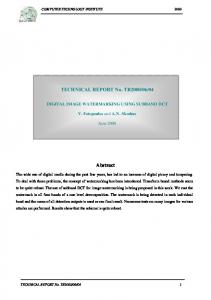
The operation of retaining the low-frequency coefficients of a DCT sub-frame and taking the half-size IDCT is, in effect, to perform anti-aliasing filtering and then followed by downsampling on the sub-frame in the pixel domain. This results in a downscaled version of the sub-frame. In the following, we shall analyze the performances and complexities of various downscaling filters for the 1-D case. The same analyses apply to the 2-D case since separable 2-D DCT is used in the decimation. For N samples of 1-D signal x, when downscaled by a factor of two, the downscaled N/2-sample signal y is obtained as follows. y = TNt / 2 P( N / 2)× N TN x (9) The downscaling filter is defined as M N / 2×N = TNt / 2 PN / 2×N TN (10) Using the downscaling filter, the input signal is linearly transformed with matrix M(N/2)×N to obtain a corresponding down-sampled output signal. The linear transform can be represented as an N-band filter bank structure shown in Fig. 2, where each filter hi is the reverse order of the ith row of the matrix M(N/2)×N. Hence, the z-transform of the output y can be obtained by Y ( z) =
1 N
N −1
∑ X (W
−k
k =0
z ) Fk (W − k z )
(11)
where W=exp(j2π/N), j = −1 and Fk ( z ) = x[n]
N / 2−1
∑z i =0
−2i
H i ( z )W
.
↑N/2
h2
↓N
↑N/2
z-1
h3
↓N
↑N/2
z-2
↑N/2
(12) y[n]
↓N
↓N
F0
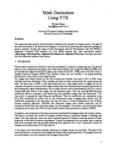
10 0 -10 -20 -30 -40 -50 -60 N=288 N=72 N=16 N=8 Bilinear 7-tap
-70 -80 -90 -100
0
0.1
0.2
0.3 0.4 0.5 0.6 0.7 Frequency in ×π rad/sample
0.8
0.9
1
Fig. 3. Comparison of magnitude responses of DCT-domain and pixel-domain decimation filters.
Table I Average computational complexity per block for each downscaling scheme Avg. Avg. additions Sub-frame multiplications per block Bˆk ,l size, N×M per block Bˆ k ,l
−2 ki
h1
hN
in [6] achieves the lowest complexity whereas the other larger sub-frame sizes lead to higher complexities. However, the visual quality of the scheme with a larger sub-frame size is better than that with a smaller sub-frame size as will be compared later.
Magnitude in dB
3. ANALYSES OF DCT-DECIMATION DOWNSCALING FILTERS
z-(N-1)
Fig. 2. The filter bank structure represents the downscaling operation. Fig. 3 shows the magnitude responses of the two pixel-domain filters: the bilinear filter and the 7-tap filter (as suggested in [2]), and the generalized DCT decimation filters with N = 8, 16, 72, and 288, respectively. As N increases, the gain of DCT decimation filters, |F0(z)|, becomes much flatter in the lowfrequency part (0~π/2), whereas the gain decreases rapidly in the high-frequency part (π/2~π). For the bilinear filter, the gain in the high-frequency part is always larger than its counterparts of DCT decimation filter and 7-tap filter. The smaller gain in the high-frequency part implies less visible aliasing artifacts in the downscaled image. Although increasing the sub-frame size for the DCT decimation filters will lead to better quality of downscaled image, it will also increase the computational complexity significantly. The computational complexities of the proposed DCT-decimation scheme with various sub-frame sizes are listed in Table I. From the table, the 8×8 sub-frame size used
352×288 176×144 88×72 44×36 16×16 8×8 [6]
227,840 63,232 18,944 6,304 1,792 1,024
224,640 61,600 18,096 5,848 1,568 768
4. EXPERIMENTAL RESULTS We evaluate the performances of DCT decimation with six different sub-frame sizes. Two 150-frame CIF (352×288) test sequences are encoded by an MPEG-2 encoder at 4 Mbps and 30 fps with the (15,3) GOP structure. The DCT-domain spatial downscaling transcoder performs the proposed downscaling scheme on an incoming coded video, and produces a spatially downscaled video of the QCIF size (176×144) coded at 1 Mbps. For comparing the performances of these schemes, the downscaled bitstreams are decoded and up-scaled to its original size, and then compute the average PSNR with its pre-encoded video. The up-scaling method is, similar to that proposed in [6], the reverse procedure of the DCT decimation schemes as summarized below: 1) Divide each downscaled video frame into sub-frames of (N/2)×(M/2) pixels. Then transform each pixel-domain subframe to a DCT sub-frame by (N/2)×(M/2) 2-D DCT. 2) Expand the size of each DCT sub-frame by a factor of two in height and width (i.e., N×M) with stuffing of zero coefficients in the high-frequency bands expended. 3) Use N×M IDCT to transform each expanded DCT sub-frame into pixel-domain sub-frame of N×M pixels.
FOREMAN(Y), 1Mbps
33
352x288 88x72 16x16 8x8 [6]
32.5
32 PSNR (dB)
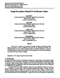
Fig. 4 shows the average PSNR comparison of the DCT decimation scheme with six different sub-frame sizes and the pixel-domain downscaling schemes. Fig. 5 shows the frame-byframe PSNR performance comparison. The larger the sub-frame size, the better the visual quality. The average PSNR performance improvement can be up to 0.9 dB for Container and 0.4 dB for Foreman. However, the performance improvement comes with an increased computational complexity. The DCT decimation schemes significantly outperform the pixel-domain downscaling filtering (the bilinear filter and the 7-tap filter) schemes in terms of average PSNR by up to 1.7~2.8 dB and 3~3.5 dB, respectively, for the two test sequences.
31.5
31
30.5
CONTAINER 28.5
30
Avg. PSNR (dB)
28 27.5
10
20
30
40
50
60
70 80 90 100 110 120 130 140 150 Frame No.
(b) Fig. 5. Frame-by-frame PSNR performance comparison of the proposed approach with six sub-frame sizes for (a) Container and (b) Foreman.
27 26.5 26 25.5 25
5. CONCLUSION ne ar Bi li
7ta p
[6 ] 8x 8
16 x1 6
44 x3 6
88 x7 2
17 6x 14 4
35 2x 28 8
24.5
(a) FOREMAN 31.5 31 Avg. PSNR (dB)
0
30.5 30 29.5 29
We proposed a generalized DCT decimation scheme which can adopt sub-frame sizes large than the traditional 8×8 block size. We analyzed the anti-aliasing filtering performance of the proposed scheme and the bilinear and 7-tap filtering schemes. We have also implemented a DCT-domain spatial downscaling transcoder based on the proposed scheme. Experiments show that the proposed scheme with a sub-frame size larger than 8×8 can achieve better visual quality, while leading to an increased computational cost. The PSNR performance improvement of using a large sub-frame size can be up to 0.9 dB on average.
28.5
REFERENCES
ne ar Bi li
7ta p
[6 ] 8x 8
16 x1 6
44 x3 6
88 x7 2
17 6x 14 4
35 2x 28 8
28
(b) Fig. 4. Average PSNR performance comparison of the proposed approach with six sub-frame sizes for (a) Container and (b) Foreman. CONTAINER(Y), 1Mbps
29
352x288 88x72 16x16 8x8 [6]
28.8 28.6
PSNR (dB)
28.4 28.2 28 27.8 27.6 27.4 27.2 27
10
20
30
40
50
60
70 80 90 100 110 120 130 140 150 Frame No.
(a)
[1] J. Xin, C.-W. Lin, and M.-T. Sun, “Digital video transcoding,” Proc. IEEE, vol. 93, no. 1, pp. 84-97, Jan. 2005. [2] T. Shanableh and M. Ghanbari, “Heterogeneous video transcoding to lower spatio-temporal resolutions and different encoding formats,” IEEE Trans. on Multimedia , vol. 2, no. 2, pp. 101-110, Jun. 2000. [3] P. A. A. Assuncao and M. Ghanbari, “A frequency-domain video transcoder for dynamic bit-rate reduction of MPEG-2 bit streams,” IEEETrans.CircuitsSyst.VideoTechnol ., vol. 8, no. 8, pp. 953-967, Dec. 1998. [4] S. F. Chang and D. G. Messerschmitt, “Manipulation and compositing of MC-DCT compressed video,” IEEE J. Select.AreasCommun. , vol. 13, no. 1, pp. 1-11, Jan. 1995. [5] W. Zhu, K. Yang, and M. Beacken, “CIF-to-QCIF video bitstream down-conversion in the DCT domain,” Bell Labs technicaljournal vol. 3, no. 3, pp. 21-29, Jul.-Sep. 1998. [6] R. Dugad and N. Ahuja, “A fast scheme for image size change in the compressed domain,” IEEE Trans. Circuit Syst.VideoTechnol ., vol. 11, no. 4, pp. 461-474, Apr. 2001. [7] Y.-R. Lee, C.-W. Lin, and Y.-W. Chen, “Computation reduction in cascaded DCT-domain video downscaling transcoder,” in Proc. IEEE ISCAS , vol. 2, pp. 860-863, May 2003.