Decision Tree Modelling: A Computer-Based Workbench Philip M. Sargent Cambridge University Engineering Dept., CAMBRIDGE CB2 1PZ, U.K.
Abstract This paper describes an implementation of a software workbench for manipulating decision trees. A new modelling facility has been added to the traditional decision tree. It is possible to set values of parameters at individual decisions or chance events which propagate down the tree to the terminal nodes. At the terminals, software models run (using the parameters as input) and the value produced by each model is propagated back up the tree using conventional foldback algorithms. In addition, explicit support is given for nodes (decisions or events) which are effectively the same but occur more than once in the tree - thus removing a common tedious difficulty in updating decision tree programs. Although many of the facilities are merely the same as traditional decision trees, the speed of response makes a qualitative difference in the way such trees are used. The workbench uses current user-interface technology to allow decision trees to be drawn on screen using a mouse. Pop-up windows appear when the mouse is "clicked" on individual parts of the tree and these are used to set the probabilities of chance events, the costs of decisions and any number of parameters for the evaluation models. Overall control of the foldback algorithms (e.g. estimated monetary value, minimum regret etc.) are set using a pull-down menu and can be changed at any time. Keywords decision, tree, software, workbench, model, decision support, user interface, graphical interface.
Introduction This work was begun at Analysys Ltd, the Cambridge telecommunications consultancy company, as an internal development project (Sargent 1987). The aim was to produce a workbench for use within the company to support any decision analysis that may be required in work for the company's clients. Although a particular project was in mind throughout the development, the requirement to support as yet undefined projects and the experimental nature of consultancy work implied that flexibility in the construction and editing of decision trees was paramount. 1 2 3
1.
This paper is in three parts: A brief review of decision trees and their use in practice A functional specification describing the types of facility which are desirable in a graphically-based decision analysis workbench A guide describing how the current implementation of the workbench functions. Incorporated in the description are plans for improving the modelling tool based on what has been learned from using it.
Decision trees
Decision trees are an aid to the individual in analysing a set of problems, and an aid to a group in communicating individual attitudes to a problem area. There are several possible reasons for introducing a software-based workbench: to speed up the application of an established methodology, thus encouraging o more experimentation and more focus on an exploration of ends which is less encumbered by the means of analysis, to improve the management of problems by making complex algorithms o available "painlessly" without placing too much power in the hands of those who know the method as opposed to those who know the problem, to manage the manipulation of one or several software models for sensitivity o analysis in a less programmer-oriented fashion than is currently possible Decision trees are most commonly used to find the most effective way of achieving a given end by manipulating the means, though in fact their greatest use is in structuring a problem area so that a decision maker can focus on only the important aspects of the problem (rather than being used to produce 'a solution') (Watson and Buede 1987). Indeed, one definition of a decision model is that it gives a satisfactory representation of the users' perceptions in a way which gives sufficient insight to enable the user to make a decision (Phillips 1982, Phillips 1984). 1 .1 . Major Concepts
A decision tree is a simple tree made up two sorts of actions: those where the outcome can be forced and those where the probabilities of the outcomes can only be
2
estimated. In this work these are termed "Decisions" and "Events" and are represented by nodes of the tree, as squares and circles respectively. Each action can lead to any number of outcomes, i.e. lead to several other actions. (The collection of outcomes from any action is termed here a collection of "Links") In real life only one of these Links is assumed to be possible from any one action. Eventually some terminal outcome is reached, represented on the tree as a triangle-shaped node. The user has to estimate some kind of "value" to be associated with each terminal outcome. The probability of each chance Event must be capable of being set by the user, and each determined action (Decision) should be capable of having a cost associated with it. This latter point is a slight extension to the standard decision tree treatment. 1.2. Value Propagation and Decision Criteria
The object of decision analysis is, in practice, merely to understand the problem better. In order to see how the various different final outcomes, and the probabilities of the Events interact, it is necessary to propagate the final set of values back through the decision tree according to some algorithm (commonly called a "criterion" in the literature). Several algorithms are used depending of the kind of problem (and the personalities of the decision makers). The basic algorithm is that of Estimated Monetary Value (EMV) where values at Event nodes are weighted linearly by the probabilities of the events leading to them. At Decision nodes the highest value is selected for propagation (i.e. the decision maker always makes the most profitable decision). The MaxiMin and MaxiMax algorithms throw away some probability information in the system compared with the EMV algorithm, at Decision nodes the algorithms are identical to EMV. At Event nodes the MaxiMin method just propagates the value of the least valuable outcome and the MaxiMax method propagates the value of the most valuable outcome. The Minimum Regret algorithm is a little more complicated to describe but easily programmed (Moore and Thomas 1976). It is desirable that the criterion can be changed (and changed back) very easily and without having to make any other change to the tree. 2.
Decision tree workbenches
Recent reviews of software aids for analysing decision problems by Buede ((1988, 1991)) have identified decision tree packages as being the most versatile since, as a class, they can also be used to analyse some multi-attribute utility and probabilistic nested-events problems.
3
We would expect the following characteristics from an ideal software tool for exploring the behaviour of decision trees: 1 That it would be graphically based, and that any part of the tree could be changed or interrogated just by pointing to it, 2 That subtrees could be copied, moved, deleted, attached and detached easily, 3 That some copies of subtrees would continue to reflect changes made to their original, but that others would maintain their individuality (the distinction being easy to see and to change), 4 That new Decision nodes and Event nodes could be created and attached easily, and 5 That the probabilities of the Event outcomes could be changed at any time. Then there are the standard facilities which are now taken for granted: that any unusual action by the user produces a helpful message, that work in progress can be saved, and reloaded, and of course that proper documentation is available,that the program does not give wrong answers and does not crash the computer. Extra facilities which would be necessary are: The ability to add a 'cost' to any decision so that if that route is taken, the 1 expected monetary value (EMV) is decreased by that amount. The facility to change the criterion (algorithm) for calculating the values, from 2 EMV to MiniMax, MaxiMin or Minimum Regret; without making any other changes. That the terminal nodes of the tree could be software models which calculate 3 the expected value rather than just a simple number. This last point is worth some extra study. The models might be all the same, or if they were different then some means would be required to select the appropriate model and to pass to it the parameters it needs. The particular parameter values should somehow reflect the path of events and decisions that lead to the particular terminal node where the model resides, and should be automatically kept in step with any editing of the tree itself. A description of such a system is given in this paper. It significantly enhances the usefulness of decision trees as a familiar and easy-to-use front end to a set of related software models. 2.1. Models
The workbench has one very significant extension to a standard decision analysis treatment and that it its inclusion of parametized models. Instead of relying on the user to estimate the value that will accrue from each and every final outcome, it is possible to set up a model (or models) at the terminals of the decision tree. These models can in principle be arbitrarily complex and are selected and driven by parameters which are attached to the tree at the Decisions or Events which determine them. If parameters are set to vary of a range of values then the decision tree is a way of incorporating and making sense of a large number of different schemata and variants of runs of a particular model and for performing sensitivity analyses.
4
2.2. Parameter Passing
Once the concept of a model has been introduced, it is clear that in most decision trees there will only be one model, and that the chance outcomes and the decisions made will all slightly affect the result (value) that the model produces by setting appropriate parameters. Each Decision and Event can change or add some parameter to a parameter list that propagates down the decision tree from the root. The values from the models then propagate back up towards the root according to the decision criterion (algorithm). In this way very large and complex decision trees can be made manageable and useful. An extra facility would be the ability to put a model at any position in the network. This would permit a decision tree based on a single year's events to be extended to subsequent years and yet still include all the year-end payoffs. 2.3. Comparison with other decision tree software
The package described here is best compared with decision tree packages SMLTREE, SUPERTREE, STRATATREE, DAVID and ARBORIST (Buede 1988). This review excludes packages which have either limited user interfaces or which have to be run from within another package. ARBORIST has a menu/text interface and is not a graphically-based system but
does permit easy copying of sub-trees, although other functions are cumbersome. Functions can be defined for costs and probabilities, but models for the terminal nodes, risk preference and all sensitivity analyses are handled by a separate spreadsheet interface. Probability distributions can be handled. DAVID is a free-format graphical Macintosh program for processing influence
diagrams according to the methods of Shachter (1986). The procedures for constructing the diagram and for setting probabilities on chance event nodes are very similar to those of the workbench described in this paper. DAVID supports logical dependence of probability relationships, value of information analysis and sensitivity testing with respect to a user-controlled risk tolerance function. Functions can also be defined for costs. The manipulation of sub-trees is not easy, editing is cumbersome and no models can be attached. (DAVID is not now maintained or kept up to date with recent versions of the Macintosh operating system.) SMLTREE supports a variety of sensitivity and risk analyses including Markov
processes. Functions, tables and probability distributions of values can be defined and Bayesian revision can be used when re-ordering events. Its user-interface is a menu system (or command language that must be learned) with line graph output. Sub-tree manipulation is performed by renaming.
5
STRATATREE is a restricted package for educational use using menu input and
keyboard cursor movement over the tree. Sub-tree editing is very easy using cut and paste operations. SUPERTREE's strength is the complexity of the models that can be linked to the
terminal nodes by external interfaces to spreadsheets. Bayesian revision for reordering, value of information analysis and many types of sensitivity analyses (but not useful probabilistic sensitivities) are possible. Risk preferences can be modelled. Input is by menus and editing of the tree is performed by commands. The workbench described in this paper most strongly resembles DAVID in appearance and STRATATREE in function since it does not support sensitivity analyses, risk tolerance, Bayesian revision or the value of perfect information. The workbench is unique in its handling of arbitrarily definable parameters which are passed to the models at the terminals and in its user selectable foldback functions. 3.
Workbench description
This section describes the basic list of functions that the user should see and be able to use on the workbench. Figures 1 to 9 display some of the sequences of actions that occur on creating a new tree using the workbench and editing parameter values. These figures will be used to justify the design decisions that were necessary to fulfil the objectives set out in the previous section. There are five separate actions that might result from clicking and un-clicking (selecting) any object on the workbench: editing the label, editing the cost/probability, editing the parameter list, selecting it prior to copying it, or starting/finishing a Link between nodes. 3.1. Creating Decisions, Events & Models
The three different tree objects: Decisions, Events and Models can be created by clicking on a "source" graphic box (Figure 1). A subsequent mouse click deposits a new object of the selected type on the workbench at the pointer position. Every newly-created object is pre-assigned with defaults to all necessary parameters, including a label. Linking Items and Tree Formation
Clicking on a Decision or Event object, followed by clicking on another Decision, Event or Model object will create a Link between them with default settings. (NB. The right mouse button is used for this.) When a new Link is added to an object in this way, the same Link is not added to any copies which may exist. Since the copies are no longer identical, the hidden background parameter-copying connection between the object with the new link and any existing copies is broken (see below).
6
It is possible to embed models at any point in the tree, not just at the terminal nodes (see below for the implications during tree Evaluation). Moving. Copying and Deleting Clicking on an existing object, holding the button down and dragging it to another position on the workbench will move it and all the sub-tree that depends on it to the new position. The original object and sub-tree is deleted, and a new sub-tree is drawn with all the links intact. Clicking on an existing object, holding the button down and dragging it to the Bin box will delete it and all the sub-tree that leads from it. Clicking on an existing object and re-clicking elsewhere on the workbench will create a copy of the object and its dependent sub-tree, complete with all settings and parameter lists (Figure 2). Any changes which are then made to settings or parameters in one copy are then reflected in all other copies. This change "mirroring" is broken when a new Link is made to the copy (see above), and so can be broken intentionally by making and then deleting a Link. There is a display option which shows the same key number against copies of the same object (the "copyKey"). Every newly created object is assigned a new, unique key number. 3.2. Evaluation and Algorithms
The ALGORITHM menu allows the user to specify the type of algorithm (criterion) used in evaluating the decision tree. The menu has four options which can be changed at any time: EMV (Estimated Monetary Value), MiniMax, MaxiMax and Mininum Regret (Figure 3). The process of calculating and displaying all the values is triggered by a simple mouse button press on the EVALUATE menu item. For speed, the tree is not re-drawn during evaluation, but previous calculated values are overwritten. There is also a menu option REFRESH to re-display the tree without calculated values or Labels. 3.3. Setting Costs, Probabilities, Parameters and Labels
The editing is in one of two modes: SETTINGS or PARAMETERS (Figure 2), SETTINGS refers to costs or probabilities whereas the latter mode is for defining and ascribing parameters which will affect the model values. All these numbers and text strings are assigned to the nodes and links on the workbench by clicking on them. In each case this brings up a Windows dialog box into which the appropriate information is typed. The existing information is presented in the dialog and may be edited or retyped or in the case of newly created objects the default information appears (Figures 4 to 7).
7
Costs and Probabilities Settings When an Link line leading from a Decision or Event object is selected by clicking on some point of the line, the dialog box which appears has the appropriate title and prompt text asking for a cost or a probability as appropriate. If instead of clicking on an Link line the mouse is positioned on the Decision of Event symbol itself then the first Link created from that object is selected. Parameters and Sets of Parameters
Editing parameters is not so simple as editing labels, costs or probabilities because each Link is associated with a collection of parameters. Thus a parameter must be selected (or created) first (Figures 5 and 6), and then its value edited (Figure 7). Every Link is supplied by default with an empty parameter list. Any number of parameters may be added and their names may be quite different between different Links. Parameters need not be numeric but can be strings. (In principle they can be complex, structured objects. The limitation on their complexity is whether the Models at the ends of the tree will have been programmed to interpret them). Setting & Editing Labels Labels may only be set for Decisions, Events and Models, not for Links. Labels are copied whenever an object is copied but editing a label does not change the labels on existing copies (irrespective of whether they are indpendent copies or are mirroring another object). The Label menu sets whether the labels or the copyKey numbers are displayed next to the objects on the workbench; copyKeys are always identical between mirrored copies whereas labels need not be. Currently only numeric labels are implemented in the prototype. 3.4. Multiple Trees and Windows
The workbench is not limited to studying one tree at a time but even this prototype is able to represent several at a time (and to copy and move items between them). It is currently necessary to save the workbench in its entirety from one invocation of the program to the next. It is very desirable that several different decision trees from the same workbench should be capable of being saved independently and that independently stored trees also be capable of being reintegrated. The simplest way of achieving this would be to run more than one workbench window at the same time. This is currently possible but copying subtrees between windows is not yet programmed.
8
3.5. Report Generation
It is necessary to be able to generate a text report on any decision tree so that it can be incorporated and edited into word-processor documents. It is also desirable that the workbench can be exported as a diagram to other word-processing or imageprocessing software. It is perhaps surprising that despite the large number of commercial decision analysis software packages, there is as yet no defined format for transferring data between them (Sargent 1991c). The rudimentary report format described here could form the core of a standard exchange syntax. Diagram Export is currently only possible through standard Windows facilities for capturing screen-dumps as bit-mapped images. In the prototype only a simple text file is produced, below is an example of this (slightly edited). (In the prototype implementation this is created from within the Actor programming environment and not by a menu item.) Note that every node object, a Decision, an Event or a Model, has associated with it a position in x and y coordinates on the workbench, e.g. Model[1] is at x=550, y=50. This is so that trees re-loaded from disc retain whatever layout the user previously set. In Table 1 the first three sections list the Models, Decisions and Events together with the Links associated with the latter two. Links from Events are labelled with probabilities, e.g. 0.33, and all the links from an Event add up to 1. Links from the Decisions are each labelled with a list of parameter names and their values. Every Link points to a unique node number which represents a Model, Decision or Event. Models in this example have no Links, but otherwise there is no restriction on the ordering and number of Decision and Event nodes.
9
The Models
The Structured Mapping
Model:[1] 550950: ->1 Model:[2] 551071: ->1 Model:[3] 552099: ->1 Model:[22] 252@264: ->1
Decision:[30] 1149290: Event:[31) 1890263: Decision:[32] 2259245: Event:[33] 2770222: Decision:[34] 3240200: Event:PS] 381@172: Decision:[13] 4320143: Decision:[10] 4810103: Event:[7] 513@83: Model:[1] 550050: Model:[2] 551071: Model:[3] 552099: Event:[7] 5100153: Model:[1] 5490130: Model:[2] 5490158: Model:[3] 5490187: Decision:[10] 4769268: Event:[7] 508@248: Model:[1] 5430220: Model:[2] 547@253: Model:[3] 5490274: Event:[7] 5020308: Model:[1] 5400295: Model:[2] 5420319: Model:[3] 5410349: Model:[22] 4060186: Model:[22] 3380215: Model:[22] 3050231: Model:[22] 2520264: Model:[22] 2180275:
The Probabilistic Events Event:[7] 513083: Links{0.33#->[1] 0.33#->[2] 0.33#->[3] Event:[31] 1890263: Links(0.5#->[32] 0.5#->[22] ) Event:(33] 277@222: Links(0.8#->[34] 0.2#->[22] Event:[35] 3819172: Links{0.3#->[13] 0.7#->[22]
The Decisions Decision:[10] 4810103: Links(0.#(central:0. )->[7] 0.#(central:2. )->[7] Decision:[13] 4320143: Links(3.#(timing:-3. )->[10] 1.#(timing:0. )->(10] ) Decision:[34] 3240200: Links(1.#->[35] 0.#->[22] ) Decision:[30] 1140290: Links{20#(politics:2. )->[31]
Model:[22) 139@311:
20#(politics:0. )->[22] ) Decision:(32] 2250245: Links{0.#(collab:3. )->[33] 0.#(collab:0. )->[22)
Table
1:
Listing of a decision tree
The "structured mapping" describes exactly the topology of the tree through the use of indentation. The Links from Decision: Links from Decision:
[13]
[10
have a parameter
have "timing" set and Links from
"central"
Decision: [34]
set,
have no
parameters set but will pass along those defined earlier in the tree. 3 . 6 . Software and programming
The package is written in Actor, a class/instance single-inheritance language which implements Smalltalk-like functionality using a C/Pascal-like syntax and building the user-interface on Microsoft Windows. It is a 'pure' object oriented language and as such much easier to learn than existing algol-style languages which have had object-oriented extensions added to them, such as C++ or Turbo Pascal. Particularly important to the ease of programming is the automatic memory garbagecollection that is standard with Actor, Smalltalk, and Eiffel (Meyer 1988). Experience
10
with this workbench demonstrates that Actor is ideal for this kind of programming where the flexibility of the prototype in the hands of a user is paramount. The are a number of inadequacies in the style in which the interface to the decision tree package is currently constructed (referred to above). Rectifying these will add little to the functionality of the package, but would be vital if this type of software were developed for commercial sale. Perhaps the most obvious redesign required is that the conversation is currently "modal", that is the type of action is selected before the object which is going to be acted upon and that the same actions by the user always have the same effect, i.e. they do not depend on which "mode" the workbench is in. It is known that the selecting an object before the action is more intuitive and leads to fewer mistakes, and is enshrined in the Apple Macintosh and Microsoft Windows style guides. In addition to style, there are some inadequacies of function due to the incompleteness of the prototype. The facility to store, re-load and merge previously constructed trees is 1 lacking, the main window cannot be scrolled, 2 only the EMV algorithm is implemented, 3 the facility to label the Decision and Event nodes with a short piece of text is 4 lacking. These relate to the conventional use expected from a simple decision tree workbench. The innovative aspect of using a decision tree to control software models is also currently limited. Only one model is available: a simple sum of all the parameters passed to it (but, unusually, it does not have to know the names of the parameters in advance and new parameters can be created by the user at any time). Specifications for defining sensitivity analyses with respect to user-definable parameters would be the most urgent new requirement. If the modelling facility were to be used more seriously then it would be necessary to build links to the operating system so that the tree could be used to control programs written by third parties, and to recover the results back again. The obvious link would be to use Microsoft's "Dynamic Data Exchange" (DDE) facility within MS Windows to link to spreadsheets written in Excel (or to C, Pascal or Fortran programs). There are similar facilities for Macintosh and Unix systems but Actor is not as yet available for these platforms. The current prototype is incomplete but it is already clear that greater attention to the style of interaction would be rewarded. Using pop-up dialog-boxes for every individual input from the user is tedious, and a need for a more "direct manipulation" feel is clear. (Though this is less of a problem with faster computer hardware.)
11
Nevertheless the rate at which complex decision tree models can be constructed and exercised is startling. 4.
Conclusions
This prototype decision tree workbench has fulfilled its original purpose of proving the ideas of using decision trees to control parametised models and of exploring the increased ease of use possible with modern graphical user interfaces. Even in its current incomplete state it is a useful "sketchpad" for rapidly exploring new decision trees with modest numbers of nodes. Experience with this prototype has indicated several aspects which could be improved or changed. Although the software is completely general in application, our research is focused on the use of decision trees in managing technical aspects of engineering design projects and we will be specifically exploring the tool's use in planning the accession of materials property information (Sargent 1991a, Sargent 1991b). Acknowledgements
Most of the work described here was done while the author was an employee of Analysys Ltd., Cambridge, and the author wishes to thank David Cleevely and Geoff Walsham for the initial impetus to attempt work in this area, and David for providing the facilities. Thanks also to Janet Efstathiou who was also beginning to program in Actor at the time this work was begun and who provided help and encouragement. "Actor" is a trademark of the Whitewater Group, "MS-DOS", "DDE", "Excel" and "Windows" are trademarks of Microsoft Corp., "Turbo Pascal" is a trademark of Borland Intl., "Macintosh" is a trademark of Apple Corp. SUPERTREE is sold by Applied Decision Analysis, Menlo Park, SMLTREE by James Hollenberg, New York, STRATATREE by Decision Support Software, McLean, Virginia, DAVID by Duke University, North Carolina and ARBORIST by Data Systems Group, Texas Instruments Inc., Atlanta.
12
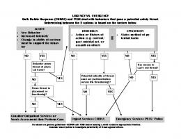
Figure Captions 1 HELP menu item highlighted, a single tree is shown with numbered nodes. Note that two Model nodes are both labelled "1" and four are labelled "27". Nodes with the same numeric label have identical behaviour. Note the four boxes in the upper left, these are the "tear-off" pads for creating new Events, Decisions and Models. 2 EDIT menu item highlighted showing that the workbench is in topology editing mode. The subtree headed by Decision node 31 has been duplicated. 3 ALGORITHM menu item highlighted showing the EMV algorithm selected. The tree is now shown with values at each node. Note that the "27" and "1" Model nodes show the same value, 161 and 25 respectively. (No parameters are set in the tree yet so only the default value of each model determines its value.) The colouring of the nodes allows the preferred route to be followed: start at the root and follow the coloured nodes. The Link between Decision node 31 and Model 1 is selected and a dialog box 4 appears asking which parameter on that Link the user wishes to edit. No parameter currently exists so "nil" is shown. Immediately following from Figure 4, the user has typed "a" as the name of 5 the parameter to edit. Following Figure 5, a new dialog box appears asking for the value for 6 parameter "a". Following Figure 6, the user gives a value of 1999 to parameter "a". 7 The tree is evaluated by clicking on the EVALUATE menu item. (Exactly the 8 same sequence of parameter setting has done for the Link between the Decision node 47 and the upper Model 1 as between node 31 and Model 1.) Note that all subtrees are evaluated even if they share no common root. All Model is now give the same value again, 1999, but for different reasons: the two identical subtrees because they are constrained copies, the upper Model 1 because it was individually set. The REFRESH menu item was selected to clear away the values, and the 9 workbench is being closed down by selecting CLOSE.
printed Thursday, February 13, 1992
13
References BUEDE, D. M. 1988. Decision Software: State-of-the-Art Review. QED Information Sciences Inc. (unpublished report). September 1988. BUEDE, D. M. 1991. Superior design features of decision analytic software. Comp. Opns. Res. MEYER, B. 1988. Object-Oriented Software Construction. Prentice Hall, Paris, France. MOORE, P. G. and H. THOMAS 1976. The Anatomy of Decisions. Penguin Books, PHILLIPS, L. D. 1982. Requisite Decision Modelling, A Case Study. J. Opl. Res. Soc 33, 303-311. PHILLIPS, L. D. 1984. A Theory of Requisite Decision Models. Acta Psych. 56, 29-48. SARGENT, P. M. 1987. Development of a Workbench for Decision Analysis Modelling, Interim Manual 1.0. Analysys Ltd., Cambridge Report. 87357, 23 Dec.1987. SARGENT, P. M. 1991a. Decision Techniques for Materials Selection. Cambridge University Engineering Department, Engineering Design Centre Technical Report. CUED/C-EDC/TR.4, August 1991. SARGENT, P. M. 1991b. Materials Information for CAD/CAM. ButterworthHeinemann, Oxford, UK. SARGENT, P. M. 1991c. Technical Data Interchange Using Tabular Formats. J. Chemical Information and Computer Sciences 31, 297-300. SHACHTER, R. D. 1986. Evaluating Influence Diagrams. Opns.Res. 34, 871882. WATSON, S. R. and D. M. BUEDE 1987. Decision Synthesis: The Principles and Practice of Decision Analysis. Cambridge University Press, Cambridge, UK.
14
Decision Analysis: The ANALYSYS nalyser File Algorithm Labels Edit Evaluate Refresh Clear HelD DAM BIN A 0 Analvsys Commands Algorithm Editing riling Hints
HELP menu item highlighted, a single tree is shown with numbered nodes. Note that two Model nodes are both labelled "1" and four are labelled "27". Nodes with the same numeric label have identical behaviour. Note the four boxes in the upper left, these are the "tear-off' pads for creating new Events, Decisions and Models.
1
File Algorithm Labels
0
2
A
BIN
Decision Analysis: The AHALVSYS Analyser Edit Evaluate Refresh Clear Helo Settings Parameters VT000loOto Label;
EDIT menu item highlighted showing that the workbench is in topology editing mode. The subtree headed by Decision node 31 has been duplicated.
Flle
0
Decision Analysis; The AHALYSYS Analyser Algorithm Labels Edit Evaluate Refresh Clear Selo Maxi/lax Max1flin Regret.
N
25 161
A 25
208
161
3
161
ALGORITHM menu item highlighted showing the EMV algorithm selected. The tree is now shown with values at each node. Note that the "27" and "1" Model nodes show the same value, 161 and 25 respectively. (No parameters are set in the tree yet so only the default value of each model determines its value.) The colouring of the nodes allows the preferred route to be followed: start at the root and follow the coloured nodes.
Decision Analysis; The AHALYSYS Analyser File Algorithm Labels Edit Evaluate Refresh Clear Selo
Decision Event Paraneter Editiny -) 1 Which parameter do you wish to edit 7 •
11321 Ok
(Cancel)
A 27
27
A 27
4
The Link between Decision node 31 and Model 1 is selected and a dialog box appears asking which parameter on that Link the user wishes to edit. No parameter currently exists so "nil" is shown.
File Algorithm Labels Edit Evaluate Refresh Clear Help
Decision Event Parameter Editing -> 1
Which parameter do you wish to edit
al
L.M4
(Cancel)
27
5
Immediately following from Figure 4, the user has typed "a" as the name of the parameter to edit.
Decision Analysis: The ANALYSYS Analyser File Algorithm Labels Edit Evaluate Refresh Clear Help
Decision Event Parameter Editing -> 1 Give a new value
Ok )
6
(Cancel)
Following Figure 5, a new dialog box appears asking for the value for parameter "a".
Decision Analysis: The AHALVSYS Analyser File Algorithm Labels Edit Evaluate Refresh Clear Help
Decision Event Parameter Editiny -> 1
27
27
27
7
Following Figure 6, the user gives a value of 1999 to parameter "a".
Decision Analysis: The ANALVSYS Analyser File Algorithm Labels Edit Evaluate Refresh Clear Help
1386
161
161
161
8
The tree is evaluated by clicking on the EVALUATE menu item. (Exactly the same sequence of parameter setting has done for the Link between the Decision node 47 and the upper Model 1 as between node 31 and Model 1.) Note that all subtrees are evaluated even if they share no common root. All Model I s now give the same value again, 1999, but for different reasons: the two identical subtrees because they are constrained copies, the upper Model 1 because it was individually set.
Decision Analysis: The ANALVSYS Analyser
9
ReJitort Move Size Minimize Maximize
A11.fF5 Alt+FB A1t49 A1t410
(Anse,
Alt+F4
s Edit Evaluate Refresh Clear Melo
The REFRESH menu item was selected to clear away the values, and the workbench is being closed down by selecting CLOSE.
File Edit Doit! Inspect! Browse! Cleanup! Not understood:eventTree Not understood:EventTree Not understood:EventTree 16 bytes used. 12370 bytes available.Erro Error:dosError
Show Room! Utility Templates Demos! Actor [ #UInag e].fileName: =asciiz("dan. ima")
- dam.imal-
load(-pfts4.1od-) load() DA: -new(Decidindow, nil,-DAmenu", "Y', nil) dump (U. event Tree)
compiling:command(DecUindo 844 bytes reclaimed. 12402 bytes available. ACTOR version 1.1A Copyright @ 1986, 1987 The Uhitewater Group, Inc. All rights reserved.
Decision Analysis; The ANALYSTS Analyser File Algorithm Labels Edit Evaluate Refresh Clear Nelo
0
BIN
DAN Analysis Commands Alsi)rithn Editinl Filion
:•.',.•.•••”•:••••••••••••
Cambridge University Engineering Department Dr. Philip Sargent MATERIALS GROUP Trumpington Street Cambridge CB2 1PZ tel. +44 (223) 245249332627 fax. +44 (223) 332662
[email protected] Prof.Dr.Dr.h.c.H.-J. Zimmerman Institut fiir Wirtschaftswissenschaften Lehrstuhl Unternehmensforschung RWTH Aachen Templergraben 64, 5100 Aachen
[email protected] Friday, May 21, 1993 Dear Prof. Zimmerman, I have just discovered a letter from you in my files (12 October 1992), which I believe I answered. However I can find no copy of my reply, so it may have been misfiled (or I may have e-mailed without success). I am very sorry. Yes, I did send you a paper Decision Tree modelling: a computerbased workbench. I am sorry I did not say which journal I intended to submit it to. If possible, could you consider it for the European Journal of Operations Research ? The format as I sent it to you should be correct as specified in the "instructions to authors". Do you still have the four copies ? It is probably in the category computer focus or short communication. The keywords (from the approved list) are computers and decision support systems. Sincerely,
P 11,561-.7 Philip Sargent enc. copy of your letter
1