{J.Thevenon, Jesus.Martinezdelrincon, R.Dieny, J.Nebel}@kingston.ac.uk .... extended in three manners: ight images may ..... Hartley, R.I., 1999. Theory and ...
DENSE PIXEL MATCHING BETWEEN UNRECTIFIED AND DISTORTED IMAGES USING DYNAMIC PROGRAMMING Jerome Thevenon, Jesus Martinez-del-Rincon, Romain Dieny and Jean-Christophe Nebel Digital Imaging Research Centre, Kingston University, Penhryn Road, Kingston-Upon-Thames, KT1 2EE, Surrey, UK {J.Thevenon, Jesus.Martinezdelrincon, R.Dieny, J.Nebel}@kingston.ac.uk
Keywords:
Stereo correspondence, dynamic programming, unrectified images, distorted images.
Abstract:
In this paper, a novel framework for dense pixel matching based on dynamic programming is introduced. Unlike most techniques proposed in the literature, our approach assumes neither known camera geometry nor the availability of rectified images. Under such conditions, the matching task cannot be reduced to finding correspondences between a pair of scanlines. We propose to extend existing dynamic programming methodologies to a larger dimensional space by using a 3D scoring matrix so that correspondences between a line and a whole image can be calculated. After assessing our framework on a standard evaluation dataset of rectified stereo images, experiments are conducted on unrectified and non-linearly distorted images. Results validate our new approach and reveal the versatility of our algorithm.
1
INTRODUCTION
Dense pixel matching is a low-level process which is involved in many computer vision applications including navigation, security, entertainment and video surveillance. Not only is it often an essential step in 3D reconstruction from a pair of stereo images, but it is also used in object detection and video tracking, especially when the camera is not fixed (Note, et al., 2006) (Yaguchi,, et al., 2009) as it is the case with camera phones (Yin, et al., 2007). Recent reviews describe and analyse the many algorithms which have been proposed to address this matching process (Scharstein & Szeliski, 2002) (Lazaros, et al., 2008). Most approaches performing dense pixel matching assume images have been rectified so that their task can be reduced to finding correspondences between a pair of scanlines. Among these techniques, those based on dynamic programming (DP) are of particular interest since they combine good accuracy with low computational complexity as demonstrated by a recent real-time FPGA hardware implementation (MacLean, et al., 2010). Their main drawback is that they require the knowledge to project images onto a common coordinate system. Although, in many applications those transformations can be estimated by either camera calibration or image rectification, calibration
is sometimes either impossible or impractical, whereas the computational cost of accurate rectification models prohibits their usage in realtime application. Moreover, none of these methods is suitable when a camera lens displays unexpected distortions, such as those generated by raindrops, weatherproof covers or dust. In this paper, we propose a novel DP-based dense pixel matching algorithm which can handle unrectified and non-linearly distorted images. After a state-of-the-art review, we detail our novel matching algorithm. Finally, it is validated with experiments conducted on unrectified images and images displaying significant deformations.
1.1
Related Work
Generally, pixel matching approaches (Barnard, et al., 1982) (Dhond, et al., 1989) (Brown, et al., 1992) (Jones, et al., 1997)(Scharstein & Szeliski, 2002) assume that images have been rectified so that the task is simplified to establishing correspondences between corresponding rows of the rectified images. The standard process for rectification is homography based, also called planar rectification, where image planes are transformed so that the corresponding space planes coincide (Ayache & Hansen, 1998) (Hartley, 1999). A major limitation of this class of
approaches is that, if epipoles are located in the images, planar rectification produces infinitely large images. This problem has now been solved under specific conditions by using either cylindrical (Roy, et al., 1997) or spherical rectifications (Pollefeys, et al., 1999)(Wan & Zhou, 2008). In addition to adding significant computational complexity, these methods still overlook issues such as sub pixel coordinates, infinite epipoles (Lim, et al., 2004) and the non preservation of conjugate epipolar polarities (Oram, 2001). An alternative to these approaches is to fully calibrate cameras to estimate the appropriate transformation between images. However, since this process is usually manual or relies on very specific environments, its usage has very strong limitations. In any case, all these methods depend on finding a set of accurate matching points, resampling images and appropriate lens distortion models, of all which affect the matching performance. Moreover, there are scenarios where these methods are totally inadequate. For example, visual tracking is seriously degraded by weather conditions when the presence of water drops produces undesirable temporal and localised distortions (Barnum, et al., 2007) (Garg & Nayar, 2004); similarly, vision systems on space exploration rovers are affected by dust accumulation (Willson, et al., 2005). Although performing dense pixel matching without prior image transformation is an attractive proposition, very few algorithms have been suggested. This problem was addressed using either multi-resolution image correlation (Duchaineau, et al., 2007)(Zhengping, 1988) or a genetic algorithm (Tippetts, et al., 2010). It was also suggested that a self-organizing neural network could potentially be used under these conditions (Vanetti, et al., 2009). Unfortunately, all these methods display high computational complexity and recursivity, which makes them unsuitable for real-time and hardware implementations. This review highlights the limitations of rectification and calibration procedures and shows that, currently, bypassing this step leads to solutions with high computation costs. In order to address this, a novel algorithm could be designed by extending one of the approaches developed to tackle in realtime the simpler task of scanline matching (Forstmann, et al., 2004) (Gong, et al., 2006) (Lu, et al., 2009) (Salmen, et al., 2009) (Wang, et al., 2006) (Yang, et al., 2006). Among them, techniques based on DP seem particularly suitable: although they are not the most accurate, performance analysis has shown they provide an excellent compromise between accuracy and speed (Cox, et al., 1996)
(MacLean, et al., 2010) (Scharstein & Szeliski, 2002) (Brown, et al., 2003) (Tappen & Freeman, 2003). Their low intrinsic computational complexity even led to a recent FPGA hardware implementation (MacLean, et al., 2010). In this paper, we propose a novel dense pixel matching algorithm based on the DP paradigm which can operate with unrectified images without camera calibration.
2
ALGORITHM
We propose a novel dynamic programming algorithm which is able to establish dense pixel correspondences between two unrectified and/or distorted images. Since our method is based on a DP approach, it relies on two main steps: the storage of local calculations and their reuse to produce a global solution. In this section, we first describe how a 3D scoring matrix is computed. Then, we propose a refinement of these calculations, i.e. introduction of the extended gap concept. Finally, we detail the backtracking phase which allows generating optimal global correspondences. It is important to note that, although the usage of 3D matrices within DP based pixel matching algorithms was proposed by Sun (Sun, 2002) (Sun-2, 2002), this was only a means of efficiently calculate the correlations over a sliding window. This did not address the requirement of image rectification and was only suitable for scanline matching.
2.1
3D Scoring Matrix
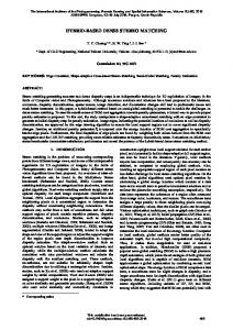
Similarly to many dynamic programming-based algorithms designed for scanline matching (Geiger, et al., 1992) (Belhumeur, 1996) (Cox, et al., 1996) (Torr & Criminisi, 2004), the first stage of our algorithm fills in a scoring matrix according to a given scoring scheme. However, our approach does not restrict itself to finding pixel correspondences between scanlines, but between a scanline and an entire image. The strength of this scheme is that images do not need to be rectified and matching can be achieved even when one of the images displays important distortions. Consequently, a scanline on the first image does not need to match a straight line, but may correspond to a curve in the second image (see Figure 1). Since this algorithm is an extension of an algorithm designed for matching stereo pairs of images (Authors, 1111), we use the same convention: the first and second images are referred as the left and right images.
a) b) Figure 1: Views of the same scene captured using different camera lenses. Green curves: groundtruth dtruth correspondence between 3 scanlines of image a) and pixels of image b).
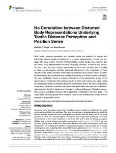
First, a 3D scoring matrix is generated for each scanline s of the left image. Assuming the left image scanlines have a length L and the dimensions of the right image are WxH (width x height), the size of the scoring matrix, sc,, is LxWxH. A matrix cell ci,j,k is defined by three coordinates, where i represents the elements of the scanline and j and k the column and line of the right image (see Figure 2).
next column (j+1)) in the same line (k), ( match m1, the line below (k+1), match m2, or the line above (k-1), ( match m3 (see Figure 3). Since a change of line and column means moving by a distance of √2 pixels in the image, this implicitly adds a virtual gap of �√2 � 1� pixels. Therefore, this type of match should be less rewarded than a match along the i+1,j+1,k direction. If matches between pixels cannot be found, a gap has to be introduced in either the image or the scanline. A gap in the image indicates that a scanline scanlin pixel does not have any correspondence in the image: this pixel is occluded in the right image. Consequently, the alignment is extended by moving to the next element in the scanline, i.e. ci+1,j,k (gap g4) (see Figure 4).
Figure 3: Matching. Matching
Figure2: 3D scoring matrix.
Matrix cells store the maximum value which can be achieved by extending a previous alignment. When a DP approach is used to find correspondences between two scanlines, an alignment can only be extended in three manners: pixels of the left and right images may have similar values, i.e. there is a match,, or one of the pixels may be occluded in either the first or the second sequence, i.e. a gap has to be introduced. Here, an alignment finishing in the cell, ci,j,k, can be extended in seven ways. Since a match means that a pixel of the scanline corresponds to a pixel in the image, the matching cell must be contiguous to the previous cell, ci,j,k. Moreover, dynamic programming approach requests moving forward in order to come to an end. Consequently, a match can occur in either cell ci+1,j+1,k, ci+1,j+1,k+1 or ci+1,j+1,k-1, which corresponds to a correspondence between the next pixel in the scanline (i+1), ), and respectively, the next pixel in the
Figure 4: Gap in the image. image
Alternatively, image pixels may be occluded in the left image. This implies not moving in the I direction, i.e. the displacement in the matrix is towards either ci,j+1,k (gap g1), ), ci,j+1,k+1 (gap g2) or ci,j+1,k-1 (gap g3) (see Figure 5). ). Similarly to the case of matching, a change of line implies adding an extra gap of �√2 � 1� pixels, which also needs to be penalised. As shown, each cell of the 3D scoring matrix can be accessed from 7 directions. During the filling process, for each of these directions the cell value is
calculated according to the cost of the move, i.e. match or gap costs: the highest value and the direction(s) it is coming from are stored in the cell. This information is used in the backtracking process.
Figure 5: Gap in the scanline.
In order to define the costs of these possible moves, we introduce 3 parameters: m is the reward for a perfect match, g is the penalty for a single gap, and Δ is the penalty for an imperfect match, which is set at the absolute value of the intensity difference between the scanline pixel, s(i), and the image pixel, Im(j,k). Δ |� � � �� �, ��| (1) Using these parameters, the cost of adding an extra gap of �√2 � 1� pixels, p, can be expressed by: � ��√2 � 1� � � ��� (2) Before starting the filling process, the matrix needs to be initialised. First, the initial alignment score is set to zero. This involves extending the initial matrix of dimensions LxWxH with the planes (0,J,K) and (I,0,K). Since the alignment can start from any line of the image, cells with coordinates i=0 and j=0 are filled with zeros. Then other cells from the planes (0,J,K) and (I,0,K) are initialised according to cumulated gap penalties. Finally, the scoring matrix, sc, is filled in according to the following pseudo-code: for i=1 to L for j=1 to W for k=1 to H Δ ← |s(i)-Im(j,k)| m1 ← sc(i-1,j-1,k)+m- Δ m2 ← sc(i-1,j-1,k+1)+m-Δ-p m3 ← sc(i-1,j-1,k-1)+m-Δ-p g1 ← sc(i,j-1,k)+m-g g2 ← sc(i,j-1,k+1)+m-g-p g3 ← sc(i,j-1,k-1)+m-g-p g4 ← sc(i-1,j,k)+m-g sc(i,j,k) ← max(m1,m2,m3,g1,g2,g3, g4) end for end for end for
As a consequence, the time complexity of the proposed algorithm is � ���� per scanline.
2.2
Extended Gap
In the initial scoring scheme, each individual gap has a fixed penalty. However, due to the nature of stereo images and successive video frames where different perspectives create partial object occlusions, occluded pixels tend to cluster instead of being equally distributed across an image. We propose to exploit this observation by introducing a lower penalty for new gaps which extend existing gaps. An affine gap penalty is used where the initial gap opening penalty is set at g and each extension of a gap increases the total penalty by a lower value, e, (e