Deployable Structures in the CubeSat Program MOVE M. Langer(1), C. Olthoff(1), L. Datashvili(2) , H. Baier(2) , N. Maghaldadze(2) , U. Walter(1) (1)
Institute of Astronautics, Technische Universität München Boltzmannstraße 15, 85748 Garching, Germany Email:
[email protected],
[email protected],
[email protected] (2)
Institute of Lightweight Structures, Technische Universität München Boltzmannstraße 15, 85748 Garching, Germany Email:
[email protected],
[email protected],
[email protected] ABSTRACT This paper investigates the utilization of deployable and expandable structures for communication purposes and solar power generation on CubeSats. We present the design and on-orbit results of the flight-proven solar-panel release mechanism of the first satellite of Technische Universität München First-MOVE, as well as the preliminary design of a solar panel deployment mechanism based on smart memory alloys for the second satellite MOVE II. Preliminary studies on a CFRS (carbon fibre reinforced silicone) shell membrane antenna as well as two other possible payloads for MOVE II are briefly described.
1.
INTRODUCTION
The CubeSat program MOVE (Munich Orbital Verification Experiment) was initiated in 2006 at the Institute of Astronautics (LRT) at the Technische Universität München (TUM) in Munich, Germany, with the objective of educating students and the validation of new technologies in space. After a successful launch of the programs’ first CubeSat FirstMOVE in late 2013, the second CubeSat MOVE II is currently under development. CubeSats, a class of satellites established in 1999 by CalPoly and Stanford University, are defined by the CubeSat Standard [1], which among other constraints, limits the satellites volumes to multiples of a so-called Unit, a 10x10x10 cm cube. Although for the designers of such systems this standardization has many advantages, the inherent volume constraint presents a challenge, e.g. for payloads that require large solar power generators, or for missions with high communication data rates requiring either parabolic antennas or a low-interference environment far away from the satellite’s main body. Deployable and expandable structures are a versatile option to overcome these restrictions and facilitate advanced payloads on CubeSats. Current and past CubeSat missions are based on self-developed [2] or commercial off-the-shelf (COTS) [3], [4] deployable and/or expandable structures for solar power generation. Most of the mechanisms used for solar panel deployment rely on conventional techniques like the utilization of melting wires and springs for hold down and release. For some missions more complex systems for gravity gradient stabilization [5], communication purposes [6] or a combination of communication and solar power generation [7] have been proposed or already flown. For the 1-Unit (1U) CubeSat First-MOVE a multi-purpose deployment mechanism for two solar panels, as well as the UHF and VHF antennas of the satellite were developed. The student-designed mechanism, based on two redundant melting wires and springs, deployed two extra “flap panels” for additional surface area to generate electrical power via solar cells. An iterative design process and the subsequent verification of the mechanism on the REXUS 4 (Rocket-borne Experiments for University Students) sounding rocket resulted in the successful deployment of both panels in space during the First-MOVE mission. Based on the experience from the first satellite, an advanced solar panel deployment mechanism for the 2-Unit CubeSat MOVE II, called SMARD (Shape Memory Alloy Reusable Deployment mechanism) is currently under development at LRT. Rather than melting wires the new mechanism will use destructive shape memory alloy technology, enabling repeated deployment tests with the flight units. This repeatability will allow the team to perform more tests in less time and will therefore enhance the reliability of the deployment mechanism and the confidence in the overall system. SMARD has been selected by DLR (Deutsches Zentrum für Luft- und Raumfahrt) for the REXUS 17/18 launch campaign in early 2015.
Proceedings of the 2nd International Conference "Advanced Lightweight Structures and Reflector Antennas", 1 – 3 October 2014, Sheraton Metechi Palace Hotel, Tbilisi, Georgia
Preliminary studies, started in 2013 and led by the Institute of Lightweight Structures (LLB) of TUM, highlighted the potential of expendable and deployable Carbon Fibre Reinforced Silicone (CFRS) structures for CubeSats. In particular the unfolding of a CFRS shell-membrane antenna reflector with parabolic shape and flexible Copper Indium Gallium Selenide (CIGS) solar cells on the back side was studied for C-Band or X-Band communication on CubeSats or small satellites. This paper is structured as follows: In Section 2 the multi-purpose deployment mechanism of First-MOVE as well as its on-orbit deployment are presented. Section 3 deals with the shape memory alloy reusable deploy mechanism currently in development at LRT for the second satellite mission MOVE II. The proposed deployable CFRS structures for MOVE II are briefly discussed in Section 4. 2.
FIRST-MOVE MULTI PURPOSE DEPLOYMENT MECHANISM (MPDM)
For First-MOVE, as for many other university satellites in the last decade, the CubeSat Standard from CalPoly [1] was chosen. Among others the geometrical requirements defined by this standard (see Fig. 1 for 1U) usually impose limits on power generation (i.e. the available surface area of the cube for solar cells) and communications (e.g. antenna length without deployment, usage of patch antennas). Since CubeSats use standardized commercially available launch adapters from various providers, there are no exceptions with regard to the geometric requirements. Deployable solar panels and/or deployable antennas can be used to overcome these constraints and enhance the capabilities of a CubeSat.
Fig. 1. Geometrical restrictions from the CubeSat Standard for 1 U [1]. Hence the design of First-MOVE includes two deployable solar panels, increasing the maximum power produced by 60%. For communication demands, half dipole antennas for UHF and VHF are attached to the upper and lower panel, respectively (see Fig. 2). To keep the panels in a locked position during launch and deploy them via a signal from the onboard data handling system (OBDH) of the satellite, a hold down and release mechanism (HDRM) was designed over several iterations [7]. Further requirements regarding acceleration, vibrations, temperature and shock were considered and resulted in a redundant melting wire concept with a rotational spring-articulated bracket (see Fig. 3).
Proceedings of the 2nd International Conference "Advanced Lightweight Structures and Reflector Antennas", 1 – 3 October 2014, Sheraton Metechi Palace Hotel, Tbilisi, Georgia
Fig. 2. First-MOVE in launch configuration (left) and deployed configuration (right). The HDRM functions as follows: After the successful deployment from the launch adapter, redundant deployment switches sense the deployment and the boot sequence of the OBDH is started. After a predetermined time (8 minutes) both HDRMs are actuated sequentially by a signal from the OBDH. The signal switches a MOSFET transistor to allow a current of ~800 mA at 3,3V to pass through redundant Constantan wires, again in a sequential fashion. The dissipative heat produced by the Constantan wires melts a Dyneema string that holds two spring-loaded brackets together. Subsequently the rotation spring articulates both brackets, freeing a half cone attached to the flap panel. This way the panel can move freely and is rotated by the so-called C-Springs (the C-Springs are highlighted in Fig. 3). Along with the flap panels the two antennas are deployed. During launch the antennas are curled up between the side panels and the satellites’ body.
Fig. 3. HDRM mechanism design (left) [8] and final HDRM with highlighted C-springs (right). Successful ground deployment tests were followed by vacuum chamber tests at LRT and vibration/acceleration tests at IABG GmbH in Ottobrunn, Germany. After each test the deployment of the panel was tested and the HDRM visually inspected. For verification purposes one HDRM was flown on the REXUS-4 mission. The sounding rocket hosted among others a verification experiment for critical pico-satellite components, called VERTICAL (Verification and Test of Initiation of CubeSats after Launch). Hosted inside the VERTICAL experiment, the HDRM showed nominal behaviour
Proceedings of the 2nd International Conference "Advanced Lightweight Structures and Reflector Antennas", 1 – 3 October 2014, Sheraton Metechi Palace Hotel, Tbilisi, Georgia
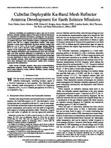
and released the panel 1.48 seconds after activation of the melting wire. Flap Panel maximum velocities of 1.66 m/s were observed, which are in good agreement with the data obtained during ground tests [8]. On a second sounding rocket mission in 2009 the HDRM was used operationally in the FOCUS experiment to deploy an experimental structure that cured under UV lighting [9]. First-MOVE was launched on the 21st of November 2013 with the Dnepr Cluster Mission from Yasny, Russian Federation. 937 seconds into the flight, the deployment from the ISIPOD deployer number 2 occurred as expected, placing the satellite into a low earth orbit at 97.79° inclination. 8 minutes after ejection from the ISIPOD, both panels were deployed. Along with the first data beacons received from the satellite, the successful deployment of both panels was proven. The communication link established on launch day can be taken as the first evidence of deployment at least of the lower panel with the downlink VHF antenna attached. Additionally, temperature sensor data retrieved via automatic data beacons (see Fig. 4) during the commissioning phase showed a temperature variation of the flap panel between 88.8°C and +13.5°C. According to thermal simulations, we interpret the data as a deployed upper panel (not facing the satellites’ body but outer space).
Fig. 4. Example of on-orbit data received from First-MOVE showing the satellites’ temperature during eclipse. Unfortunately it was not possible to retrieve data from the satellite after December 19 th 2013, presumably due to a malfunction in the OBDH system, which left the satellite in a mode where it is only transmitting CW beacons. Although the short mission duration seems somewhat discouraging, the overall MOVE program with more than 70 students involved and major in-house technology development and validation outweighs the fact that several secondary mission goals were not achieved. 3.
MOVE II SHAPE MEMORY ALLOY REUSABLE DEPLOYMENT MECHANISM
To follow up the educational and technological achievements of First-MOVE, MOVE II was initiated as the successive satellite project of LRT at the end of 2011. To enable the mission to include a scientific payload, the satellites’ size was doubled to 2U, allocating the bus in 1U and the scientific payload in the other unit. Furthermore, as the potential payload enhances the demand for computational and electrical power, the successful solar-panel deployment concept of FirstMOVE has been continued and the HDRM refined. Following the success of VERTICAL for verification of the first
Proceedings of the 2nd International Conference "Advanced Lightweight Structures and Reflector Antennas", 1 – 3 October 2014, Sheraton Metechi Palace Hotel, Tbilisi, Georgia
mechanism, a new student project called SMARD was initiated in late 2013 [10]. The goal of SMARD is to develop a solar panel hold down and release mechanism for a 2U CubeSat using shape memory alloys. As with the previous HDRM mechanism the validation will take place on a REXUS sounding rocket, scheduled for launch early 2015. Since the project is currently ongoing, only the preliminary design of SMARD will be described. The biggest incentive for a re-design of the flight-proven HDRM mechanism of First-MOVE was the testability with respect to multiple resets of the system. For the First-MOVE mechanism, the reset of the HDRM was accomplished by installing a new Dyneema string and melting wires each time, soldering the melting wires to the connection pins. Although the confidence in the system had been built up by numerous tests, every reset created a non-proven (i.e. prototype) assembly. With MOVE II our goal is to enable multiple successive tests without irreversibly destroying parts of the mechanism during test, thus leading to “true resetability” of the mechanism. In Fig. 5, a prototype design of the mechanism is depicted (preliminary design review (PDR)-level). It is based on the utilization of smart memory alloys (SMA) for articulation. An SMA-spring is used for the articulation of a slider. It is attached to a mount (“Springmount”) which also acts as the electrical interface. The slider itself holds the solar panel in place via the highlighted yellow hook. Therefore the panel with the attached hook is freed by the electro-thermally induced movement of the SMA-spring (see Fig. 6). The rotational opening movement of the panels is enforced by rotational springs mounted in the hinges of the panel (see Fig. 7).
Fig. 5. Preliminary deployment mechanism of SMARD for REXUS 17/18 [10].
Fig. 6: SMARD in closed configuration (top) and deployment configuration (bottom)
Proceedings of the 2nd International Conference "Advanced Lightweight Structures and Reflector Antennas", 1 – 3 October 2014, Sheraton Metechi Palace Hotel, Tbilisi, Georgia
Fig. 7. Preliminary Solar Panel Assembly for REXUS 17/18 with hinges housing the rotational springs [10]. As its predecessor on REXUS 4, the mechanism of MOVE II is scheduled to be verified during the REXUS 17/18 launch campaign. For that purpose a measurement setup consisting of a camera, accelerometers and a magnetic rotation sensor will be integrated into the experiment module. The knowledge of not only the deployment in milli-gravity but also the response of the panel after articulation will be indispensable for the MOVE II mission. Ultimately assuming a moderate number of reset cycles is possible with the mechanism, repeated deployment tests with the flight units seem achievable for us, resulting in a flight-verified, non-destructively testable deployment mechanism. 4.
MOVE II EXPANDABLE CARBON FIBRE REINFORCED SILICONE STRUCTURES
Preliminary studies, started in 2013 and led by the Institute of Lightweight Structures (LLB) of TUM, highlighted the potential of expendable and deployable Carbon Fiber Reinforced Silicone (CFRS) structures on CubeSats. Communication systems have been identified by others [11], [12] as a possible bottleneck for future CubeSats, especially when higher data rates than achievable with traditional patch or dipole-antennas are required for scientific or commercial applications [13]. Work published in [14] through [28] shows the high potential of foldable shell-membrane reflectors, even for SmallSat applications. Utilizing a CFRS shell membrane antenna reflector (see Fig. 8) for enhancement of the communication link on CubeSats has therefore been identified as a one possible scientific goal for MOVE II.
Fig. 8. Deployment of a CFRS shell-membrane reflector. As a preliminary design goal, the storage and unfolding of a 0.6 m – 1.0 m shell-membrane reflector from a 1U (10x10x10cm) CubeSat shall be investigated. For folding a shell-membrane, there are several ways to follow: umbrella type folding, rolled umbrella type, folded and rolled as in Fig. 9, Miura-ori folding pattern and combined four fold pattern as depicted in Fig. 10 among others. Some other simple patterns of CFRS shell-membrane folding are shown in Fig. 9. A capability of a piece of the membrane material to be freely folded thanks to its low bending stiffness is demonstrated in the figure.
Fig. 9. Schemes of folding of a CFRS shell-membrane: rolled, folded, folded and rolled.
Proceedings of the 2nd International Conference "Advanced Lightweight Structures and Reflector Antennas", 1 – 3 October 2014, Sheraton Metechi Palace Hotel, Tbilisi, Georgia
As for more regular and denser folding of a CFRS shell-membrane surfaces into a small volume of a CubeSat, one may need to apply a rigid origami folding geometry. Following the Miura-ori pattern for rigid origami folding, one can derive a folding pattern for CFRS shell-membrane surfaces shown in Fig. 10. The synthesized folding pattern shown in the figure gives a proof of the fitting the package into the given volume. Further investigations will be related to the surfaces made by a hybrid composite CFRS/P material of LLB development [25]. Carbon fibers reinforce both the stiff and the soft matrices. The stiff matrix areas define a shell stiffness, while the soft matrix areas between them act as hinges [25], [29]. Miura-ori folding
Fig. 10. Miura-ori folding (top) and synthesized rigid origami folding pattern for reflecting CFRS surfaces. Besides the CFRS shell-membrane investigations further work in the direction of a CubeSat deployable mast is planned. A starting concept of the deployable unit (Fig. 12) of the mast, which shall deploy and tension a membrane is adapted from the membrane direct radiating array (DRA) concept discussed in [30] and demonstrated in the figure.
Fig. 11. Membrane DRA half model attached to the satellite, deployed 10.0 m [30]. Several diverse cross sections of the mast, as shown in Fig. 12, can be accommodated into the CubeSat but only few of them allow membrane and CFRS surface accommodation into the same cube volume. CubeSat envelope
Deployable unit, top view Deployable unit, deployed, 0.7 m to 1m
Deployable unit, folded, side view Fig. 12. A concept of a deployable CubeSat mast: cross-section examples.
Proceedings of the 2nd International Conference "Advanced Lightweight Structures and Reflector Antennas", 1 – 3 October 2014, Sheraton Metechi Palace Hotel, Tbilisi, Georgia
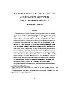
Three different concepts of the MOVE II payload are shown in Fig. 13: a CFRS reflector, a mast tensioning the membranes and both concepts combined. As can be seen in the left rendering, the parabolic CFRS shell-membrane antenna reflector shall be precisely unfolded during the mission, proving the feasibility of the small deployable reflector concept. In addition, this could be visually verified in orbit by a small video-camera system, mounted on an expandable mast. In future verification missions, this reflector-camera system could be modified to a reflector-feed system, thus enabling CBand or X-Band communication tests, depending on the reflector’s size. Flexible Copper Indium Gallium Selenide (CIGS) solar-cells could be applied on the reverse side of the membrane reflector, and/or around the deployable mast, further enhancing the electrical power produced on the satellite.
Fig. 13. Preliminary Studies of possible payloads for MOVE II. A parabolically shaped, deployable CFRSreflector carrying flexible solar cells and a camera for optical verification (left). A CFRS gravity-gradient mast with flexible solar cells on tensioned membrane (middle), a combination of both (right). 5.
SUMMARY
Preliminary studies for the upcoming CubeSat mission MOVE II show the potential of expandable reflectors or masts on CubeSats. They may overcome the current CubeSat limitations in available power or downlink data rate. Due to their large area-to-mass ratio they furthermore significantly increase drag and hence reduce orbit lifetime, thus assisting with space debris mitigation in LEO. Utilizing novel folding techniques for parabolic CFRS antennas, MOVE II may pave the way for C-Band or X-Band communication systems on CubeSats or for small satellites.
[1]. [2].
[3]. [4]. [5]. [6].
REFERENCES The CubeSat Program: CubeSat Standard CubeSat Design Specification Rev. 13, http://www.cubesat.org /index.php/documents/developers, Cal Poly, Saint Louis Obispo, USA, retrieved 21.07.2014. M. Czech, A. Fleischner and U. Walter: “A First-MOVE in Satellite Development at the TU-München”, in: Small Satellite Missions for Earth Observation, R. Sandau, H.-P. Roeser und A. Valenzuela, Springer Berlin Heidelberg, pp. 235-245, 2010. http://dx.doi.org/10.1007/978-3-642-03501-2_22. ClydeSpace: CubeSat Solar Panels, www.clyde-space.com/documents/2625, Clyde Space Limited, Glasgow, United Kingdom, retrieved 21.07.2014. Pumpkin Inc.: Pumpkin Price List, http://www.pumpkininc.com/content/doc/forms/pricelist.pdf, Pumpkin Incorporated, San Francisco, USA, retrieved 21.07.2014. J. Weaver, “ExoCube and a Gravity Gradient ADCS,” Proceedings of the AIAA/USU Conference on Small Satellites, CubeSat Developers' Workshop, SSC13-WK-20. http://digitalcommons.usu.edu/smallsat/2013/all2013/13/, 2013. Costantine, J.; Tawk, Y.; Christodoulou, C.G.; Banik, J.; Lane, S., "CubeSat Deployable Antenna Using Bistable Composite Tape-Springs," Antennas and Wireless Propagation Letters, IEEE , vol.11, no., pp.285,288, 2012. doi: 10.1109/LAWP.2012.2189544
Proceedings of the 2nd International Conference "Advanced Lightweight Structures and Reflector Antennas", 1 – 3 October 2014, Sheraton Metechi Palace Hotel, Tbilisi, Georgia
[7]. R. Hodgens, B. Shah, D. Muthulingham and T. Freeman, “ISARA – Integrated Solar Array and Reflectarray Mission Overview,” Proceedings of the AIAA/USU Conference on Small Satellites, CubeSatDevelopers' Workshop, SSC13WK-19. http://digitalcommons.usu.edu/smallsat/2013/all2013/12/, 2013. [8]. W. Rackl, Multi Purpose Deployment Mechanism for the MOVE Satellite, Semester Thesis, Technische Universität München, RT SA 2009/1, 2009. [9]. P. Reiss, E. Breunig, P. Zimmerhakl, N. Newie and A. Zeiner, “Investigating new space structures with the FOCUS experiment”, Proceedings of the 20th ESA Symposium on European Rocket and Balloon Programmes (PAC Symposium), ESA, 2011. [10]. SMARD Student Rocket Experiment: http://smard-rexus.de/, Technische Universität München, retrieved 21.07.2014. [11]. M Bille, P. Kolodziejski and T. Hunsaker, “Distant Horizons: Smallsat Evolution in the Mid-to-Far Term”, Proceedings of the AIAA/USU Conference on Small Satellites, Technical Session IV: On the Horizon, SSC11-IV1. http://digitalcommons.usu.edu/smallsat/2011/all2011/29/. [12]. A. Babuscia, B. Corbin, M. Knapp, R. Jensen-Clem, M. Van de Loo and S. Seager: “Inflatable antenna for cubesats: Motivation for development and antenna design”, in Acta Astronautica 91 (0), S. 322–332, 2013. DOI: 10.1016/j.actaastro.2013.06.005. [13]. B. Klofas, K. Leveque, “The Future of CubeSat Communications: Transitioning Away from Amateur Radio Frequencies for High-speed Downlinks”, in Proceedings of the 2012 AMSAT-NA Space Symposium and Annual Meeting, Orlando, Florida. Retrieved on 21.07.2014 from www.klofas.com/papers/. [14]. L. Datashvili, H. Baier, E. Wehrle, T. Kuhn and J. Hoffmann, “Large Shell-Membrane Space Reflectors”, In proc.: 51st AIAA/ASME/ASCE/AHS/ASC Structures, Structural Dynamics, and Materials Conference, 2010. DOI: 10.2514/6.2010-2504. [15]. H. Baier, L.Datashvili, Z. Gogava, E. Medzmariashvili, V.Montuori: Building blocks of large deployable precision membrane reflectors, In: Proceedings of the 42nd AIAA/ASME structures, structural dynamics and materials conference, AIAA paper no. 2001-1478, April 2001, Seattle. DOI: 10.2514/6.2001-1478. [16]. L. Datashvili, H. Baier, „Derivation of Different Types of Antenna Reflectors from the Principle of Highly Flexible Structures”, Proceedings of the EuCAP 2014 - The 8th European Conference on Antennas and Propagation, The Hague, The Netherlands, 6 – 11 April, 2014 [17]. Leri Datashvili, Nikoloz Maghaldadze, Stephan Endler, Julian Pauw, Peng He, Horst Baier, Alexander Ihle, Julian Santiago Prowald, “Advances in Mechanical Architectures of Large Precision Space Apertures”, Proceedings of the European Conference on Spacecraft Structures, Materials & Environmental Testing, 01 – 04 April, 2014, Braunschweig, Germany [18]. Leri Datashvili, “Foldability of Hinged-Rod Systems Applicable to the Deployable Space Structures”, CEAS Space J (2013) 5:157-168 [19]. L. Datashvili, H. Baier, “Flexible Fiber Composites for Space Structures”, chapter in the book “Fiber-Reinforced Composites”, Edited by G. Chang, pp. 605-640, ISBN: 978-1-61470-303-7 (hardcover), 2012, Nova Science Publishers, NY, USA [20]. L. Datashvili, H. Baier, L. da Rocha-Schmidt, "Multi-scale Analysis of Structures made of Triaxially Woven Fabric Composites with Stiff and Flexible Matrix Materials", proceedings of the 52th AIAA/ASME/ASCE/AHS/ASC Structures, Structural Dynamics, and Materials Conference 2011, Denver [21]. L. Datashvili, H. Baier, T. Kuhn, J. Hoffmann “Large Shell-Membrane Space Reflectors”, proceedings of the 51st AIAA/ASME/ASCE/AHS/ASC Structures, Structural Dynamics, and Materials Conference, 12 - 15 Apr 2010, Orlando, Florida [22]. L. Datashvili, “Review and Evaluation of the Existing Designs/Technologies for Space Large Deployable Apertures”, proceedings of the International Scientific Conference “Advanced Lightweight Structures and Reflector Antennas”, 14-16 October, 2009 Tbilisi, Georgia [23]. L. Datashvili, H. Baier, “Large Membrane Reflectors” Proceedings of the 3rd European Conference on Antennas and Propagation - EuCAP 2009, 23-27 March 2009, Berlin, Germany [24]. L. Datashvili, H. Baier, "Precision Deployable Shell-Membrane Antenna Reflector for Space Applications", Proceedings of the 59th International Astronautical Congress 2008, Glasgow, Scotland [25]. L. Datashvili, "Multifunctional and Dimensionally Stable Flexible Fibre Composites for Space Applications", Journal of the International Academy of Astronautics “Acta Astronautica”, 2009 (special issue: Glasgow)
Proceedings of the 2nd International Conference "Advanced Lightweight Structures and Reflector Antennas", 1 – 3 October 2014, Sheraton Metechi Palace Hotel, Tbilisi, Georgia
[26]. L. Datashvili, H. Baier, "Shell-Membrane Reflecting Surface Material for Deployable and Transformable Space Reflectors", Proc. ESA Conf. on Antennas, Noordwijk, Mai 2008 [27]. L. Datashvili, H. Baier, J. Schimitschek, M. Lang, and M. Huber, “High Precision Large Deployable Space Reflector Based On Pillow-Effect-Free Technology“; AIAA-2007-2186 Proceedings of the 48th AIAA/ASME/ASCE/AHS/ASC Structures, Structural Dynamics, and Materials Conference, 23 - 26 Apr 2007, Honolulu, Hawaii [28]. L. Datashvili, M. Lang, M. Huber, H. Baier, "Accuracy Study of a Space Deployable Antenna Reflecting Surface Under 0g and 1g Conditions”; Deutscher Luft- und Raumfahrtkongress 2006, 06.-10.11.2006, Braunschweig, Deutschland, published in the proceedings of 2007, band III-IV [29]. Lin Tze Tan “Stored Strain Energy Deployable Hybrid CFRP-CFRS Reflector Antennas”, proceedings of the International Scientific Conference “Advanced Lightweight Structures and Reflector Antennas”, 14-16 October, 2009 Tbilisi, Georgia [30]. Kuhn, T.; Langer, H.; Apenberg, S.; Wei, B.; Datashvili, L.: A Very Large Deployable Space Antenna Structure Based on Pantograph Tensioned Membranes. International Conference on Textile Composites and Inflatable Structures, Structural Membranes, CIMNE 2011, Barcelona, 2011 ACKNOWLEDGEMENTS The authors acknowledge the funding of First-MOVE by the Federal Ministry of Economics and Technology, following a decision of the German Bundestag, via the German Aerospace Center (DLR) with funding grant number 50 RU 0801 and the funding of SMARD by the DLR Mobile Rocket Base (MORABA).
Proceedings of the 2nd International Conference "Advanced Lightweight Structures and Reflector Antennas", 1 – 3 October 2014, Sheraton Metechi Palace Hotel, Tbilisi, Georgia