A new trend in the development of Parallel Kinematics. Manipulators (PKM) is the ... relative rotation of the mobile platform about a fixed point and are used as ...
Design and Development of 3-DOF Modular Micro Parallel Kinematic Manipulator C.C. Ng†, S.K. Ong* and A.Y.C. Nee*† †Singapore-MIT Alliance *Mechanical Engineering Department, Faculty of Engineering National University of Singapore, 9 Engineering Drive 1, Singapore 117576 This paper presents the research and development of a 3-legged micro Parallel Kinematic Manipulator (PKM) for positioning in micro-machining and assembly operations. The structural characteristics associated with parallel manipulators are evaluated and PKMs with translational and rotational movements are identified. Based on these results, a hybrid 3-UPU (Universal Joint-Prismatic Joint-Universal Joint) parallel manipulator is designed and fabricated. Kinematic algorithm and workspace visualization are presented for this hybrid 3-UPU manipulator. The principles of the operation and modeling of this micro PKM is largely similar to a normal size Stewart Platform (SP). A modular design methodology is introduced for the construction of this micro PKM. Calibration results of this hybrid 3-UPU PKM are discussed in this paper. Keywords: Micro parallel kinematic manipulator, modular design, Stewart Platform, workspace simulation. I. INTRODUCTION The recent trends towards high speed machining due to the demand for higher accuracy and greater dexterity have motivated the research and development of new novel types of parallel kinematics machines [1]. A parallel manipulator is a closed-loop mechanism where a moving platform is connected to the base by at least two serial kinematics chains (legs). The conventional Stewart Platform (SP) manipulator has six extensible legs and hence a very rigid kinematics structure [2]. Compared to serial kinematics manipulators, an SP has the desirable characteristics of high payload and rigidity. However, the drawback of an SP is a much limited working envelope, more complex direct kinematics and control algorithms, coupled problems of the position and orientation movements, as well as the precise spherical joints are difficult to manufacture at low cost [3]. A new trend in the development of Parallel Kinematics Manipulators (PKM) is the reduction from six DOFs to three. The decrease of DOFs of the PKM has advantages in workspace and cost reduction. However, a 3-DOF PKM provides less rigidity and DOFs. To overcome these shortcomings, PKMs with fewer than six DOFs have been actively investigated. Clavel [4] and Sternheim [5] reported a 4-DOF high speed robot called the Delta Robot. Lee and Shah [6] analyzed a 3-DOF parallel manipulator. Some 3-DOF parallel manipulator architectures provide pure relative rotation of the mobile platform about a fixed point and are used as pointing devices, wrists of manipulators and orienting devices [7, 8]. Furthermore, Tsai [9] introduced a
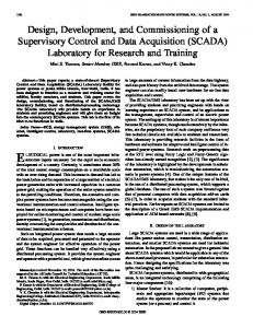
novel 3-DOF translational platform that is made up of only revolute joints. It performs pure translational motion and has a closed-form solution for the direct and inverse kinematics. In addition, a purely 3-DOF translational or rotational motion would require the activation of all the six legs, which means an increase in energy consumption [10]. Hence, in terms of cost and complexity, a 3-DOF 3-legged micro PKM is cost effective and the kinematics of the mechanism is further simplified for the purpose of control. To increase the flexibility and functionality of the micro PKM developed in this research, the concept of modular design has been introduced. In recent years, modular robots have increasingly been proposed as a means to develop reconfigurable and self-repairable robotic systems [11]. Modular robots consisting of many autonomous units or modules can be reconfigured into a large number of designs. Based on the modular design concept, three PKMs have been configured virtually for this research using a solid modeling system and the same modular components as shown in Fig. 1. In Fig. 1, platforms with only rotational movements, translational movements, as well as a hybrid UPU platform can be assembled by interchanging the spherical and the universal joints or adding extra rigid links.
Fig. 1 Parallel manipulator systems fabricated using the same modular components.
Ideally, the modules should be uniform and self-contained. These modules must interact with one another and co-operate to realize self-configuration. The robot can change from one configuration to another manually or automatically. Hence, a modular manipulator can be reconfigured or modified to adapt to a new environment. In addition, a modular micro PKM can have self-repairing capability by removing and replacing failed modules. Since self-reconfigurable modular robots can provide the functionality of many traditional mechanisms, they are especially suited for a variety of tasks, such as high speed machining [1] in the precision engineering industry.
II. BACKGROUND
III. MATHEMATICAL MODEL
In this research, the objectives of the development of the micro PKM, i.e., Micro Parallel Kinematic Manipulator (MSP) are the minimization of the dimensions of the system and the portability of the system, e.g., portable on a CNC machine. For the minimization of the dimensions of the MSP, the number of links of the platform is reduced from six to three. The DOF for a closed-loop PKM is examined using the Grübler’s formula:
To analyze the kinematics model of the parallel mechanism, two relative coordinate frames are assigned, as shown in Fig. 3. A static Cartesian coordinate frame XBYBZB is fixed at the center of the base while a mobile Cartesian coordinate frame XPYPZP is assigned to the center of the mobile platform. Pi, i = 1, 2, 3 and Bi, i = 1, 2, 3 are the joints that are located at the center of the base and the platform passive joints respectively. A passive middle link Lm is installed at the middle of the platform to constrain the kinematics of the platform to perform translation along the Z-axis and rotational around the X- and Y-axes. Let rB and rP be the radii of the base and the platform passing though joints Pi and Bi (i = 1, 2, 3), respectively. The position of Bi with reference to the fixed coordinate frame XBYBZB can be expressed in equation (2).
Fe = λ (l − j − 1) +
j
∑f
i
− Id
(1)
i =1
where Fe is the effective DOF of the assembly or mechanism, λ is the DOF of the space in which the mechanism operates, l is the number of links, j is the number of joints, fi is the DOF of the i-th joint, and Id is the idle or passive DOFs. The number of joints is nine (six universal joints and three prismatic joints). The number of links is eight (two links for each actuator, the end effectors and the base). The sum of all the DOFs of the joints is 15. Hence, using Grübler’s formula, the DOF of the micro PKM is computed as F = 6(8 − 9 − 1) + 15 = 3 . Using a systematic enumeration methodology developed by Tsai [14], a comparison study of the configurations is performed to select a configuration that meets the requirement of the parallel kinematics system to be constructed in this research. Therefore, various designs of PKMs are simulated on a micro scale using Matlab, such as a 6-legged SP, 3-legged PKM and 6-legged PUS SP, where PUS denotes a platform with links of prismatic joint, universal joint and spherical joint. The workspace of these platforms are simulated as shown in Fig.2, and compared to select the most suitable design to achieve the research objectives.
Fig. 3 Schematic diagram of the PKM.
B1 = [rB ⎡ 1 B 3 = ⎢ − rB ⎣⎢ 2
0 0]T
−
3 rB 2
⎡ 1 B2 = ⎢ − rB ⎣⎢ 2
⎤ 0⎥ ⎦⎥
3 rB 2
⎤ 0⎥ ⎦⎥
T
T
(2)
The positions of joints Pi, (i = 1, 2, 3) are expressed with respect to the mobile frame XPYPZP in equation (3). a
b
P1 = [rP
⎡ 1 P3 = ⎢− rP ⎣ 2
c Fig. 2(a) 6-legged micro Stewart Platform, (b) 3-legged micro Stewart Platform, and (c) PSU micro Stewart Platform.
0 0]
T
−
3 rP 2
⎡ 1 P2 = ⎢− rP ⎣ 2 ⎤ 0⎥ ⎦
T
3 rP 2
⎤ 0⎥ ⎦
T
(3)
Since the proposed MSP is to be built within a limited space of 300mm × 300mm × 300mm, the actuators with length of 216mm are too long to be assembled directly onto the base joints. Instead of assembling the actuators on top of the joints, the actuators are aligned parallel to the joints as shown in Fig. 4. Therefore, the calculation of the length of the link is not as direct as the inverse kinematics of a normal
SP. As shown in Fig. 5, the length of the link can be calculated using equation (4). r r r v li = − Bi + t + R ⋅ Pi , i = 1 ... 3 (4)
r
where li is the dotted link length, and t and R are the translation and orientation of Pi with respect to [XP YP ZP]T. However, for this present hybrid PKM, extra calculation steps in equations (5)-(8) are needed as shown in Fig. 4. x2 + a2 = y2 (5)
k −x z L− y xL = = ⇒y= x a y k x=
(6)
Virtual Actuator
[
which are 0°, 120° and 240°. Besides, Bi = rxi
ryi
]
0T,i
= 1, 2, 3 is also known from equation (3). Based on inverse kinematics of the platform, one can determine the ⎡ Px ⎤ ⎢ i⎥ point ⎢ Pyi ⎥ , i = 1, 2, 3 from equation (4). ⎢P ⎥ ⎣ zi ⎦
(7)
a2 L2 ( 2 ) −1 k
⎛ a2 ⎜k − 2 ⎜ L ⎜ −1 k − x ⎜ k2 z = a× =⎜ x a2 ⎜ 2 ⎜ L ⎜⎜ −1 k2 ⎝
variables are eliminated among these equations as shown in Fig. 5. Let X = α , Y = β , Z = σ and Li+H = Mi, since Li is known from the similarity triangle equation. Furthermore, Zi (i = 1, 2, 3) is known based on the coordination of each base joints,
⎞ ⎟ ⎟ ⎟ ⎟ ⎟×a ⎟ ⎟ ⎟⎟ ⎠
(8)
Actuator
Fig. 5 Geometry method diagram.
Thus, for a known platform position, one can calculate the rotation angles, Xi and Yi based on the known actuator stroke length using equation (9). ∴ R z × R xy Fig. 4 Calculation of the actual stroke of the link.
By determining the length of the dotted link, Li using inverse kinematics, the length of Z can be determined using the similarity triangular theory as shown in equation (8). Hence, the strokes of the links can be found indirectly based on the manipulation of the platform. After analyzing the stroke through inverse kinematics methods, the required rotational angle of the base joints and platform joints can be further affirmed through determining the angles of rotation as shown in Fig. 5. The geometry matrix method of analysis was used since for parallel manipulators, it is often more convenient to employ the geometric method [12]. Generally, a vector-loop equation is written for each limb, and the passive joint
⎡ 0 ⎤ ⎡ rxi ⎤ ⎡ Pxi ⎤ ⎢ ⎥ × ⎢⎢ k i ⎥⎥ + ⎢⎢r yi ⎥⎥ = ⎢ Pyi ⎥ ⎢⎣ Mi ⎥⎦ ⎢⎣ 0 ⎥⎦ ⎢ Pz ⎥ ⎣ i⎦
(9)
where, ⎡cos Z i Rz = ⎢⎢ sin Z i ⎢⎣ 0
− sin Z i cos Z i 0
0⎤ ⎡ cos Yi and RXY = ⎢⎢ 0 0⎥⎥ ⎢⎣− sin Yi 1⎥⎦
sin Yi sin X i cos X i cos Yi sin X i
sin Yi cos X i ⎤ . − sin X i ⎥⎥ cos Yi cos X i ⎥⎦
Hence, through elaboration of equation (9), the solutions for the rotation angle X i , Yi where i = 1, 2, 3 can be found. Hence, through determining the rotation angle of each universal joint of the links, the stroke of the actuators can be determined. The known rotation angle is also used as a geometry constraint to determine the workspace of the platform. After the determination of the stroke and angle of rotation of all the universal joints of the actuators, a
simulated hybrid 3-UPU PKM can be plotted using Matlab as shown in Fig. 6. A passive middle link is installed and attached via a spherical joint to the platform as shown Fig. 7. The passive middle link acts as a constraint for the extra DOF of the platform. The inverse and forward kinematics algorithms of this hybrid PKM are implemented using Matlab, and the movement of the platform is simulated to verify the mobility of the platform.
Cartesian coordinates of point P are recorded in the workspace database.
Fig. 7 Relationship between the point P and the spherical joint S.
Fig. 6 Modified SP with a passive prismatic middle link.
IV. OPTIMIZATION METHOD AND ANALYSIS OF WORKSPACE Based on the inverse and forward kinematics algorithms of the platform, and due to the fact that all legs are equal and the distance between the joints at the base and platform are equilateral, the workspace of the hybrid 3-UPU platform depends on three geometric parameters, namely, (a) the stroke of the prismatic link, Li, (b) the limitation of the universal joints angle of the base and platform, which is 45° and (c) the distances K between the spherical joint of the middle link to the middle point of the moving platform as shown in Fig. 7. The stroke Li of the actuator is the travel range of each prismatic link, which is 50mm. As shown in Fig. 8, the workspace describes the manipulation of point P, which is at the middle of the mobile platform, with respect to the middle point B of the base, as shown in Fig. 5. For each orientation of the platform, the middle point P is rotated with respect to point S at the center of the spherical joint, which is located at the middle link of the platform as shown in Fig. 7. During the optimization process, each position of the point P at the mobile platform is verified with its geometry constraints for every manipulation of the platform. The lengths of the legs are determined using inverse kinematics, i.e., equation (8). Next, the lengths of the legs are checked to determine if they are within the allowable interval Lmin