Design and Implementation of the Software Architecture for a 3-D Reconstruction System in Medical Imaging Holger Scherl
Stefan Hoppe
Markus Kowarschik
University of Erlangen-Nuremberg Institute of Pattern Recognition Martensstr. 3, D-91058 Erlangen, Germany
University of Erlangen-Nuremberg Institute of Pattern Recognition Martensstr. 3, D-91058 Erlangen, Germany
Siemens Medical Solutions P.O.Box 3260, D-91050 Erlangen, Germany
[email protected]
[email protected] Joachim Hornegger
markus.kowarschik @siemens.com
University of Erlangen-Nuremberg Institute of Pattern Recognition Martensstr. 3, D-91058 Erlangen, Germany
[email protected] ABSTRACT
[Image Processing and Computer Vision]: Reconstruction
The design and implementation of the reconstruction system in medical X-ray imaging is a challenging issue due to its immense computational demands. In order to ensure an efficient clinical workflow it is inevitable to meet high performance requirements. Hence, the usage of hardware acceleration is mandatory. The software architecture of the reconstruction system is required to be modular in a sense that different accelerator hardware platforms are supported and it must be possible to implement different parts of the algorithm using different acceleration architectures and techniques. This paper introduces and discusses the design of a software architecture for an image reconstruction system that meets the aforementioned requirements. We implemented a multi-threaded software framework that combines two software design patterns: the pipeline and the master/worker pattern. This enables us to take advantage of the parallelism in off-the-shelf accelerator hardware such as multi-core systems, the Cell processor, and graphics accelerators in a very flexible and reusable way.
General Terms Design, Algorithms, Performance
Keywords Software Design and Architecture, Patterns, Medical Imaging, 3-D Reconstruction, Hardware Abstraction Layer, Hardware Acceleration, Parallel Programming
1.
MOTIVATION
Scanning devices in medical imaging acquire a huge amount of data, e.g. X-ray projection images from different angles around the patient. Modern C-arm devices, for instance, generate more than 2 GigaByte (GB) of projection data for volume reconstruction. The basic computational structure of a reconstruction system consists of a series of processing tasks on these data, which finally results in the reconstructed volume, consisting of many transaxial slices through the patient. The typical medical workflow especially for interventional imaging using C-arm devices requires high-speed reconstruction in order to avoid a delay of patient treatment during surgery, for example. Because of this reason, future practical reconstruction systems may present the reconstructed volume to the physician in real-time, immediately after the last projection image has been acquired by the scanning device. This requires to do all computations on-the-fly, which means that the reconstruction must be done in parallel to the data acquisition. In this paper we focus on the design of a software architecture for the reconstruction system that can deal with the described requirements. Our proposed architecture is based
Categories and Subject Descriptors D.2.11 [Software Engineering]: Software Architectures— Patterns ; J.3 [Life and Medical Sciences]: Health; I.4.5
Permission to make digital or hard copies of all or part of this work for personal or classroom use is granted without fee provided that copies are not made or distributed for profit or commercial advantage and that copies bear this notice and the full citation on the first page. To copy otherwise, to republish, to post on servers or to redistribute to lists, requires prior specific permission and/or a fee. ICSE’08, May 10–18, 2008, Leipzig, Germany. Copyright 2008 ACM 978-1-60558-079-1/08/05 ...$5.00.
661
upon a combination of parallel design patterns [6]. The main part of the reconstruction system follows the pipeline pattern [8, 12] in order to organize the different processing tasks on the input data in concurrently executing stages. Achieving the objective to meet the immense computational demands on the reconstruction system, hardware acceleration of the respective processing tasks must be used in addition to the pipeline design. Nowadays, off-the-shelf accelerator hardware like multi-processor, multi-core systems, the Cell Broadband Engine Architecture (CBEA), and graphics accelerator boards may be used for this task. According to our experience, these massively parallel architectures can be used most efficiently by following the master/worker design pattern [6] in order to parallelize the computations of the respective pipeline stages. Another advantage of our approach is its role as a hardware abstraction layer. The master/worker concept allows to abstract from the respective hardware accelerator used in a specific pipeline stage. In combination with the Factory design pattern [1, 3] most parts of the overall reconstruction algorithm can be expressed independently from the used acceleration hardware. The respective architecture execution configuration of the pipeline stages can even be changed dynamically at run-time. We have done a thorough evaluation of the proposed design approach by implementing several reconstruction systems using the aforementioned hardware platforms [11, 9, 10]. While the basic building parts as described by the combination of the pipeline and the master/worker design patterns remain the same for all reconstruction systems, we implemented this design paradigm using a multi-threaded approach in a software framework called Reconstruction Toolkit (RTK). The framework further addresses resource usage issues when allocating objects in the pipeline, e.g. the allocation and management of buffers for input data. In the following section we will briefly describe a stateof-the-art reconstruction system using an example of reconstruction in computed tomography (CT) with C-arm devices. Then, we will comment on the technical facts of the considered hardware architectures used to implement accelerated versions of such a system. In Section 4 we will discuss in detail the design of a reconstruction system, which faces all important building blocks of its software architecture: the reconstruction pipeline (4.1), the parallelization strategy (4.2) and the resource management (4.3). The following section will reflect the practical challenge in implementing the design in a software framework that is flexible, reusable and easy to extend. Finally, we will conclude our work.
Load projections
Preprocess
Filter Data flow: Projection Volume
Back-project
Postprocess
Store volume
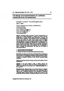
Figure 1: Processing steps of a state-of-the-art CT reconstruction system. ecution time [5]. For each projection image and for each discrete volume element (voxel), the intersection of the corresponding X-ray beam with the detector is computed and the respective detector intensity is accumulated to the current voxel. Figure 1 illustrates the processing steps in the order of occurrence. For a more detailed discussion of the algorithms we refer to [13] and [14].
3.
TARGET HARDWARE PLATFORMS
Due to the immense processing requirements of any reconstruction system, acceleration with special hardware is mandatory in order to meet the requirements of today’s medical workflow. Even acceleration boards based upon FPGA technology have been used in commercial reconstruction systems [5]. A combination of hardware using off-the-shelf technology may also be used for this task. Today, graphics accelerator boards, the CBEA, multi-core and multi-processor systems seem to be the most promising candidates. A significant advantage of these acceleration platforms over FPGA solutions is that their implementation requires much less development effort than FPGA-based solutions.
3.1
Multi-Core and Multi-Processor Systems
Nowadays, all relevant reconstruction systems are based upon this type of hardware. These systems are considered as the basic building block in every reconstruction system. The control flow of any reconstruction algorithm and some parts of it will be implemented on these processors. However, the processing power is still insufficient to achieve the reconstruction speed that is required in interventional environments. In addition, the computationally most expensive tasks can be accelerated using special hardware architectures.
3.2
Cell Broadband Engine Architecture
The CBEA [7] introduced by IBM, Toshiba, and Sony is a special type of a multi-core processing system consisting of a PowerPC Processor Element (PPE) together with eight Synergistic Processor Elements (SPEs) offering a theoretical performance of 204.8 Gflops1 (3.2 GHz, 8 SPEs, 4 floating point multiply-add operations per clock cycle) on a single chip. The processor is still completely programmable using high level languages such as C and C++. The major challenge of porting an algorithm to the CBEA is to exploit the parallelism that it exhibits. The PPE, which is compliant with the 64-bit Power architecture, is dedicated to host a Linux operating system and manages the SPEs as resources for computationally intensive tasks. The SPEs support 128 bit vector instructions to execute the same op-
2. CONE-BEAM CT RECONSTRUCTION In this section we briefly recapitulate the computational steps involved in a state-of-the-art CT reconstruction system (e.g. a C-arm CT device) that is based upon the FDK reconstruction method [2]. The reconstruction process can be subdivided into several parts [5]: 2-D preprocessing of the X-ray projection images, high-pass filtering in frequency domain of the X-ray projection images, back-projection and 3-D post-processing. Each projection image is processed instantaneously when it is transferred from the acquisition device over the network or, alternatively, when it is loaded from the hard disk. The back-projection is the computationally most expensive step and typically accounts for more than 70% of the overall ex-
1
662
1 Gflops = 1 Giga floating point operations per second
projected into the resulting volume data set. The pipeline pattern should be applied to build configurable data-flow pipelines. In our design we use a combination of the pipeline patterns that are described in [8, 12]. In the following we review the pipeline design pattern in the context of a reconstruction system. From the software engineering point of view, the pipeline design pattern provides the following benefits for the reconstruction system architecture:
erations simultaneously on multiple data elements (SIMD). In case of single precision floating point values (4 byte each) four operations can be executed at the same time. The SPEs are highly optimized for running compute-intensive code. They have only a small memory each (local store, 256 KB) and are connected to each other and to the main memory via a fast bus system, the Element Interconnect Bus (EIB). The data transfer between SPEs and main memory is not done automatically as is the case for conventional processor architectures, but is under complete control of the programmer, who can thus optimize data flow without any side effects of caching policies.
• It allows to decouple the compositional structure of the processing tasks in a specific algorithm from the implementation that computes the respective tasks.
3.3 Common Unified Device Architecture
• It is possible to set up the pipeline in a type-safe and pluggable manner. Type-safe means that the type of data that is sent through the different pipeline stages can be defined and enforced statically by the compiler.
In comparison to the nine-way coherent CBEA, modern GPUs offer even more parallelism by their SIMD design paradigm. The NVIDIA GeForce 8800 GTX architecture, for example, uses 128 Stream Processors in parallel. This GPU (345.6 Gflops1 , 128 stream processors, 1.35 GHz, one multiply-add operation per clock cycle per Stream processor) is theoretically capable of sustaining almost twice the performance of the CBEA. Recently, NVIDIA has provided a fundamentally new, and easy-to-use computing architecture for solving complex computational problems on the GPU. It is called the Common Unified Device Architecture (CUDA). It allows to implement graphics-accelerated applications using the C-programming language with a few CUDA-specific extensions. The programs, which are executed on the graphics device, are called kernels. A graphics context must be initialized and bound to a thread running on the host system. The execution of the kernels must be initiated from this thread, which must be addressed in the design of the software architecture.
• The pipeline can be both configured and reconfigured dynamically and independently from reusable components. Depending on the used reconstruction algorithm, the order of both control and data messages that are sent through the pipeline stages must often be preserved. This is easy to realize using the pipeline approach, because the pipeline design pattern depends upon the flow of data between stages.
4.1.2
4. RECONSTRUCTION SYSTEM DESIGN Throughout the discussion of our reconstruction system design we suppose that the whole system is primarily based upon a general-purpose computing platform either as a singlecore or multi-core system. This system may be extended by several hardware accelerators either on-chip or as an accelerator board. For this reason, the design must allow the acceleration by specific hardware architectures at each part of the algorithm. It is also required that several different hardware architectures can be used for different processing steps.
• The slowest pipeline stage will determine the aggregate reconstruction speed. • Communication overhead can affect the performance of the application, especially when only few computations are executed in a pipeline stage. In a reconstruction system, the granularity of the data flow between pipeline stages can be considered to be large, because most often projection images will flow through the pipeline as a whole. On shared-memory architectures, the number of computations that are performed on the projection images is high in comparison to the communication overhead.
4.1 Reconstruction Pipeline As can be seen in Figure 1 the overall computation of the reconstruction system involves performing calculations on a set of 2-D projection images, where the calculations can be viewed in terms of the projections flowing through a sequence of stages. We use the pipeline design pattern [6] to map the blocks (stages) of Figure 1 onto entities working together in order to form a powerful software framework which is both, reusable, as well as easy to maintain and to extend.
4.1.1
Concurrency
Within the pipeline design pattern, the concurrent execution of the different stages is possible using a multi-threaded design approach. This allows us to compute the different parts of the reconstruction algorithm in parallel. The following factors will affect the performance of reconstruction systems that are based upon this pattern:
• The amount of concurrency in the pipeline is limited by the number of pipeline stages and a larger number of pipeline stages is preferable. In a reconstruction system this number depends upon the reconstruction algorithm and is therefore limited considering a pipeline flow with a granularity of projection images. • The time required to fill and drain the pipeline should be small compared to the overall running time. Since reconstruction systems process a large amount of projections, this point can be ignored in this context.
Pipeline Design Pattern
Software systems where ordered data passes through a series of processing tasks are ideally mapped to a pipeline architecture [6]. This is especially true for any CT reconstruction system where hundreds of X-ray projection images have to be processed in several filtering steps and are then back-
Nonetheless, for a reconstruction system, the amount of concurrency offered by the pipeline pattern is by far insufficient. We therefore consider the pipeline architecture only as the
663
4.2.2
basic building block of the overall reconstruction system architecture that structures and simplifies its implementation and enables basic concurrent processing. As will be described in Section 4.2, the actual strength of the pipeline design comes into play when we combine this pattern with the master/worker pattern for selected pipeline stages in order to make use of special accelerator hardware.
From a macroscopic point of view, our software architecture consists of a pipeline structure. In order to overcome the limited flexibility and concurrency in the pipeline design pattern (see Section 4.1.2), further refinement of the pipeline stages is necessary. We propose a software design of the reconstruction system that allows a hierarchical composition of the pipeline and the master/worker design patterns. This allows to integrate a master and a configurable number of workers in a pipeline stage. In the context of our reconstruction task we have found that it is sufficient to have only a hierarchy depth of one, which means that it must only be possible to integrate master/worker processing in a pipeline stage but there is no need to have a pipeline nested in a specific worker. This procedure totally closes the gap of limited support for flexibility and concurrency in the pipeline pattern. A centralized approach with only one master process can easily become a bottleneck when the master is not fast enough to keep all of its workers busy. It also prohibits an optimal usage of the acceleration hardware because its processing power still has to be assigned or partitioned statically to specific pipeline stages. For this reason, we extend our design such that it allows to share processing elements between several master/worker pipeline stages (see Section 4.3.1).
4.2 Parallelization Strategy As was outlined in the previous section, the pipeline design pattern is able to act as the basic building block of a reconstruction system. In order to achieve the reconstruction speed necessary for the typical medical workflow, the level of concurrency in the pipeline design is still not sufficient and flexible enough. Therefore, the software architecture of a reconstruction system has to be extended by including other possibilities of achieving concurrency. In this section we show how the gap can ideally be filled when combining the master/worker [6] design pattern with the pipeline design pattern.
4.2.1
Combination with the Pipeline Design Pattern
Master/Worker Design Pattern
The master/worker design pattern is particularly useful for embarrassingly parallel problems that can be faced by a task parallelization approach [6]. The most computationally expensive task in a reconstruction system, the backprojection, is of such type. The master/worker approach is also applicable to a variety of parallel algorithm structures and it is possible to use it as a paradigm for hardware accelerated algorithm design on many different architectures. In the following we review the master/worker design pattern in the context of a reconstruction system. The master divides the problem in manageable tasks, which we will call work instruction blocks (WIBs), and sends them to its workers for processing. For example, the backprojection computation can be partitioned into several WIBs, each corresponding to a small sub-volume. Then, each worker processes in a loop one WIB after the other and sends the respective results back to the master. When the master received all WIBs corresponding to a specific task, the processing of that task is finished. A parallelization strategy based upon the master/worker pattern has the following characteristics:
4.2.3
Hardware Abstraction
The master/worker design paradigm can be used to parallelize most parts of a specific reconstruction algorithm and it is not tied to any particular hardware. The approach can be used for everything from clusters to shared-memory architectures. It can thus act as a hardware abstraction layer in the reconstruction system. The basic functionality and communication mechanisms of the master/worker pattern have to be implemented only once for each supported hardware architecture, and different load balancing strategies can be integrated in its communication abstraction. This is necessary because for a specific hardware architecture, a certain load balancing strategy may be better than another one. For example, using a CUDAcapable platform, the sharing of resources in device memory among a task-group can require static load balancing. In contrast to this, the CBEA always performs best with a dynamic load balancing approach, since no resources are shared in local store among task-groups. In reconstruction systems, several hardware components may be used for the acceleration of different parts of the reconstruction algorithm. The combination of the pipeline and master/worker pattern has enough flexibility to support such heterogeneous systems allowing the usage of different acceleration hardware solutions in each pipeline stage. A specific part of the reconstruction algorithm may be mapped to the best suited acceleration hardware independently of the processing order. For example, multi-core systems may be used in between GPU-accelerated parts of the algorithm. In combination with the factory design pattern [1, 3], most parts of the overall reconstruction algorithm can be expressed independently from the used acceleration hardware. This allows for a portable and flexible algorithm design that reuses the common parts and even enables the respective architecture execution configuration of the pipeline stages to be changed dynamically at run-time.
• Static and dynamic load balancing strategies can be applied for the distribution of the tasks to the workers. Both strategies are easy to realize. In Section 4.2.3 we will see that this is particularly important for hardware abstraction in our design. • Master/worker algorithms have good scalability as long as the number of WIBs significantly exceeds the number of workers. • The processing time of a task must be significantly higher than the necessary communication overhead to distribute it to a worker and back to the master. The last two characteristics can easily be enforced in the considered medical imaging applications. For performance reasons all worker processes should be created when the pipeline is initialized. This saves the overhead resulting from frequent creation and termination of worker processes.
664
4.3 Resource Management
pipeline stage. For example, the projection buffers can be acquired in the first stage of the pipeline and released in the back-projection stage after processing. In order to support the multi-threaded software framework, the object pool can be based upon a shared queue object [6]. The pool will block any pop requests when no more data buffers are available and unblocks the respective request immediately as soon as a data buffer has been released to the pool.
Another important aspect in the design of a reconstruction system is the resource management. We distinguish the relevant resources of the considered target hardware platforms into two classes: processing elements and data buffers. In the following we will show how a sophisticated resource management can easily be integrated in the reconstruction system design for both processing elements and data buffers.
4.3.1
Processing Elements
5.
As was outlined in Section 4.2.2, processing elements have to be statically assigned to special master/worker pipeline stages, which prohibits an optimal usage of the acceleration hardware. For this reason we want to share processing elements between several master/worker pipeline stages. This is achieved by extending the single master methodology to support multiple masters, each of them living in a different pipeline stage, but still using the same group of workers. In this respect, the design is enhanced by an improved scalability and also by a reduction of the limitation that the slowest pipeline stage determines the aggregate reconstruction speed. Load is now automatically balanced between pipeline stages with master/worker processing capability that are using the same group of workers. Only this extension enables an optimal usage of the considered hardware architectures:
We implemented the discussed design approach in a software framework called Reconstruction Toolkit (RTK). In the following we present the basic building blocks of our implementation. We abstract from all details that are not relevant to understand the basic structure of our implementation.
5.1
Structure
The UML class diagram in Figure 2 illustrates the inheritance hierarchy of our design approach.
5.2
Participants
All entities live in the ”rtk” namespace which we don’t qualify in the following for enhanced readability. • InputSide defines the input interface of a pipeline stage for data items and control information.
• In multi-processor and multi-core systems, thread switching overhead can be reduced by controlling the overall number of used threads. • With regard to the CBEA, resource usage of the processing elements is especially improved by sharing the SPEs between pipeline stages. It is therefore necessary to technically compile each worker side of the shared pipeline stages into one associated SPE program. This may result in too large SPE program binaries which do not fit into the local store any more. Such programs can effectively be handled by using the overlay technique which loads the required program code dynamically.
• OutputSide defines the output interface of a pipeline stage for data items and control information. • Stage combines an InputSide with an OutputSide to create an interior pipeline stage. • SourceStage is the first pipeline stage in a pipeline. The source stage creates its input data items for its own in a separate thread of control and provides a mechanism for the application to start the execution of the pipeline. • SinkStage is the last pipeline stage in a pipeline. It provides a mechanism for the application to wait for a result and to get it from the pipeline. • Port manages the connection of two stages and provides the mechanism for output. The port concept enables the dynamic composition of two pipeline stages with active and passive read or write semantics [12] at run-time and without a complex class hierarchy.
• In CUDA development, the considered design allows to share a single graphics context and thus GPU device resources among different pipeline stages, which avoids expensive data transfers between device and host memory.
4.3.2
IMPLEMENTATION
• NestedPort manages the connection of two stages with active write and passive read semantics [12] in that order. The stages connected by this mechanism are sharing the same thread of execution.
Data Buffers
In a reconstruction system, resource management must also be addressed for data buffers, because the allocation of memory for all buffers is not always feasible. For example, the reconstruction of a typical medical data set in C-arm CT requires up to three GB to store the reconstruction volume together with all projections. It is therefore necessary to allocate only a limited number of data buffers. That means that only a few projection images and the reconstruction volume may be used during reconstruction. In order to avoid the frequent allocation and deallocation of memory, which is an expensive operation, we reuse projection and volume buffers after they have been processed. This can be achieved by using the object pool pattern [4]. By introducing this design paradigm, data buffers can be acquired from the pool and released to the pool in any
• ThreadedPort manages the connection of two stages with active write and active read semantics [12] in that order. The stages connected by this mechanism will run in different threads of execution. • MasterStage is the pipeline stage that is responsible for partitioning the processing into WIBs (scattering) and to respond to processed WIBs (gathering). The communication with its corresponding WorkerStage is done by a concrete Master. The MasterStage must therefore register at a concrete Master in order to use its communication abstraction and the processing elements that are managed by the corresponding Master.
665
NestedPort
TOutput TConfigOut
TOutput TConfigOut
Port Attach(InputSide) Detach() Output(TConfigOut) Output(TOutput)
Output(TConfigOut) Output(TOutput)
0..1
SinkStage Wait()
Output(TConfigOut) Output(TOutput)
0..1
TOutput TConfigOut
TInput TConfigIn
InputSide Input(TConfigIn) Input(TInput)
ThreadedPort
OutputSide Attach(Port) Detach() Output(TConfigOut) Output(TOutput)
0..1
0..1
TInput TConfigIn TOutput TConfigOut
TInput TConfigIn
TOutput TConfigOut
Stage Start() Stop() Finish()
SourceStage Start()
TOutput TConfigOut
TInput TConfigIn TOutput TConfigOut TWib TIib TWorkerStage
0..1
MasterStage InputWib(TWib) OutputWib(TWib) AcquireWib() : TWib ScatterWibs(TInput) GatherWibs(TInput, TWib) IsProcessed(TInput) : bool
TIib TWib
WorkerStage Init(TIib) InputWib(TWib) 0..1
0..*
Master
0..*
0..1
InputWib(Wib) OutputWib(Wib)
Worker
0..*
InputWib(Wib) OutputWib(Wib)
Figure 2: UML class diagram of the inheritance hierarchy of our design approach. The classes used to implement the pipeline pattern are shown in light gray. The combination with the master/worker pattern is illustrated by the added classes in dark gray.
666
• WorkerStage does the processing of a WIB for a corresponding MasterStage. All communication with the corresponding MasterStage is taken over by the corresponding concrete Master that controls this stage and the respective Worker.
return new FltMasterPc ( m as t e r P c ) ; } // C r e a t e s t h e back−p r o j e c t i o n s t a g e w i t h // hardware a c c e l e r a t i o n u s i n g CUDA i n l i n e BpStage ∗ CreateBpStage ( ) { return new BpMasterCuda ( masterCuda ) ; } private : MasterPc m as t e r P c ; MasterCuda masterCuda ; };
• Master provides the basic functionality for the application of the master/worker pattern. While it functions as the hardware abstraction layer a concrete Master must be implemented for each supported architecture. The Master also creates the corresponding concrete Workers for the respective architecture. The Master allows one or more MasterStages to connect to it and also initiates the creation of the corresponding WorkerStages.
The preprocessing and back-projection pipeline stage share the same master, which also enables to share the two CUDAenabled GPUs for their processing. The classes PrepMasterCuda, FilterMasterPc and BpMasterCuda implement the respective algorithms in an accelerated version using the mentioned hardware platforms. For the sake of this example we give a sketch of the back-projection implementation using the two CUDA-enabled GPUs. We have to implement two classes - the master pipeline stage BpMasterCuda and the corresponding worker stage BpWorkerCuda:
• Worker implements the processing node of the corresponding Master. A concrete Worker must be implemented for each supported architecture. The actual processing of a WIB is switched to the corresponding WorkerStage which shall do the processing.
// I i b i s t h e t y p e o f a i n i t i n s t r u c t i o n b l o c k // Wib i s t h e t y p e o f a work i n s t r u c t i o n b l o c k
5.3 Sample Code and Usage The following code samples illustrate how the CT reconstruction system from Section 2 could be implemented in C++. We concentrate on the implementation of this application using the RTK framework rather than going into the implementation details of the framework itself. As an example we assume that we want to accelerate the filtering step of the application using a general purpose multi-core platform and the preprocessing and back-projection shall be accelerated using two CUDA-enabled graphics cards. We intentionally skipped the postprocessing step in order to shorten the sample implementations. The creation of the concrete stages that build up the pipeline is done by the factory class PcCudaFactory that implements the abstract factory providing the interface to the used methods. We refer to [3] and [1] for more details about the factory and abstract factory pattern.
c l a s s BpWorkerCuda : public WorkerStage { private : v i r t u a l void I n i t ( const I i b& i i b ) { bp init cuda ( iib ); } v i r t u a l void InputWib ( const I i b& i i b , Wib& wib ) { b p p r o c e s s c u d a ( i i b , wib ) ; } }; c l a s s BpMasterCuda : public MasterStage { private : v i r t u a l void C o n f i g u r e ( const Param& c o n f i g ) { c u r r e n t V o l u m e = CreateVolume ( c o n f i g ) ; } v i r t u a l void F i n i s h ( ) { Output ( ∗ c u r r e n t V o l u m e ) ; currentVolume = 0 ; } v i r t u a l void S c a t t e r W i b s ( P r o j& p r o j ) { // p r o c e s s a l l sub−volumes f o r ( i n t i =0; i