This is copy is maintained as a self-archive. Please see below to obtain a copy from the publisher. Technology and Innovation, Vol. 15, pp. 297–300, 2014 Printed in the USA. All rights reserved. Copyright 2014 Cognizant Comm. Corp.
1949-8241/14 $90.00 + .00 DOI: http://dx.doi.org/10.3727/194982413X13844488878970 E-ISSN 1949-825X www.cognizantcommunication.com
Design and Performance of a Push-Up Device for Above-Elbow Amputees: A Technical Note Matthew M. Wernke,*† Derek J. Lura,*† Stephanie L. Carey,*† and M. Jason Highsmith‡§ *Department of Mechanical Engineering, University of South Florida, Tampa, FL, USA †Center for Assistive, Rehabilitation, and Robotics Technologies, University of South Florida, Tampa, FL, USA ‡School of Physical Therapy and Rehabilitation Sciences, University of South Florida, Tampa, FL, USA §Center for Neuromusculoskeletal Research, University of South Florida, Tampa, FL, USA This article provides details on the design and performance of a push-up device for above-elbow amputees. The push-up performance of a transhumeral amputee using a push-up device was compared with that of a nonamputee control participant performing a regular push-up. The push-up device was designed by the amputee participant. After analyzing the data and obtaining permission from the amputee participant, the authors redesigned the push-up device based on the following criteria: easy to construct with common tools, made from common materials, lightweight (less than 10 lb), adjustable, durable, smaller than the original device, could be operated with one hand, and inexpensive (less than $50). This technical note details the current design of the push-up device and expected performance to provide a means by which an individual with an above-elbow limb amputation can engage in regular exercise. Key words: Above elbow; Amputee; Exercise; Push-up
BACKGROUND
a transhumeral amputation to perform push-ups for recreational exercise. The initial design was brought to the University of South Florida by an individual with a trans humeral amputation who had developed it for personal use. Prior to constructing the push-up device, the individual complained about neck and back pain possibly due to the lack of symmetric physical exercise of his chest and shoulder girdle muscles. After using the push-up device for a period of time, the individual noted that their back and neck pain had subsided. The individual participated in a motion analysis evaluation comparing their push-up performance with the device to a control participant performing regular push-ups. After getting permission from the individual, the authors sought to redesign the push-up device in order to overcome original
The ability to perform regular exercise is important to the quality of life of many individuals. A survey of lower limb prosthesis users showed that individuals who regularly participate in exercise have a more positive body image (1). Recent advancements in prosthetic technology and design have led to new opportunities for persons with limb deficiencies to participate in leisure and competitive sports (3). Many terminal devices have been designed to allow users to throw a baseball, participate in recreational weightlifting, and swing a golf club (2). Participation in these physical activities can have physical, psychological, and emotional effects on those with limb deficiencies (3). The push-up device described herein is designed to support the residual limb and allow a person with
Accepted April 2, 2013. Address correspondence to Matthew Wernke, BSBME, Center for Assistive, Rehabilitation, and Robotics Technologies, University of South Florida, 4202 E. Fowler Ave, ENB 118, Tampa, FL 33620, USA. Tel: +1-813-974-9651; Fax: +1-813-974-3539; E-mail:
[email protected]
297
298
WERNKE ET AL.
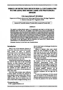
design limitations and to make a product that could be reproduced by other clinicians and amputees easily and relatively inexpensively. This article presents the results of the motion analysis study and describes the new design. MOTION ANALYSIS STUDY One male above-elbow amputee (43 years old, 80.7 kg, 174.8 cm; right arm amputation) performing a push-up using the original push-up device was compared with one nonamputee control participant (26 years old, 104.3 kg, 187.9 cm) performing a regular push-up. Each participant was asked to perform three sets of three consecutive push-ups, while an eight-camera Vicon (OMG plc, Oxford, UK) motion analysis system tracked the position of passive reflective markers placed at known landmarks on the upper body. The marker set included 13 markers for the amputee participant and 16 markers for the control participant. Two Advanced Medical Technology, Inc. (AMTI of Watertown, MA, USA) force plates recorded ground reaction forces of the upper body. Left elbow angle, right shoulder angle, torso tilt, and upper body weight distribution were calculated. A picture of the original push-up device used by the amputee participant is shown in Figure 1A. The muscular physique of the amputee participant is shown in Figure 1B, who regularly uses the device, performing 300 push-ups 5 days a week. The control participant exercises regularly by strength training four times a week at the university gym with free weights.
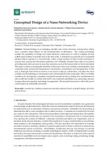
MOTION ANALYSIS RESULTS Both participants were able to perform push-ups without difficulty. The results show that the amputee tended to have an increase in torso tilt and weight distribution onto their nonamputated side, whereas the control participant stayed more level and centered, indicated by the amount of torso tilt and weight distribution, respectively (Fig. 2). Torso tilt in the positive direction indicates tilting onto the left side according to the segment definitions. Weight distribution is described as positive when more weight is on the right side and negative when more weight is on the left side. These results could be due to the decreased range of shoulder motion on the amputated side. The way the sling was rigidly attached to the frame may have affected the range of motion of the shoulder. Shoulder angle of the amputated side relative to the sound side looks similar to the comparison of the shoulder angles of the amputee and control participant in Figure 2. Although the range of shoulder motion is less for the amputated than the sound side, the residual limb is supporting body weight, and the benefits of the push-up exercise may still be experienced. REDESIGN OF THE PUSH-UP DEVICE The authors and amputee participant are disseminating these outcomes with hope that other trans humeral amputees will benefit from this device. Modifications were made by the authors following certain design criteria to make the device more
Figure 1. (A) The original push-up device used by the amputee participant. (B) The muscular physique of the amputee.
PUSH-UP DEVICE FOR ABOVE-ELBOW AMPUTEES
299
Figure 2. Graphs of left elbow flexion, amount of torso tilt, shoulder angle, and weight distribution during push-up cycles for the amputee and the control subject.
durable and user-friendly. The authors decided that the redesigned device should be easy to construct, made from common materials using common tools, lightweight, adjustable, durable, smaller than the original device, could be operated with one hand, and inexpensive. Dialogue with the amputee participant highlighted that sliding of the device across the floor should be minimized for push-up fidelity. Following these guidelines would allow the device to be constructed and used by many. Based on these guidelines, 1-inch polyvinyl chloride (PVC) was selected for the frame material. Ninety-degree PVC elbows (eight in total) and PVC T-joints (six in total) were the only connection pieces needed. These connectors can be found at most local hardware stores. The pieces and joints were connected
as shown in Figure 3. The PVC pipe was cut to the dimensions indicated in Figure 3. The angle of the three vertical pieces to the normal vertical direction was 15°. This angle was chosen because it was not too steep to cause a loss of vertical stability and also created a wide enough base of support to provide lateral stability. PVC cement was placed in the joints to provide security and added stiffness. Additional PVC piping placed in the front of the device increased the base and provided stability against rocking of the device. Rubber material was added to the bottom of the PVC frame to increase friction with any ground surface and limit lateral movement of the device across the ground during weight bearing. The most challenging design aspect was getting the sling to be functional. A pair of adjustable straps
300
WERNKE ET AL.
Figure 3. Connection of the pieces and joints with PVC pipe dimensions for the push-up device.
was used for the sling. These adjustable straps are made for hanging abdominal exercises and can be purchased at a number of stores. The level of the sling can be raised or lowered on the device by adjusting the Velcro arms of the straps to create a tighter or looser fit, allowing users of various heights and limb lengths to use the device comfortably. The straps are sewn together with a curve in the seam to form the sling and easily strap over the top portion of the device. Sewing them together creates a larger area for the residual limb to rest upon, and the curved seam forms a pocket for the residual limb. It is not functionally viable to just hang the sling over the top portion of the PVC because sliding of the sling across the PVC makes the push-up movement difficult. The solution to this problem was to cut two 3-inch sections of 1 1/2-inch PVC to be used as clamps. A longitudinal section of this PVC was removed to make a “C” shape. Clamping the sling to the 18-inch sections of PVC at the top of the device provides a secure connection and limits sliding of the sling. While the clamps held the straps in the same position, bunching of the loose part of the sling still occurred initially. To counter this problem, 6 inches from the Velcro arms of the straps were cut off and sewn onto the front of the sling at approximately a 45° angle. These straps were attached to an adhesive Velcro square placed on the front of the frame.
CONCLUSIONS The performance of a home-made push-up device for above-elbow amputees was analyzed, and a new design for the device was presented. The device allows for the suspension of the residual limb in order to perform a push-up comparable with that of nonamputees. While some kinematic outcomes of the amputee participant are not highly similar comparisons with those of the nonamputee participant, the authors feel that the benefit of the push-up exercise is still experienced. Pectoral development of the amputee through the continued used of this device is evidence of that. It is the hope of the authors and the amputee who originally designed the device that others will construct this device and benefit from its use. Future work will incorporate electromyography of the pectoral and shoulder muscles to analyze the level of muscle activity. ACKNOWLEDGMENT: The authors declare no conflicts of interest.
REFERENCES 1. Tatar, Y. Body image and its relationship with exercise and sports in Turkish lower-limb amputees who use prosthesis. Sci. Spor. 25(6):312–317; 2010. 2. TRS, Inc. Complete Product Listing. Retrieved February 2013 from http://www.oandp.com/products/trs/products. 3. Webster, J. B. Sports and recreation for persons with limb deficiency. Arch. Phys. Med. Rehabil. 82(3):S38–S44; 2001.