VOL. 11, NO. 21, NOVEMBER 2016
ISSN 1819-6608
ARPN Journal of Engineering and Applied Sciences ©2006-2016 Asian Research Publishing Network (ARPN). All rights reserved.
www.arpnjournals.com
DESIGN AND TESTING OF USER-CONFIGURABLE DRIVING BOARDS OF PULSED XENON LAMPS WITH ADJUSTABLE FLASH DURATION AND BRIGHTNESS FOR CARBON-NANOTUBES PHOTO-INDUCED IGNITION Patrizio Primiceri, Paolo Visconti, Daniele Longo, Raffaele Tramis and Antonio Paolo Carlucci Department of Innovation Engineering, University of Salento, Street for Monteroni, Lecce, Italy E-Mail :
[email protected]
ABSTRACT This paper describes the design and testing of programmable driving boards for turning on Xenon flash lamps, with the aim to photo-ignite Multi-wall carbon nanotubes (MWCNT) with added metal impurities (ferrocene), makers of photo-ignition process. The realized ac powered electronic boards present different features such as variable flash brightness, pulse duration and high flash rate as function of user-adjustable potentiometers or by PC provided command signals. By using the designed PC-configurable boards in the realized experimental setup, the lighting parameters (i.e. pulse energy/power and energy density) for different Xe lamps have been measured and optimized. Varying temporal/luminous parameters of used light sources by means of realized driving boards, different pulse energy and power values were obtained, in order to fully exploit and analyze MWCNTs/ferrocene photo-induced ignition. Finally, employing these boards, the ignition of MWCNT/Ferrocene mixtures has been triggered and investigated. Keywords: electronic driving boards, xenon flash lamp, carbon nanotubes photo-ignition, IGBT driver.
1. INTRODUCTION The photo-ignition process of CNTs was observed for the first time accidentally, exposing single wall CNTs to the flash of an ordinary camera (Ajayan et al., 2002). It was found that this photo-effect occurs in air for different types of SWCNTs, prepared with different methodologies and with different percentages of CNTs with respect to the metal catalyst (Fe) contained in them (from 50% to 90%) (Ajayan et al., 2007) (Braidyet. al., 2002) (Tseng et al., 2007) (Sysoevet al., 2011). The effects of features owned by used triggering Xe light source such as wavelength range selected by suitable optical filters, pulse duration and needed light pulse energy/intensity have been only partially analyzed, finding that a lower pulse energy is needed to trigger the ignition when a shorter flash duration is used (A. Badakhshanet al., 2014) (B. Chehroudi, 2012). In this context, aim of this work is to design and test different programmable driving boards with the purpose to trigger photo-ignition of CNT enriched with metal impurities by means of Xenon light pulse with proper adjustable parameters. The realized PC-controlled boards are used to obtain a Xenon light pulse with adjustable features, such as variable flash rate (up to 10Hz), pulse time duration (from 115µs up to 2.41ms) and pulse’s energy/intensity. These features can be varied manually by means of potentiometers located on board or interfacing the board with a PC. Finally, varying Xenon light source’s parameters, the photo-induced ignition of MWCNTs/ ferrocene mixtures was triggered; captured frames of the combustion process show the evolution over time of the ignition phenomenon.
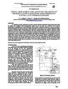
2. CIRCUITAL SCHEMATIC AND OPERATION OF DRIVING BOARD WITH ADJUSTABLE FLASH RATE AND LIGHT PULSE INTENSITY The circuital solution, shown in figure 1, powered by ac mains voltage (VRMS=230V), does not need a storage capacitor; in fact, the ac input sinusoidal voltage, after being elevated by means of an appropriate circuital solution, is directly applied on the flash lamp. Driving board’s features are adjustable intensity/power and flash rate (up to 10Hz) of light pulse by varying proper variable resistors. Utilizing a square wave with variable frequency [1 ÷ 10]Hz, it is possible to provide the trigger signal thus obtaining the light pulse. The square wave is generated by “variable frequency square wave generator” section, highlighted in green colour in figure 1; it can be also provided by 6.35mm external jack isolating automatically, in this way, the trigger control from “flash rate resistor”. Voltage elevator section (highlighted in red) allows to obtain, as previously cited, an elevation of ac input sinusoidal voltage in order to apply, on the flash lamp, a sine-wave signal whose voltage range is [325 ÷ 975]V and therefore to have the possibility to use lamps which provide higher luminous energy.
12336
VOL. 11, NO. 21, NOVEMBER 2016
ISSN 1819-6608
ARPN Journal of Engineering and Applied Sciences ©2006-2016 Asian Research Publishing Network (ARPN). All rights reserved.
www.arpnjournals.com The circuital section highlighted in purple provides a pulsed signal to set input of the latch suitable to generate the trigger signal, and regulates, by means of the “brightness regulator resistor” RINT (RPEAK in series with potentiometer in red rectangle), the luminous intensity/power of flash lamp. Intensity regulation is obtained through a RC circuit and a logical NOT gate. The NOT threshold levels are VIHmin = 2/3VZ and VILmax = 1/3VZ (where VZ is the voltage value, 12V, fixed by Zener diode in red circle). The operation circuit is the following:
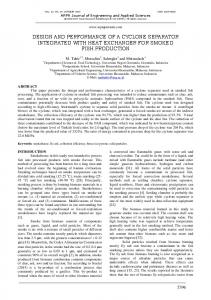
Figure-1. Circuital scheme of ac-powered designed board for driving Xenon flash lamps with variable flash rate and lamp brightness without a storage capacitor. The voltage elevator section can be modified in order to get two different voltage ranges of the sinusoidal signal applied on flash lamp ([325 ÷ 975]V or [0 ÷ 650]V). In Figure-2, two different circuital topologies, to perform a double voltage shifter (topology highlighted in red in Figure-2a) or a single voltage shifter, are shown.
(a)
(b) Figure-2. Voltage elevator section: double voltage shifter, on the left side, which performs an elevation of the ac input sinusoidal voltage in the range [325 ÷ 975]V and single voltage shifter, on the right side, that provides an elevation of the input signal in the range [0 ÷ 650]V (a). Graph with the sine-wave signals obtained by using the two different circuital topologies: input sinusoidal voltage with peak voltage value VP = 325V (blue curve), single voltage shifter with peak value equal to 2VP (green curve) and double voltage shifter with peak value equal to 3VP (red curve).
During the positive values of the ac input signal, the diode D1 is reverse biased and the capacitor C1 is charged through the resistor RINT, to 12V according to the time constant τ = RINT C1 (blue path in figure 1). When node A reaches VIHmin , the output of the NOT gate commutes, bringing its output voltage to 0V (node B) producing, in this way, on node C (the latch input), for a very short time, a negative spike. This negative spike and so trigger pulse that enables the flash, occurr after a time interval Δt (trigger delay time) that depends on time constant τ = RINT ∙ C1. In this way, by changing the resistor RINT, it is possible to delay (or anticipate) the instant (and thus the voltage value to apply for the light pulse) in which the discharge phase through the lamp, once the trigger signal is provided, starts. The negative spike is always synchronized with the ac 50Hz power voltage for two reasons: 1) the instant in which C1 starts charging is exactly when the ac sinusoidal input becomes positive; 2) from this moment on, the time needed to the RC circuit to charge C1 up to the value VIHmin is fixed by RINT. During the negative values of the ac input signal, voltage on node D drops down to a low value close to 0V, causing the discharging of the capacity C1 through the resistor R1 (green path in figure 1). Consequently, once the voltage on node A drops down to VILmax, the NOT gate commutes again towards VZ, causing a positive spike on node C but totally irrelevant. The trigger signal generator section is highlighted in blue; the negative spike signal is applied on the SET input of latch and a square wave on CLEAR input. The high level of square wave, this last provided by the square wave generator section or by external jack if connected, determines on inverted latch output, when negative spike on SET input occurs, a low pulsed signal that enables the pnp BJT (for Xenon lamp triggering). The block highlighted in orange is responsible for providing the trigger signal in order to ionize the gas inside the lamp. When the trigger signal occurs, the trigger capacitor discharges on the primary of the transformer (trigger coil), producing on the secondary of transformer a high pulsed voltage value of the order of kV; in this way, a strong ionization of gas contained in the Xenon lamp is obtained.
12337
VOL. 11, NO. 21, NOVEMBER 2016
ISSN 1819-6608
ARPN Journal of Engineering and Applied Sciences ©2006-2016 Asian Research Publishing Network (ARPN). All rights reserved.
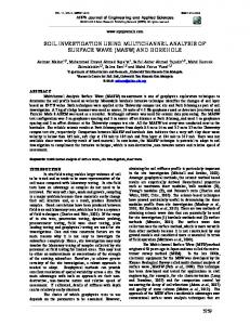
www.arpnjournals.com In Figure-3, the realized board is shown with properly indicated the different circuital sections.
Figure-3. Image of the realized driving board, connected to PC, with indication of the different circuital sections. The realized driving board can be used to drive different types of lamps adopting the following changes/ adjustments (performed on board by means of jumpers): the already discussed single or double level shifter and RPEAK value that determines the minimum possible trigger delay (when the potentiometer value is equal to 0 Ω) capturing in this way different values of ac voltage applied on flash lamp. RPEAK resistor can be changed to obtain different maximum power values of driving board (R PEAK = 43kΩ for piloting 1500W Xe lamps or 72kΩ for 750W power Xe lamps). Finally the C6 capacitor value (0.22µF) can be replaced with a different capacity (in our case 47μF), in order to modify slightly the luminous energy emitted by Xenon lamps. The curves reported in Figure-4 clarify the energies involved during the light pulse generation. The ac input sinusoidal voltage with single voltage shifter (vin + Vp, red curve) is applied on the flash lamp; when trigger occurs, C6 capacitor (charged to voltage value Vp) is quickly discharged over the lamp, until reaching the voltage value vin (orange curve). The total energy is obtained as sum of the stored energy contribution of C6 equal to ½(C6 Vp2), shown in green in Figure-4, and energy provided from vin (shown in blue). For potentiometer values higher than 18 kΩ (i.e. RINT ≥ 90 kΩ for RPEAK = 72kΩ), the vin captured value is already below the lamp’s threshold value (approximately 100V). Therefore in this case, the energy supplied to the lamp is given by the only contribution of the energy stored on C6; for C6 = 0.22µF, this contribution is practically negligible, whereas for C6 = 47µF this energy contribution is significant.
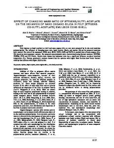
Figure-4. Analysis of involved energies using two different capacity values for C6 (0.22µF and 47µF), varying the potentiometer value. Stored energy on C6 does not concur to total energy if C6 = 0.22µF being its contribution negligible. On the contrary, when C6 =47µF, related stored energy is significant especially for potentiometer values higher than 18kΩ.Orange curve is ac input sinusoidal voltage (vin) and red curve the ac input sinusoidal voltage elevated by single shifter (vin + Vp). By means of Thorlabs optical power/energy meter and a pyroelectric sensor (ES145C model), the luminous energy emitted from 120J Xe flash lampwas measured varying the brightness regulator resistor value RINT. The experimental tests were performed using two C6 capacitor values (0.22µF and 47µF) and the obtained results are shown in Figure-5.
Figure-5. Luminous energy (mJ) and density (mJ/cm2) as function of RINT resistor for different values of capacitor C6, using the 120J Xe flash lamp.
12338
VOL. 11, NO. 21, NOVEMBER 2016
ISSN 1819-6608
ARPN Journal of Engineering and Applied Sciences ©2006-2016 Asian Research Publishing Network (ARPN). All rights reserved.
www.arpnjournals.com As reported in Figure-5, the red graph, relative to 120J Xe lamp and C6= 47µF, shows a higher energy than the blue curve obtained by using the same lamp but C6 = 0.22µF. For lower values of the potentiometer, the contribution of stored energy on C6= 47µF to the total luminous energy, as shown in Figure-4, is more significant respect to the negligible energy value related to C6 = 0.22µF; instead for RINT ≥ 18kΩ, the luminous energy is not zero only for C6= 47µF due to the stored energy on C6 capacitor itself. 3. CIRCUITAL SCHEMATIC AND OPERATION OF AC-POWERED DRIVING BOARD WITH ADJUSTABLE LIGHT PULSE TIME DURATION BY USING IGBT SWITCH The designed driving board is useful when shorter lighting pulses with respect to storage capacitor’s discharge time are needed. In a typical flash-lamp at triggering instant, the stored charge on COUT capacitor fully discharges through the lamp, producing the light flash. In order to vary the flash time duration producing shorter light pulses, the adopted circuital solution uses a device that stops the current flow in the discharging path before the discharge phase ends. This goal is obtained by using a IGBT switch that, located in series to flash lamp, is able to control the light pulse duration opening the current path before that COUT discharge is completed. Also the IGBT device controls trigger pulse required to ionize the Xenon gas inside the flash lamp. The circuital solution is powered by the ac mains voltage (VRMS=320-330V); therefore it needs just a simple rectifier to produce proper voltage that will be provided to the COUT storage capacitor. The IGBT-based architecture allows to adjust the flash time duration between 115µs and 2.41ms by means of flash time regulatorpotentiometer orPC-provided control signal. A storage capacitor COUT with selectable value of 141µF (3x47µF) or 330µF (7x47µF) can be utilized (as shown in prototype board of Figure-9). 230VRMS power input voltage is used to charge the storage capacitor whereas a DC voltage VIN (from 5V to 15V) is needed to supply the IC NE555 timer. The designed circuital scheme of the ac powered driving board which employs the IGBT switch (red circle) is reported in Figure-6. The photoflash capacitor COUT is charged at Vpeak level equal to 0V M × √ .Furthermore, this circuital typology needs an independent IGBT driver, which block diagram is shown in figure 7, to provide the proper signal at the IGBT gate. The IC IRS4427 driver can supply an output voltage from 6V to 20V. It’s composed by a CMOS trigger Schmitt input stage, a pre-driver unit needed to rise the incoming low-voltage signal and the final stage for driving the gates of Q1 and Q2 MOSFET transistors, as shown in Figure-7.
Figure-6. Circuital scheme of IGBT-based designed board.
Figure-7. Block diagram of used IGBT driver IRS4427. A fundamental block is the timing circuit based on IC NE555 timer. This latter is used in monostable configuration in order to produce a high logic signal (5V) of the desired time duration. The time duration of output high pulse can be lengthened or shortened as function of the specific application by adjusting RTOT (sum of R and flash time regulatorpotentiometer RPOT). NE555 input signal is normally high and output signal normally low; when a small negative pulse (lower than VCC/3) is applied to the input, the output goes high with a pulse width T, the required time to charge C to (2/3)VCC, given by: T=ln3∙RC=1.1∙RC Based on this formula, RTOT (sum of R = 1kΩ and RPOT = 20kΩ) and C (100nF) values are chosen obtaining a flash time duration from 115µs (RPOT = 0Ω) up to 2.41ms (RPOT = 20kΩ), as function of RPOT value. These durations are calculated in order to be shorter than the free capacitor discharge usually in the range [2÷10]ms depending on the COUT storage capacitor value. In the monostable configuration, the negative trigger pulse applied to NE555 input has to be shorter than desired time duration of NE555 output pulse. This means that a negative input pulse shorter than minimum output
12339
VOL. 11, NO. 21, NOVEMBER 2016
ISSN 1819-6608
ARPN Journal of Engineering and Applied Sciences ©2006-2016 Asian Research Publishing Network (ARPN). All rights reserved.
www.arpnjournals.com duration (115µs) is needed; this is obtained by using the following circuital solution of Figure-8. Furthermore a protection diode D1 has been used to remove potentially dangerous positive spikes, otherwise created when positive going transition of input pulse occurs.
pulse time duration, the final voltage on C OUT storage capacitor, before that IGBT turns off, is greater if higher COUT value is used due to slower discharging. In order to perform the experimental tests in the right way, it’s important to measure the ac mains voltage applied to the realized driving board since the voltage value stored on the photoflash capacitor COUT depends on it. The measured voltage value is 226VRMS providing a rectified voltage (measured) equal to 315V on the storage capacitor. The graph of the luminous energy values obtained by using COUT = 330µF (red curve in figure 10) becomes flat when the pulse temporal length is higher than 690µs (RPOT = 5kΩ, overall resistor RTOT = 6kΩ), while using COUT = 141µF, this behaviour can be observed for pulse time durations higher than 350µs (RPOT = 2kΩ, overall resistor RTOT = 3kΩ), as shown in the blue curve of Figure-10.
Figure-8. Circuital solution to produce a negative input spike (shorter than 115µs) to obtain output triggering signal with proper time duration setted by RTOT and C values. Following the realized driving board is reported in Figure-9 with the different circuital sections highlighted; on the board, three IGBT switches were mounted to support the very high current value that flows during discharge phase in the flash lamp and IGBT devices connected in series.
Figure-10.Luminous energy (mJ) and density (mJ/cm2) as function of pulse time duration in the range [115÷2415]µs (depending on variable resistor), using a 50J Xe lamp at 10mm from sensor with storage capacitor equal to 141µF and 330µF. The following table and graph (Figures 11 and 12) show the different luminous energies, for two distance values (10mm and 4mm) between the pyroelectric sensor and the used 50J Xe lamp, measured using COUT = 141µF. As reported in Figure-12, the luminous energy is lower if the distance lamp-sensor is 10mm respect to 4mm. Figure-9. Image of the ac powered IGBT-based driving board with pointed out the different circuital sections; the storage capacitor is charged by a voltage rectifier (diode bridge in the red circle). The luminous energy, emitted employing the Xe flash lamp (50J Xe lamp model) was measured using COUT = 141µF and afterwards COUT = 330µF. Utilizing the greater COUT value, the whole discharging time is about twice respect to lower COUT value; similarly, for same
12340
VOL. 11, NO. 21, NOVEMBER 2016
ISSN 1819-6608
ARPN Journal of Engineering and Applied Sciences ©2006-2016 Asian Research Publishing Network (ARPN). All rights reserved.
www.arpnjournals.com photo-ignition process (Chehroudiet al., 2008) (Badakhshan et al., 2012). In the photo-ignition test, the realized driving board without a storage capacitor was employed adopting the following settings: single voltage shifter, C 6 = 0.22µF and RPEAK (in series with the brightness regulator resistor) equal to 72kΩ. In order to provide to the driving board a single pulse on demand, a comparator PC-interfacing board and a LabVIEW application, suitably developed, were used. The realized experimental setup is shown in Figure-13.
Figure-11. Luminous energy, density and calculated power by using IGBT-based board with COUT=141µF, 50J Xe lamp, 10mm and 4mm distances between light source and pyroelectric sensor, varying flash time duration.
Figure-13.Experimental setup used to perform the photoignition of MWCNTs/ferrocene mixture.
Figure-12. Luminous energy (mJ) and density (mJ/cm2) as function of pulse time duration in the range [115÷2415]µs using 50J Xe lamp at 10mm or 4mm from light sensor (COUT=141µF). 4. MWCNTS/FE PHOTO-IGNITION EXPERIMENTAL TESTS BY USING REALIZED ELECTRONIC DRIVING BOARDS The carried out experimental tests concerned the photo-induced ignition of MWCNTs/ferrocene mixtures with 75% of ferrocene by weight varying the energy of Xe luminous pulse incident on sample. The weight ratio percentage was chosen according to already published results in which a greater amount of Fe respect to CNTs results in a lower luminous energy required to trigger the
The used driving board was triggered by a 5V pulsed signal provided by PC through the realized interfacing board. The sample was placed 4mm far from the Xenon flash-lamp. The luminous energy emitted by the 50J Xe flash lamp was measured with a distance lamp-sensor of 4mm and then, each time, the pyroelectric sensor was replaced with the MWCNTs/ferrocene mixture preserving the same distance lamp-sample, to perform the ignition test (as shown in Figure-14).
Figure-14.Xe lamp on the sensor at the distance of 4mm to measure the luminous energy (a) and Xe lamp on the mixture at the same distance (4mm). Changing RINT, through the potentiometer relative to intensity brightness control (see Figures 1 and 3), we
12341
VOL. 11, NO. 21, NOVEMBER 2016
ISSN 1819-6608
ARPN Journal of Engineering and Applied Sciences ©2006-2016 Asian Research Publishing Network (ARPN). All rights reserved.
www.arpnjournals.com modified the energy emitted by the lamp starting with the lower energy, first delivered on the sensor and then on the mixture, piloting a single pulse by PC. In this way, we increased the pulse energy until the ignition phenomenon was observed, repleacing the mixture not ignited, each time, with a new one. In the following frames, the evolution over time of the combustion process is shown with indication of the time intervals during the combustion itself.
on sampleobtaining in this way the combustion trigger and the minimum energy at which it occurs. Frames of the combustion process were taken during the ignition phenomenon highlighting that the photo-ignition occurs soon after the light pulse and continues for about one or few seconds affecting the entire mixture sample. REFERENCES P. M. Ajayan, M. Terrone, A. de la Guardia. 2002. Nanotubes in a flash-ignition.Science. 296: 705. P. M. Ajayan, R. Ganapathiraman, A. de la Guardia. 2007. Method of transforming carbon nanotubes. Patent US 7,217,404 B2 (May. 15). N. Braidy, G. A. Botton, A. Adronov. 2002. Oxidation of Fe nanoparticles embedded in single-walled carbon nanotubes by exposure to a bright flash of while light.Nanoletters. 2(11): 1277-1280. S. Tseng, N. Tai, W. Hsu, L. Chen, J. Wang, C. Chiu, C. Lee, L. Chou, K. Leou. 2007. Ignition of carbon nanotubes using a photoflash. Carbon. 45: 958-964. N. N. Sysoev, A. I. Osipov, A. V. Uvarov, O. A. Kosichkin. 2011. Flash ignition of a carbon nanotube. Moscow University Physics Bulletin. 66(5): 492-494.
Figure-15. Frames of combustion process taken during ignition phenomenon. It is clearly visible in the fourth frame (at 66.66 ms), soon after the light pulse, the ignition of the MWCNTs/ferrocene mixture triggered by the Xe lamp which appears still in orange colour. The photo-induced ignition was obtained by irradiating the sample with a measured luminous energy density equal or greater than about 85mJ/cm2. 5. CONCLUSIONS In this research work, different programmable driving boards were designed, realized and tested to obtain a Xenon light pulse with different characteristics in order to photo-ignite MWCNTs/ferrocene mixture by varying the Xe light source’s parameters. Each driving board presents different features such as variable flash rate, pulse’s energy/intensity and time duration adjustable by user through potentiometers located on the electronic boards. The triggering signal can be provided manually through a push-button placed on boards, or by a LabVIEW application installed on PC and a PC-interfacing board to provide the single triggering pulse on demand. The realized boards were employed to perform the photo-induced ignition tests of MWCNTs/ferrocene mixture varying the energy of Xe luminous pulse incident
A. Badakhshan, S. Danczyk. 2014. Ignition of Nanoparticles by a Compact Camera Flash. Air Force Research Laboratory (AFMC), AFRL-RQ-ED-TR-20140029. B. Chehroudi. 2012. Minimum ignition energy of the light-activated ignition of single-walled carbon nanotubes (SWCNTs). Combustion and Flame. 159: 753-756. B. Chehroudi, A. Badakhshan, S. Danczyk, C. Morgan. 2008. Ignition Characteristics of Single Walled Carbon Nanotubes (SWCNTs) Utilizing a Camera Flash for Distributed Ignition of Liquid Sprays (Preprint). Air Force Research Laboratory (AFMC), AFRL-RZ-ED-TP-2008423. A. Badakhshan, S. Danczyk. 2012. Photo-ignition of Carbon Nanotube for Ignition of Liquid Fuel Spray and Solid Fuel. TMS 2012, 141st Annual Meeting, Orlando, FL.
12342