Chris Conger, Ann Gordon-Ross, and Alan D. George. NSF Center for ...... 8. References. [1] C. Carmichael, M. Caffrey, and A. Salazar, âCorrecting Single-Event.
Design Framework for Partial Run-Time FPGA Reconfiguration Chris Conger, Ann Gordon-Ross, and Alan D. George NSF Center for High-Performance Reconfigurable Computing (CHREC) ECE Department, University of Florida, Gainesville, Florida 32611 Email: {conger, ann, george}@chrec.org Abstract
be corrected and re-written to configuration memory without having to halt and configure the entire device [1]. Despite these advantages, significant commercial interest in PR has yet to materialize due mainly to merciless design flows and a lack of supporting software tools. Xilinx is currently the only major FPGA vendor to offer support for PR in their programmable logic devices. PR design adds a layer of complexity to system design, requiring system designers to use architectural knowledge of the target device and manually floorplan (determine reconfigurable regions) a significant portion of their design. Designers must: (1) logically partition their HDL design into nonoverlapping partially-reconfigurable modules (PRMs), (2) define the physical size, shape, and placement of partially-reconfigurable regions (PRRs), (3) determine the mapping of PRMs to available PRRs, and (4) provide proper communication between PRMs. Currently, system designers have little guidance for these steps, and the lack of abstraction from these low-level details likely discourages PR use. To compound the lack of design flow support, requirements and restrictions on PRRs severely constrained earlier Xilinx devices [2], up to and including the Virtex-II Pro family. For example, early devices restricted PRRs to entire columns of the FPGAs restricting placement and sizing of PRRs. Also, under older tool flows, passing static signals through a PRR posed a serious practical challenge. As a result, it was difficult to avoid module isolation (modules unable to communicate with other modules or pins) if they resided on opposite sides of a PRR. Ultimately, these constraints made PR design with older FPGA devices difficult to incorporate into a wide variety of applications. However, with the relatively recent release of the Virtex-4 and Virtex-5 series of FPGAs [2], PR design constraints are significantly relaxed. For example, flexible-sized PRRs in a tilebased frame architecture replace the large, inflexible column-based PRRs. Static signals are now permitted to pass freely through PRRs, and will not glitch during reconfiguration. Additionally, Xilinx offers a simplified PR design flow within their standard FPGA development environment [3], which helps to automate some of the previous burdensome requirements. Nevertheless, even with these advances, PR design is still a challenging and specialized task. Even with little design and tool support, the research community recognizes the powerful potential of the fine reconfiguration granularity realized by PR, and a variety of conceptual approaches have been developed to incorporate PR into embedded systems using Xilinx FPGAs [4-10]. Unfortunately, due to the relatively recent unveiling of Xilinx’s new PR design flow, these works largely lack applicability to state-of-the-art PR tools and platforms. As a result, there exists a vacuum in academic research and experimental results exploring PR systems using the latest Virtex FPGAs. In this paper, we define design methodologies and “best practices” to incorporate dynamic runtime PR into reconfigurable computing (RC) systems based upon the Virtex-4 and Virtex-5 devices. We propose these design methodologies and frameworks
Partial reconfiguration (PR) reveals many opportunities for integration into FPGA design for potential system optimizations such as reduced area, increased performance, and increased functionality. Even though recent advances in Xilinx’s Virtex-4 and Virtex-5 FPGA devices and design tools significantly improve the practicality of incorporating PR, unfortunately, system designers largely lack sufficient guidance to design these systems. Efficient system design exploration and extensive manual floorplanning is required to fully enhance the capabilities of a system and/or optimize metrics such as power consumption, device quantity and size, designer productivity, and design re-use. To fully leverage PR, system designers must acquire a strong knowledge of the PR design flow as well as the low-level architectural details of their target device. In this paper, we propose design methodologies to assist designers in efficient PR system design and define frameworks to enable rapid system prototyping, enabling designers to harness the capabilities of PR without having to deal with many of the intricate details. Furthermore, we identify new opportunities for optimization, which are only made possible with the tile-based layout of the Virtex-4 and Virtex-5 FPGAs.
1. Introduction SRAM-based FPGAs are reprogrammable hardware devices that enable modification to their hardware architecture easily and dynamically during runtime. Whereas this reconfiguration allows changes to functionality, one potential drawback is that even small changes require updating the entire FPGA fabric, potentially disrupting system execution, as the entire system may need to stall during reconfiguration and system reset. Given the increasing size of FPGA fabrics, this reconfiguration time can be prohibitive as bitstream sizes (data needed to reconfigure the fabric) increase. Furthermore, if many different FPGA configurations are required, a prohibitive amount of memory may be needed to store all the bitstreams. Dynamic partial reconfiguration (PR) enhances FPGA systems by partitioning the fabric into numerous reconfigurable regions, and allowing these regions to be independently reconfigured during runtime. By reconfiguring only the region of the fabric that requires modification, the remainder of the fabric (the regions not being reconfigured) continues execution without disruption. Since PR regions may be much smaller than the entire fabric, PR can result in reductions in reconfiguration time, bitstream communication, and storage memory. In systems where all functionality need not be present in the FPGA concurrently, the system can be decomposed into smaller functional units which collectively represent the entire system. PR enables a smaller FPGA to provide identical system functionality by loading/unloading these functional units from the PR regions on demand. In addition, PR makes it possible to correct errors in the FPGA’s configuration memory without interrupting device operation, by allowing individual corrupted configuration frames to
1
to ease PR development for system designers as well as application developers. Collectively, these techniques assist in producing both functionally correct and efficient systems and facilitate rapid system prototyping. Furthermore, we explore parameter tradeoffs for new optimizations made possible by the tile-based layout, and identify these parameters for design space exploration.
optimizing spare region allocation to minimize wasted resources and impact on system performance during normal operation. The vast majority of previous research in PR has focused on describing and analyzing specific architectures or designs, specific capabilities or mechanisms made possible via PR, or circumventing challenges of designing for early Xilinx devices. However, an important note is the lack of, value, and need for design flow support, to help insulate the designer from the low-level details of PR design and assist in optimization of FPGA architectures for PR.
2. Related Work Early PR work used the column-based layout of the Virtex-II FPGAs [4-8]. Ullmann et al. [4] proposed a PR architecture for automotive systems including a MicroBlaze soft-core processor, an internal configuration access port (ICAP) controller, and four userdefinable PRRs. They discussed run-time resource management and preservation of state information when swapping PRMs. A follow-up paper [5] explored the same PR architecture in more detail, focusing on a novel slice-based “bus macro” component (discussed in Section 3.1). Original bus macros were based on tristate elements (TBUFs), which, if malfunctioning or used incorrectly, could cause a short circuit within the FPGA, potentially destroying the device. Xilinx has since eliminated TBUFs in Virtex-4 devices and beyond and instead incorporated slice-based bus macros. To alleviate the full-column reconfiguration requirement of Virtex-II FPGAs, previous work explored methods to partially reconfigure the columns. Hubner et al. [6] proposed a complex technique that required the user to perform a read-modify-write process on configuration memory using Xilinx’s JBits tool (as opposed to simply loading a new partial bitstream). While improving the flexibility of PR, a drawback to this approach was large reconfiguration times, on the order of seconds. Sedcole et al. [7] proposed a technique to address the difficulty in routing static lines through PR columns, using a read-modify-write approach to perform the reconfiguration, similar to that used in [6]. Wichman et al. [8] suggested that using external components to perform reconfiguration of an FPGA creates a single point of failure, and introduced the risk of losing the ability to reprogram the FPGA in the event of a failure of the reconfiguration controller. Because of this risk, they recommended using the ICAP as described in [4] for self-reconfiguration. PR can also be leveraged to improve the reliability and lifetime of FPGA devices, as described by Emmert et al. [9]. They proposed a mechanism called Self-Testing AReas (STARs), which continuously tests a device for permanent faults during operation, and reconfigure around failed areas. They extended this research in [10] by considering enhanced capabilities such as partial use of a faulty region, as well as
3. PR Overview Before introducing the proposed design flows for PR, it is worth reviewing the common terminology that is necessary to understand the discussions that follow. In this section, we define terminology and architectural features associated with PR, as well as metrics of interest when measuring or comparing architectures.
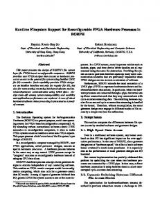
3.1 PR Architecture All PR designs are decomposed into two basic regions, the static region and the reconfigurable region. The static region, also referred to as the base region, contains all static logic (logic that never needs to be reconfigured), such as external memory controllers or network interfaces, embedded processor cores, and on-chip busses. The reconfigurable region can be dynamically reconfigured without disturbing the logic in the static region. This region can be further decomposed into as many independent PRRs as the designer wishes. It is left to the designer to determine the optimal partitioning of their design into the static region and one or more PRRs. The PRRs must be explicitly defined in terms of physical location, size, and shape, and the process of defining these parameters is referred to as floorplanning. The output of floorplanning is a set of constraints that define the physical layout of the design on a specific device, also referred to as an overlay. PRMs represent designer-identified application modules and are mapped to particular PRRs. PRMs are synthesized and placed and routed separately from the static region and other PRMs. PRRs may be time-multiplexed by multiple PRMs, where only one PRM may be present at a time, and the PRMs may be swapped in and out dynamically (n-to-1 mapping of PRMs to a PRR). All PRMs that share a given PRR must have identical port signal definitions, or input and output signals, so that they all appear to be the same module from the outside. To pass signals into and out of a PRR, Xilinx provides components referred to as bus macros, which serve as anchor points to ensure the physical location of the signal at the region interface never changes. Figure 1 shows the architecture for a generic System-on-Chip design, using an embedded PowerPC processor, on-chip bus, and a variety of standard as well as user-defined peripherals. All components except for the three user-defined peripheral components are located in the static region. Each of the three userdefined components represents a PRR. Note that the sizes represented in this layout are arbitrary and the PRRs could be much larger in relation to the static region. Using this partitioning, processor execution is not interrupted, the external memory controller remains active, and the network connection remains intact during reconfiguration of any of the PRRs. Custom hardware accelerators (e.g. floating-point units, FFT engines) or other mission-specific functions can be designed as PRMs, and loaded (i.e. configured) into one of the three PRRs. For this example architecture, communication with the PRMs occurs via the on-chip bus, which will typically have some standardized interface for peripherals. Having the interface signals pass through bus macros allows a PRM to interface with the on-
Off-chip connection
Static Region External DDR2 Controller
BRAM
Ethernet MAC
PPC (or MicroBlaze) Processor Local Bus (PLB) bridge On-chip Peripheral Bus (OPB)
User-defined peripheral #1
User-defined peripheral #2
User-defined peripheral #3
PRR #1
PRR #2
PRR #3
ICAP controller
Figure 1: Example FPGA architecture for PR. 2
this uncertainty, the PR design strategy for multipurpose systems is a stark contrast to special-purpose systems in that multipurpose system design focuses on maximizing flexibility and promoting design reuse. To measure and compare the quality of PR designs, we use the following three metrics: clock frequency, bitstream size, and internal fragmentation. Clock frequency is an important metric and is sensitive to PR-specific overheads such as manual floorplanning. Bitstream size affects reconfiguration latency as well as data storage requirements. Finally, internal fragmentation in PR design can become an issue as floorplanning is performed manually. Allocating PRRs of fixed sizes, which provide sufficient resources to each of the modules that will share a given PRR, can be challenging to achieve while minimizing the amount of wasted resources. Since resources allocated to a given PRR cannot be used by logic in any modules that do not occupy that region, the amount of resources that remain unused when defining PRRs is a metric of interest.
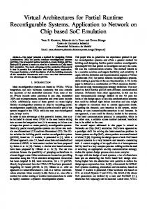
BRAM column
DSP column
Slice array
PR granularity in early Virtex PR granularity in Virtex-4 and Virtex-5
Figure 2: Illustration of typical FPGA layout. chip bus. Each bus macro allows four or eight signal bits to pass through, and only requires one or two slices, respectively. A slice can be thought of as the fundamental logic unit of the FPGA, and even simple designs can consume hundreds or thousands of slices. Thus, the resource overhead of bus macros is often negligible. Figure 2 shows a typical Xilinx FPGA layout, with columns of memories (BRAM) and hardware multipliers (DSPs) distributed throughout an array of slices. The internal configuration access port (ICAP) controller allows the FPGA to reconfigure itself through an internal configuration interface, without the need for external components (self-reconfiguration). Use of the ICAP implies PR, since some logic must remain active to control the ICAP itself. In this architecture, the ICAP controller is connected as a peripheral on the on-chip bus, so that self-reconfiguration can be controlled by software.
4. Proposed PR Design Flow Methodologies In this section, we propose two PR design flow methodologies, each of which is specifically tailored for its intended system type. These proposed methodologies are intended to help designers proceed through the PR design process in an organized manner, while taking advantage of opportunities to optimize the design or improve designer productivity.
4.1 Special-Purpose PR System Design From a designer’s point of view, special-purpose FPGA systems have the distinct advantage of containing all the information that is needed to create a tailored, highly optimized design implementation before system deployment. We divide the design flow for specialpurpose systems into three main stages: region partitioning, region sizing and placement, and implementation with timing verification. Figure 3 illustrates this process. After the system designer architects the system as a whole, the first stage in the special-purpose PR design flow that differentiates it from a normal, non-PR design flow is region partitioning. This stage consists of partitioning the FPGA fabric into two distinct regions: the static region and the reconfigurable region, the latter with as many PRRs as is required for the mission or application. Choosing the appropriate number of PRRs can be a difficult task, given that time-independent tasks can multiplex the hardware resources of a single PRR. For non-PR designs, all timeindependent tasks must coexist on the FPGA fabric, with idle tasks
3.2 System Classes and Metrics Before proposing or suggesting any particular PR design flow, it is important to define the type of system being designed to determine an appropriate system layout. Depending upon the intended usage of a system, system design flow will differ greatly. System designers demarcate system types based on whether or not all the PRMs will be defined prior to system implementation. In special-purpose system design, the system designer knows a priori every application that will execute on a particular system. In this system, the system designer employs special approaches in designing the PR system in order to optimize the physical mapping of static and reconfigurable modules. Additionally, since the system designer identifies all PRMs that will exist throughout the lifetime of the system, control-flow analysis determines all execution transitions that define which PRMs must co-exist on the FPGA fabric, and determines when each PRM must be loaded into its respective PRR (see Section 4.1 for further details), culminating in a highly specialized system design. However, it is often conceivable that the system may be designed with the intention to re-use it for multiple target applications in the future, or to upgrade components as improved versions emerge. Thus, a system designer would not have the advantage of knowing a priori all potential PRMs. In multipurpose system design, the system designer must allocate PRRs with fixed physical dimensions and locations, without knowing how application modules may be mapped to these regions. Interfaces between the PRRs and the static region of the system must also be fixed at design-time, further constraining the capability of the system to support arbitrary applications in the future. Because of
Region Sizing & Placement
Region Definition
Xilinx PR Implementation Flow
Design Profiling
full and partial bitstreams
Implementation w/ timing verification
Region Partitioning
Control Flow Graph + Synthesis Results
Overlay Generation
constraints file
Figure 3: PR design flow for special-purpose systems. 3
simply wasting resources and power. PR prevents those wastages by on-demand loading/unloading of the PRMs from shared PRRs, potentially resulting in lower power consumption, or the ability to use smaller and/or fewer FPGAs. However, in order to benefit from this PRR-multiplexing, a module mapping must exist that specifies which PRMs will share which PRRs. To assist in module mapping, a control-flow graph characterizes system execution. Nodes in this graph define both the execution states that the system transitions through during all phases of execution as well as the potential modules. Essentially, the control-flow graph depicts execution path coverage for the application. By identifying sets of mutually exclusive nodes (those that do not exist simultaneously over all states), the system designer can group nodes and allocate those nodes as modules in shared PRRs. Figure 4 shows an example of region partitioning. Region partitioning produces a set of PRRs, along with a mapping of a set of PRMs to each PRR. In the next stage, region sizing and placement, PRRs are mapped to specific locations within the FPGA fabric, in effect creating a template, or overlay, with holes or sockets for each PRR. Assigning PRMs to shared PRR sockets is much like fitting puzzle pieces into the FPGA fabric. Each PRR (hole in the puzzle) has one specific form, defined by the input/output ports (port interface) of the region. For a PRM (the puzzle piece) to fit into a PRR, the puzzle piece must match the puzzle piece hole – thus, all PRMs intended to share a PRR must have the same port interface. To comply, the system designer must create a wrapper module for each PRR, containing all input/output ports defined for that region. Each PRM is designed within the wrapper module of its corresponding PRR to ensure that the toplevel declaration of each PRM has the same port interface as every other PRM in that same region. Wrapper module generation is required and specific for each PRR. By synthesizing individual PRMs, the system designer determines the overall resource requirements of each PRR (see Figure 5). This resource knowledge is a critical advantage in special-purpose systems, as each PR socket in the overlay can be sized, shaped, and positioned to meet system optimization goals. At this point, the system designer is once again faced with a problem requiring a heuristic solution: how to best map PRRs to physical locations within the FPGA. One option is to use generic, pre-existing overlays, but doing so defeats the intention of having a special-purpose system. A better solution would be to algorithmically generate an overlay to match the needs of the
S3
S4
4.2 Multipurpose PR System Design System designers developing a multipurpose FPGA system do not have the advantage of knowing in advance all of the required PRMs, and thus must design a base system intended for a variety of usages. One possible usage would be as a general multipurpose platform available to application developers for use in product design. Application-specific modules, or updated versions of existing modules could be designed for this general-purpose platform in isolation from many of the PR-specific details. Figure 6 illustrates our proposed design flow for multipurpose PR systems. An important characteristic of multipurpose system design is the decomposition of the overall flow into two separate flows: (1) the architecture flow, and (2) the application flow. We propose the architecture flow for a PR system designer to produce a base multipurpose PR system, and the application flow for an application designer intending to use the system for product design. The first stage in multipurpose system design, region definition, is critical for both the architecture flow and the application flow. For the architecture flow, this stage defines the flexibility, efficiency, and reusability of a multipurpose PR system and hinges largely on planning effort and anticipation of future
Design decomposed into the following modules: {A, B, C, D, E, F, G}
S1
S2
specific design and then estimate the quality of this overlay by using a weighted sum of costs. Cost functions could include aspect ratio (geometry) of the PRR, amount of wasted resources, and position relative to needed input/output buffers (IOBs), routability, and others. The system designer, or better yet an automated tool, could then modify the overlay and re-evaluate the cost function for a number of iterations until an acceptable solution is found. After completing the region sizing and placement stage, the system designer will have a useable overlay to accompany the PRM mappings. The last stage in our proposed special-purpose design flow is to generate the partial bitstreams that represent each of the PRMs as well as full bitstreams to represent each of the states within the control-flow graph. The full bitstreams are necessary to ensure that each possible combination of PRMs satisfies the timing constraints of the system. The system designer must first generate a top-level wrapper to tie the design together, including a black-box instantiation for each individual PRR as well as the static region of the design and bus macros for communication. At this point, the manual portion of specialpurpose design is complete and the system designer invokes the Xilinx PR implementation flow to generate the full and partial bitstreams.
Slices
BRAMs
DSPs
A
5126
34
0
STATE
MODULES
B
332
2
0
S1
A, B, C
C
1105
8
0
S2
A, B, C, F
D
894
4
2
S3
A, B, C, G
E
780
4
2
S4
A, B, D
F
2441
16
8
S5
A, B, E
G
3087
16
8
Design partitioned as follows : STATIC: A, B
Since all modules are known, synthesis results yield the necessary information for design profiling
PRR_1: C, D, E S5
Module
PRR_2: F, G
Figure 4: Sample region partitioning of a PR design.
PRR_1 (shared by C, D, E): - slices = 1105 (C) - BRAMs = 8 (C) - DSPs = 2 (D/E) PRR_2 (shared by F, G): - slices = 3087 (G) - BRAMs = 16 (F/G) - DSPs = 8 (F/G) Total static resources (A/B): - slices = 5458 - BRAMs = 36 - DSPs = 0 Device Requirements: (static + PRR_1 + PRR_2) - slices = 9650 - BRAMs = 60 - DSPs = 10
Figure 5: Sample design profiling calculations.
4
Hardware Spec + Synthesis Results
Application Spec
Region Definition
Application Module Design
5. PR Design Framework Analysis
Overlay Generation
PR module template(s)
Synthesis
Xilinx PR Implementation Flow
Placed & routed static design
Xilinx PR Implementation Flow
full bitstream
design is synthesized and placed and routed, as all of the logic in the base design remains unchanged. This isolation of the application flow from the architecture flow of the design reduces synthesis and place and route tool execution times, which otherwise can be exceedingly high during the iterative development and testing stage of large, complex designs. The main feature of the two proposed design methodologies that separates them from traditional, non-PR design flows for FPGAs is the amount of floorplanning and formulation required before and during code development and synthesis. Even the particular way that some HDL files must be organized is specific to Xilinx’s current PR design flow, and may change in future tool releases. However, determining an optimal overlay for the design or platform will remain a critical component in PR design, and little to no guidance is offered for this performance-critical task. After deciding on an overlay, the remainder of the design process involves invoking various Xilinx implementation tools in a specific order, which is usually accomplished via custom scripts. In this section, we analyze aspects of our two tool-independent design methodologies with respect to overlay generation. We will focus on the affect that forcing modules into a particular geometry has on resulting clock frequency, bitstream size, and internal fragmentation of the design.
partial bitstreams
Architecture Flow
Application Flow
Figure 6: PR design flow for multipurpose systems. system usage. The ultimate goal of this stage is to decide on an overlay specification, and generate module templates for application designers. A system designer must consider two key issues during the region definition and overlay generation stages: (1) PRR shaping and placement, and (2) the port interface for each PRR. By defining a certain shape and size for each PRR, a system designer is effectively fixing the number of resources available to PRMs intended for that region. Also, since signals that will cross between PRRs must be fixed in the base system and connected to bus macros, the port interface on the PRRs cannot change. Once the system designer specifies the overlay, the architecture flow only needs to be performed once to generate the base bitstream. The only difference between the implementation stage of the architecture flow for a PR design and a non-PR design flow is the specific method for partitioning the top-level HDL design file [2], and the presence of bus macros. The output of the architecture flow is a full bitstream for the FPGA, which can be downloaded to the device at any time. The fully placed and routed design must also be archived for use when designing the PRMs for this system in the application flow. In order to permit static signals to pass through PRRs, and allow this to occur without effort from the application designer, the placed-and-routed static design is read during place and route for that PRM in order to route around any resources used for a static signal passing through the targeted region. At this point, an application designer can use the base system to implement a new application on this PR platform. The application designer is completely insulated from the low-level PR design details, involving PRR definition, overlay generation, as well as many other implementation details. The system designer provides with the platform an interface specification or template for each PRR in the design, which the application designer uses as a starting point for design entry of their particular PRM. During the application flow, only the logic for the particular PRM under
5.1 PRR Geometry With the elimination of the full-column PRR requirement in Virtex4 and Virtex-5 FPGAs, designers are presented with much more flexibility in the shaping and sizing of the PRRs. During overlay generation for both design flows, system designers are left with the task of determining the geometry (size and shape) of each PRR. This stage is important in order to minimize the amount of unused resources, as well as to avoid unintentionally decreasing the attainable clock frequency. Whereas determining the amount of resources contained within a given area of a device and balancing the resource requirements for a set of PRMs is straightforward, determining an optimal geometry is more difficult. There currently exists no good way to predict the impact that forcing an individual module into a specific geometry has on performance. Thus, we seek to identify trends in order to propose guidelines to help designers intelligently select region geometries. We analyzed different classes of PRMs to determine region geometry effects on system performance (e.g. clock frequency, PR bitstream size). Some of the cores were written or generated inhouse, where the rest were acquired from OpenCores.org. These cores include constant false-alarm rate detection (CFAR), beamforming (BEAM), an ARM7 soft-core processor (ARM7), advanced encryption standard (AES), and a simple sine/cosine look-up table (LUT). We chose these cores to represent a variety of different application types with different resource-intensive characteristics. The AES core is slice-intensive, the LUT core is memory-intensive, and the BEAM core is both slice- and DSPintensive. The ARM7 and CFAR cores represent hybrid application types. Table 1 summarizes the resource requirements for each of these cores in terms of slices, BRAMs (Block RAM, the Xilinx name for their on-chip memory blocks), and DSPs (embedded hardware multiplier blocks). The geometry of a PRR is identified by its aspect ratio, defined as the height of the PRR in number of slices divided by the width of the PRR in number of slices. By placing PR constraints on these cores, and place-and-routing them as PRMs using Xilinx’s PR implementation flow, we can determine the resulting clock
Table 1. Resource requirements on the XC4VSX55 device. Core CFAR BEAM ARM7 AES LUT
Slices 2610 5103 1826 3715 130
BRAMs 34 17 16 4 27
DSPs 2 16 10 0 0
5
Clock frequency (MHz) Bitstream size (kB)
(a)
(b) Figure 7: Attainable (a) clock frequency and (b) bitstream size of each benchmark versus aspect ratio. frequency, bitstream size, and internal fragmentation of the cores. Figure 7 shows significant variation in both clock frequency and bitstream size for most applications given different PRR aspect ratios. In the extreme case, BEAM achieves a 37% speedup when comparing the worst attainable clock frequency to the optimal clock frequency. Similar, CFAR can have a partial bitstream size 12% larger in the worst case compared to the smallest partial bitstream size. Our results suggest that slice-intensive designs achieve best performance with aspect ratios ranging from approximately 2 to 4. By contrast, non-slice-intensive designs show best performance with aspect ratios much greater than 4. This result is almost certainly due to the columnar distribution of BRAM and DSP resources within the device layout. Another important observation is that the effect of aspect ratio on performance is more pronounced for cores with higher maximum clock frequencies. The phenomenon is likely due to the increased impact of fixed length routing delays on higher clock frequencies. For example, on average, the additional delay incurred on the critical path due to sub-optimal physical layout will likely be the same, regardless of the clock frequency. Thus, if an additional routing delay of 2 nanoseconds is added to a design, the impact on clock frequency will be more pronounced if the optimal clock frequency is 200MHz (5ns period) compared to an optimal clock frequency of 100MHz (10ns period). Without loss of generality, it should be noted that these aspect ratio results were measured for each application module individually, resulting in an isolated module with fully-registered (synchronous) interfaces. In a real system, these modules would likely be integrated with other components, possibly through asynchronous interfaces, and as a result the maximum attainable clock frequency of the system as a whole would be lower than the results shown in the figure. However, these results are still valid and valuable, as they represent the best-case clock frequency. If the clock rate of the system is going to suffer during component
integration, it is advantageous to maximize the clock frequency of the individual components to offset integration penalty.
5.2 Internal Fragmentation Next, we examine internal fragmentation as a function of aspect ratio. The internal fragmentation is defined as the amount of resources consumed by a given PRM, divided by the amount of resources allocated to the PRR to which that PRM is mapped. Recall that in PR designs, any unused resources in a PRR are unusable by any other logic in the design. The two primary resources of interest in this experiment are slices and BRAMs. The ideal case is to provide the precise amount of resources required by a given PRM. However, due to routing requirements, some amount of over-provisioning is necessary, analogous to the reason why it is practically impossible to achieve true 100% resource usage in an FPGA for a standard, non-PR design. Some amount of flexibility, in the form of over-provisioned resources, is always required to allow sufficient room to route all of the signals and achieve timing closure. Figure 8 shows the internal fragmentation for varying aspect ratios for all five cores. For slice-intensive designs, such as BEAM or AES, altering the geometry has little effect on the overall internal fragmentation. If no BRAMs or DSPs are used, or if the amount of slices required guarantees that enough BRAMs will be encompassed no matter how the region is shaped, then, with respect to internal fragmentation, there is no reason to prefer one shape to another. Unfortunately for slice-intensive designs, the BRAM or DSP resource usage will be unavoidably low, meaning that those valuable resources are wasted while that particular PRM is loaded into its PRR. For the hybrid-type designs (designs which use a mixture of resources), such as CFAR or ARM7, internal fragmentation varies over a range of aspect ratios. In both cases, the smaller aspect ratios result in reduced internal fragmentation. In contrast, consider the internal fragmentation of LUT, the memory-intensive PRM. Large aspect ratios for DSP- or memory-
Figure 8: Internal fragmentation of each benchmark versus aspect ratio. 6
intensive cores minimize resource wastage, due to the amount of slice resources that exist between BRAM and DSP columns (recall Figure 2). If a particular PRM requires a significant amount of BRAMs or DSPs, but relatively few slices, then defining a short and wide shape (low aspect ratio) would assign all of the slices between BRAM/DSP columns to that PRM. Most of these slices would not be needed or used by the PRM, and would also be unusable by static logic or other PRMs. However, CFAR, BEAM, and ARM7, which also use a significant amount of BRAM resources, do not exhibit the same internal fragmentation trends as LUT. Since these cores also have a large slice requirement in addition to a significant BRAM requirement, they are able to make effective use of slice resources in between BRAM columns for region geometries with lower aspect ratios. For PRMs which have a disproportionately large BRAM requirement when compared to slices, it is advantageous to make the regions in which they will reside be as tall and thin as possible. For special-purpose system design, the exact resource requirements of all modules in the system are known, and thus the size and shape of each PRR can be carefully selected. For multipurpose design, by contrast, precise knowledge is unavailable regarding specific resource requirements of PRMs in the design, and so the static portion of the design should be assigned just enough resources (since the resource requirements of the static portion of a multipurpose system will be known to the system designer at design-time), and the rest of the device left for PRRs. The analysis presented in this subsection and the prior subsection can be used as general guidelines to help determine the best geometry for these regions, depending upon anticipated use of the PRRs in the multipurpose system.
cycle can improve the productivity of the application designer by providing rapid feedback and reduced total design time.
5.3 PRR Placement
[1]
6. Conclusions and Future Work In this paper, we propose PR design flow methodologies tailored specifically to both special-purpose and multipurpose system design. Our work contributes much-needed research in PR design with the latest FPGA devices and software tools, and provides insight into the new capabilities and key challenges of these new technologies. The methodologies we propose are intended to assist PR designers by identifying key steps necessary for PR design, and facilitate rapid system prototyping. However, there is still much work to be done. There is a strong need to ease the PR design process with automated tools, thus overlay generation and optimization algorithms could be leveraged to create new methods for a CAD tool to assist in the design of special-purpose systems. Multipurpose systems present an interesting challenge to maximize the ability of a fixed overlay to support arbitrary hardware modules, due to the need for interface standardization and fixed allocation of resources at design-time. Additional research is required to propose effective methods of optimizing these multipurpose system designs.
7. Acknowledgements This work was supported in part by the I/UCRC Program of the National Science Foundation under Grant No. EEC-0642422. We gratefully acknowledge tools provided by Xilinx and Synplicity, and contributions by our former group members, Ross Hymel and Mike Rewak, that helped make this work possible.
8. References C. Carmichael, M. Caffrey, and A. Salazar, “Correcting Single-Event Upsets Through Virtex Partial Configuration,” Xilinx Application Note, XAPP216 (v1.0), Jun. 1, 2000. [2] Xilinx Inc., “Early Access Partial Reconfiguration User Guide,” UG208 (v1.1), Mar. 6, 2006. [3] P. Lysaght, “Dynamic Reconfiguration of Xilinx FPGAs,” Proc. of International Conference on Field Programmable Logic and Applications, Madrid, Spain, Aug. 28-30, 2006, pp. 1-6. [4] M. Ullmann, M. Huebner, B. Grimm, and J. Becker, “An FPGA RunTime System for Dynamical On-Demand Reconfiguration,” Proc. of the 18th International Parallel and Distributed Processing Symposium, Sante Fe, New Mexico, Apr. 26-30, 2004, pp. 135-142. [5] M. Huebner, T. Becker, and J. Becker, “Real-Time LUT-Based Network Topologies for Dynamic and Partial FPGA SelfReconfiguration,” Proc. of 17th Symposium on Integrated Circuit and Systems Design, Pernambuco, Brazil, Sep. 7-11, 2004, pp. 28-32. [6] M. Huebner, C. Schuck, M. Kuhnle, and J. Becker, “New 2Dimensional Partial Dynamic Reconfiguration Techniques for Realtime Adaptive Microelectronic Circuits,” Proc. of 2006 Emerging VLSI Technologies & Architectures, Karlsruhe, Germany, Mar. 2-3, 2006, pp. 97-102. [7] P. Sedcole, B. Blodget, J. Anderson, P. Lysaght, and T. Becker, “Modular Partial Reconfiguration in Virtex FPGAs,” Proc. of 2005 International Conference on Field Programmable Logic and Applications, Tampere, Finland, Aug. 24-26, 2005, pp. 211-216. [8] S. Wichman, S. Adyha, S. Ahrens, R. Ambli, B. Alcorn, D. Connors, and D. Fay, “Partial Reconfiguration Across FPGAs,” Military and Aerospace Applications of Programmable Logic Devices and Technologies Conference, Washington, D.C., Sep. 26-28, 2006. [9] J. Emmert, C. Stroud, B. Skaggs, and M. Abramovici, “Dynamic Fault Tolerance in FPGAs via Partial Reconfiguration,” Proc. of IEEE Symposium on Field Programmable Custom Computing Machines, Napa Valley, California, Apr. 17-19, 2000, pp. 165-174. [10] J. Emmert, C. Stroud, and M. Abramovici, “Online Fault Tolerance for FPGA Logic Blocks,” IEEE Transactions on Very Large Scale Integration (VLSI) Systems, Vol. 15, No. 2, Feb., 2007, pp. 216-226.
The physical location of the regions on the FPGA device is another critical consideration in overlay generation. Often, the physical locations of the PRRs on the chip are dictated by necessity. Some PRRs may require being close to certain pins or other resources of the device, or immediately adjacent to another region within the design. The performance impact of region placement will likely be a result of inter-module communication requirements, and not purely a result of any individual region being located in one spot as opposed to another. No simple heuristic solutions currently exist to algorithmically determine an optimal region placement.
5.4 Rapid System Prototyping By following our proposed multipurpose design flow, several key benefits ensue. These benefits include insulation of application designers from architectural details of the FPGA device, decreased development and testing times through shorter place and route run times, and increased design reusability. These benefits collectively improve designer productivity and facilitate rapid system prototyping. To insulate application designers from architectural details and provide design reusability, a PR system designer would handle development of static logic and board-level interfaces, such as memory controllers, network interface logic, on-chip busses, etc. The system designer is also responsible for determining the overlay, and providing a simple source code template to the application designers. The application designers then only need to design their application-specific PRMs to plug in to the base system. Additionally, since the static logic is placed and routed only once, each application designer synthesizes and places and routes only their application-specific PRMs. During iterative development and testing cycles, reduced synthesis times at each
7