following steps are followed: (i) Express N in terms of power of 4 using ..... David Blest, Bassel Arafeh, Amer Al-Habsi, Usman Ali, Amir. Arshad Abdulghani ...
(IJACSA) International Journal of Advanced Computer Science and Applications, Special Issue on Extended Papers from Science and Information Conference 2014
Design of a Content Addressable Memory-based Parallel Processor implementing (−1+j)-based Binary Number System Tariq Jamil Department of Electrical and Computer Engineering Sultan Qaboos University AlKhod 123, Muscat, OMAN
Abstract—Contrary to the traditional base 2 binary number system, used in today’s computers, in which a complex number is represented by two separate binary entities, one for the real part and one for the imaginary part, Complex Binary Number System (CBNS), a binary number system with base (−1+j), is used to represent a given complex number in single binary string format. In this paper, CBNS is reviewed and arithmetic algorithms for this number system are presented. The design of a CBNS-based parallel processor utilizing content-addressable memory for implementation of associative dataflow concept has been described and software-related issues have also been explained. Keywords—binary number; complex binary; parallel processing; content-addressable; memory; associative dataflow; compiler; operating system
I.
INTRODUCTION
A complex number consists of two components, namely the real part and the imaginary part, and it represents a point in a two-dimensional space. The real part is used to plot the position of the point along the horizontal axis while the imaginary part represents the position of the same point along the vertical axis. In today’s computers, a complex number is stored in base 2 binary representation with both real and imaginary parts of the number represented individually. Thus, an arithmetic operation between two complex numbers becomes the accumulation of results from two sub-arithmetic operations on each pair of real and imaginary parts of the two given complex numbers. This increases the execution time of the arithmetic operations for complex numbers and hence causes delay in generating the output in computer applications where complex numbers are frequently used, such as image processing and signal processing. Efforts to represent the whole complex number (both real and imaginary parts) as single binary string date back to 1960s when D. Knuth proposed an imaginary-base binary number system with base [1] and W. Penney attempted to define a number system, first with base and then by using a complex number as the base [2,3]. The main problem encountered with using these bases at that time was the inability in formulating an efficient division process and the exorbitant cost of memory to store long string of binary numbers representing complex numbers in the new bases. In 1996, V. N. Stepanenko defined a number system with base √ in which even powers of the base yielded real numbers and odd powers
of the base resulted in imaginary numbers [4]. Although he was able to resolve the division problem in his proposed number system as an “all-in-one” operation, yet in his algorithm, “everything…reduces to a good choice of an initial approximation…” in a Newton-Raphson iteration which may or may not converge. T. Jamil et. al. have revisited Penney’s proposed -base number system and have done extensive mathematical analysis of Complex Binary Number System (CBNS) to establish it as a viable binary number system for representing complex numbers in the computer systems [5,6,7]. In 2001/2003, D. Blest and T. Jamil have presented an efficient division algorithm for complex binary numbers which has paved the way for implementation of this unique number system in computer hardware for all types of arithmetic operations [8,9]. This paper is intended to be a brief review of the CBNS and then it describes the architecture of an associative dataflow processor which amalgamates the parallelism inherent in content-addressable memories with the complex binary representation of complex numbers, a design which has been granted an innovation patent by the Australian Patent Office in 2010 [10]. This paper is organized as follows: In Section II, review of complex binary number system and algorithms for arithmetic operations for this number system are presented. In Section III, the concept of associative dataflow is described, which is followed by the design of Complex Binary Associative Dataflow Processor (CBADP) in Section IV. The software design issues related to CBADP are presented in Section V. Conclusions and suggestions for further research are outlined in Section VI. Acknowledgment and references are listed at the end of this paper. II.
REVIEW OF COMPLEX BINARY NUMBER SYSTEM (CBNS)
A. Conversion Algorithms [7] To represent a given position integer N in CBNS, the following steps are followed: (i) Express N in terms of power of 4 using repeated division process. (ii) Convert the base 4 number to base –4 by replacing each digit in odd location with its negative to get . (iii) Normalize the new number (i.e., get each digit in the range 0 to 3) by repeatedly adding 4 to the negative
11 | P a g e www.ijacsa.thesai.org
(IJACSA) International Journal of Advanced Computer Science and Applications, Special Issue on Extended Papers from Science and Information Conference 2014
digits and adding a 1 to the digit on its left. If the digit is 4, replace it by a zero and subtract a one from the digit on its left. (iv) Now replace each digit in base –4 representation with the corresponding four-bit sequence (0 0000; 1 0001; 2 1100; 3 1101). To convert a negative integer into CBNS representation, we simply multiply the representation of the corresponding positive integer with 11101 (equivalent to –1base –1+j) according to the multiplication algorithm given in subsection B. To obtain CBNS representation of imaginary numbers, we simply multiply the CBNS representation of corresponding positive number with 11 (equivalent to (+j) base10 ) or 111 (equivalent to (–j) base10 ) according to the multiplication algorithm given in sub-section B. To represent a fraction F in CBNS, we first express the fraction in terms of powers of ½ = 2–1 such that F = r0 = f1. 2–1 + f2. 2–2 + f3. 2–3 + f4. 2–4+ …to machine limit. The coefficients fi and the remainders ri are given as follows: Initially, if 2r0 – 1 < 0 then f1 = 0 and set r1 = 2r0 or if 2r0 – 1 0 then f1 = 1 and set r1 = 2r0 – 1. Then, if 2ri – 1 < 0 then fi+1 = 0 and ri+1 = 2ri or if 2ri – 1 0 then fi+1 = 1 and ri+1 = 2ri – 1. We continue this process until ri = 0 or the machine limit has been reached. Then, for fi = 1, we replace its associated 2-i according to the sequence (2–1 1.11, 2–21.1101, 2–30.000011, 2–4 0.00000001) [for i > 4, refer to [8]). Note that addition is according to algorithm given in sub-section B. To represent a floating-point number in CBNS, which consists of both an integer and a fraction, CBNS representation is obtained by adding the CBNS representation of each individual part according to the addition algorithm given in sub-section B. All rules for obtaining negative integer and positive/negative imaginary number representations, as discussed previously, are equally applicable for obtaining negative floating point and positive/negative imaginary floating point representations in CBNS. To represent a complex number in CBNS, we simply add the CBNS representation of real part with the CBNS representation of the imaginary part according to the addition algorithm given in sub-section B. B. Arithmetic Algorithms [7] To add two complex numbers represented in CBNS format, the truth table is given as follows: 0 + 0 = 0; 0 + 1 = 1; 1 + 0 = 1; 1 + 1 = 1100. When two numbers with 1s in position n are added, this results in 1s in positions n+3 and n+2 and 0s in positions n+1 and n in the sum. Similar to the ordinary computer rule where 1+111 … (to limit of machine) =0, we have 11 + 111 = 0 [Zero Rule] in CBNS. To subtract two complex binary numbers, the truth table followed is: 0 – 0 = 0 ; 0 – 1 = * ; 1 – 0 = 1 ; 1 – 1 = 0. For the case where 1 is subtracted from 0 (the * case in the rules), the following algorithm is applied: Given our
minuend is: anan-1an-2…ak+4ak+3ak+2ak+1ak0 akand subtrahend is: bnbn-1bn-2 1…a3a2a1a0 …bk+4bk+3bk+2bk+11bk-1…b3b2b1b0. Then, the result of subtracting 1 from 0 is obtained by changing: ak → ak + 1, ak+1→ ak+1 (unchanged), ak+2→ ak+2 + 1, ak+3→ ak+3 + 1, ak+4→ ak+4 + 1, and bk→ 0. To multiply two complex binary numbers, we follow the same method that we use for traditional binary numbers, except that while adding intermediate summands, addition algorithm outlined previously in this sub-section is used. The Zero Rule plays an important role in speeding up the result of the multiplication operation. To perform the division of two complex numbers represented in CBNS, we take the reciprocal of the denominator and multiply it with the numerator as per algorithm described above. The reciprocal of the complex number is estimated using the following algorithm: Given , we start with our initial approximation of by setting where is obtained from the representation of such that ∑ in which and for . The successive approximations are then obtained by . If the values of do not converge, we correct our initial approximation of by setting which will definitely converge [9]. III.
ASSOCIATIVE DATAFLOW CONCEPT (ADC)
The associative dataflow concept is, in fact, an extension of the traditional concept of dataflow and is obtained by elimination of tokens generated during dataflow processing. In traditional dataflow, a computer program is represented as a graph consisting of nodes (representing instructions) and arcs (representing data dependencies between the nodes) [11]. The operands and their control information are conveyed from one node to another in data packets called tokens. The process of determining the executability of instructions is through matching of the tokens which is done sequentially and considered as a major bottleneck in degrading the performance of dataflow systems. The ADC eliminates the need for token generation and matching in dataflow systems and thus, by removing this bottleneck, the performance of the system improves. In ADC, a dataflow graph is executed in two phases, namely the search phase and the execution phase. During the search phase, the dataflow graph can be assumed to be upsidedown wherein the node(s) at the top-level is the parent and the nodes at the lower level, connected to the parent through arcs, are the children. The objective of the search phase is for each parent to search for its children. Since this search is conducted using content-addressable memory (also called associative memory, hence the name associative dataflow) which has parallel search capabilities, the search phase is conducted much faster compared to the sequential token-matching done in conventional dataflow paradigm. As a result of conducting the search phase, each node (i.e., the instruction) of the dataflow graph (i.e., the program) knows what its operands are (i.e.,
12 | P a g e www.ijacsa.thesai.org
(IJACSA) International Journal of Advanced Computer Science and Applications, Special Issue on Extended Papers from Science and Information Conference 2014
data), where they are located (i.e., location of data), and also the destination node for the result. During the execution phase, instructions are carried out as in traditional dataflow computer systems. To better understand the concept of parent and children nodes, consider a simple dataflow graph to compute X = a+b+c+d (Fig.1). The search phase of the associative dataflow concept requires that the given dataflow graph be turned upside-down in order for each parent to search for its children. The inverted dataflow graph to allow progress of this search phase is shown in Fig. 2, wherein the node at the top (N3) is at level 0, and the nodes N1 and N2 are at level 1. Node at level 0, i.e., N3, is the parent of the nodes at level 1, i.e., N1 and N2, or in other words, the nodes N1 and N2 at level 1 are the children of the node N3 at level 0. Similarly, operands' pairs (a,b) and (c,d) are the children of the nodes N1 and N2 respectively.
a
c
b
+
+
N1
d
+
N2
N3
Fig. 1. Dataflow graph to compute X=a+b+c+d
N3 + -------------------------------------------
Level 0
N1 + N2 + --------------------------------------------
Level 1
b
c
Considering that CBNS provides an efficient format for representing data and ADC exhibits a promising future for parallel processing, it was natural for researchers to consider amalgamating the two ideas into designing of a Complex Binary Associative Dataflow Processor (CBADP) which takes advantage of the best features found in both concepts. IV.
COMPLEX BINARY ASSOCIATIVE DATAFLOW PROCESSOR (CBADP)
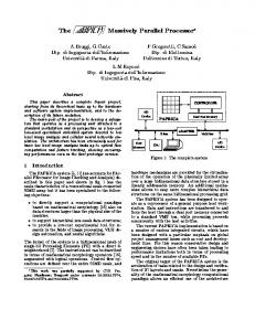
The schematic block diagram of a CBADP is given in Fig. 3 [12]. Each component of the diagram is described in the following sub-sections. A. Associative Memory An associative memory, also known as content-addressable memory (CAM), is defined as a collection of storage elements, called associative cells, which are accessed in parallel on the basis of data contents rather than by specific address or location. Each associative cell has the hardware capability to store and search its contents, in parallel, against the input data, and then indicate a match or mismatch by the state of a flipflop. CBADP associative memory consists of a comparand register which contains the data to be compared against the contents of the memory array, a mask register used to mask off portions of the data word(s) which do not participate in the operations, a memory array containing a collection of memory cells providing storage and search medium for the data, and a responder indicating success or failure of a search operation.
X
a
(one for each node N1, N2, N3) plus 1 Token Matching Time (at node N3) plus 1 Memory Fetch Time (at Node N3). In associative dataflow machine, the Fig. 1 dataflow graph would need only Total Search Time + Total Execution Time. It has been shown in [11] that associative dataflow processor, based on ADC, has much better peak and benchmark performance figures compared to typical dataflow machines.
d
Fig. 2. Dataflow graph to compute X=a+b+c+d inverted to allow progress of search phase
In traditional dataflow machine, execution of dataflow graph given in Fig. 1 would require 3 ALU Execution Times
There are two types of nodes in a dataflow graph, namely the action-node responsible for executing arithmetic or logic operation on the operands, and the control-node responsible for transferring the task of operation execution to some specific node when a certain condition is satisfied, as in case of branch operations. Depending upon the type of node, an associative memory word for action-node is of 80-bits length while a control-node word is of 18-bit length. Details about the format of the memory word can be found in [11]. Total number of words in the memory array are fixed at 64 to allow for up to 16 levels of dataflow graph with no more than four nodes per level. B. Complex Binary Processing Unit This unit is composed of four arithmetic and logic units to allow for up to four parallel operations corresponding to each node in a given level of the dataflow graph. Note that each CBALU is capable of handling arithmetic and logic operations in CBNS format, according to the algorithms described in Section II. Detailed designs of arithmetic circuits can be found in [13,14,15,16,17]. Currently, the instruction set of CBADP is composed of 21 instructions but there is a possibility of it to be extended to a total of up to 64 different instructions.
13 | P a g e www.ijacsa.thesai.org
(IJACSA) International Journal of Advanced Computer Science and Applications, Special Issue on Extended Papers from Science and Information Conference 2014 Complex Binary Associative Dataflow Processor
Control Unit
CU_SP
Counter CU_EP
Counter-value Register
Level Register
Complex Binary Processing Unit Associative Memory
CBALU0
CBALU1
CBALU2
CBALU3
Level Incrementer/ Decrementer Unit
Flags Registers FR0
FR1
FR2
FR3
Output Registers ZR0
ZR1
ZR2
ZR3
Input/Output System
Fig. 3. Schematic block diagram of Complex Binary Associative Dataflow Processor (CBADP)
C. Level Incrementer/Decrementer Unit To allow for 16 levels within a dataflow graph, a 4-bit level incrementer/decrementer unit is used to facilitate incrementing of the level number of the dataflow graph by one during the search phase and decrementing of the level number by one during the execution phase. Levels are labelled from top-tobottom of the dataflow graph in descending order. Since, during the search phase, the graph is assumed to be upsidedown, parent nodes are at the lower level and they are searching for children nodes which are at the higher level. This requires incrementing of the level number in the associative memory word as the search progresses. During the execution phase, the data is passed from nodes at higher level to the nodes at the lower level which requires decrementing of the level numbers as the execution phase continues. Given input E such that level incrementer/decrementer unit increments when E=0 and decrements when E=1, and current level number given by XOX1X2X3, the new level number L0L1L2L3 is given by the following Boolean equations: . : Logic AND +: Logic OR Xi^: Logic NOT @: Logic XOR L0 = E.[X0^.X1^.X2^.X3^ + X0.X2] + E^.[X0^.X1.X2.X3 + X0.X1^]
+ X0.[X1.X2^ + X1^.X3 + X2.X3^]
(1)
L1 = E.[X1.X2 + X1^.X2^.X3^] + E^.[X1.X2^ + X1^.X2.X3] + X1.[X2 @ X3]
(2)
L2 = E @ X2 @ X3
(3)
L3 = X3^
(4)
D. Control Unit Independent hardwired control units for search phase (CU_SP) and execution phase (CU_EP) have been designed for CBADP. A Hardware Programming Language (AHPL) has been used to write a total of 24 control sequences for CU_SP and 23 control sequences for CU_EP. Details of control unit design are presented in [11]. E. Counter This is a 6-bit up-down counter to keep track of up to 64 nodes which may be present in a dataflow graph to be executed on CBADP. Given input x1=0 such that the counter counts up by one from its current state x2x3x4x5x6x7 to the next state y0y1y2y3y4y5, and counts down when x1=1, the Boolean equations for the next state are given as follows:
14 | P a g e www.ijacsa.thesai.org
(IJACSA) International Journal of Advanced Computer Science and Applications, Special Issue on Extended Papers from Science and Information Conference 2014
produced by each CBALU. These registers are accessed by the Input/Output System which forms the interface to the outside world.
. : Logic AND +: Logic OR Xi^: Logic NOT @: Logic XOR
V.
y0 = x1.{x2.[x3 + x5 + x3^.x4^.x7^.(x5^ + x6)] + x2^.x3^.x4^.x5^.x6^.x7^} + x1^.{x2.[x3^ + x4^ + x3.(x4.x6.x7^ + x5.x6^)] + x2^.x3.x4.x5.x6.x7} + x2.(x4 @ x5)
(5)
+ x3^.x4^.x5^.x6^.x7^} + x1^.{x3.[x4^ + x5.x6^ + x4.x6.x7^] + x2.x4.x5.x6.x7} (6)
y2 = x1.(x4.x6 + x4^.x5^.x6^.x7^) + x1^.(x4.x5^ + x4^.x5.x6.x7) + x4.(x5.x6^ + x5^.x7 + x6.x7^)
(7)
y3 = x1.(x5 @ x6^.x7^) + x1^.{x5.x6^ + x6.[x5 @ x7]}
There is a natural communication gap between man and machine. Computer hardware operates at a very atomic level in terms of bits and bytes, whereas people tend to express themselves in terms of natural languages such as English or in mathematical notation. This communication gap is bridged by means of an artificial language which allows the man to express himself with a well-defined set of words, sentences, and formulas that can be "understood" by a computer. To achieve this interaction, the human is supplied with a user's manual which explains the constructs and meanings allowed by the language, and the computer is supplied with the software by which it can take a stream of bits representing the commands or programs written in the language by the human and translate this input into the internal bit patterns required to carry out the human's intent.
y1 = x1.{x3.[x4 + x4^.(x5^.x7 + x6.x7^)]
+ x3.(x4 @ x5)
CBADP SOFTWARE DESIGN ISSUES
(8)
y4 = x1 @ x6 @ x7
(9)
y5 = x7^
(10)
F. Counter-value Register This register (6-bit) is used to store the counter value at the completion of each successful search phase. This information is then used by the operating system in formulating an efficient execution phase for the given dataflow graph. G. Level Register This 4-bit register holds information about the maximum level number in the given dataflow graph. The control unit uses this information to ensure that all levels of the graph have been searched and executed. H. Flags Registers There are four of these registers corresponding to each CBALU in the complex binary processing unit. Each register holds carry, zero, negative, and overflow flags. I. Output Registers There are four of these registers corresponding to the output
A. Compiler A compiler takes as input a source program and produces as output an equivalent sequence of machine instructions. This process is so complex that it is not reasonable, either from a logical point of view or from an implementation point of view, to consider the compilation process as occurring in one single step. Not long ago, compilers were considered almost impossible programs to write. The design of a compiler for CBADP is required to follow the same phases as the ones used today for the design of any other type of compiler, namely lexical analysis, syntax analysis, intermediate code generation, code optimization, and then code generation. The programmer will be able to write programs in one of the high-level languages, such as C, Pascal, or Fortran, and then using the CBADP compiler, the source code will be converted to the machine instructions (in terms of 0 and 1), which will be fed to the hardware components within the complex binary associative dataflow processor for onward processing and execution. B. Operating System An operating system is a program that acts as an intermediary between the user of a computer and the computer hardware, and its purpose is to provide an environment in which the user can execute programs [18]. An abstract view of a CBADP system is given in Fig. 4. The CBADP provides the basic computing resources (associative memory, processing unit, registers) which are managed by the CBADP operating system, according to the user programs, which are written in some high-level language (such as C, Fortran, or Pascal) and have been converted into machine language using the CBADP compiler.
15 | P a g e www.ijacsa.thesai.org
(IJACSA) International Journal of Advanced Computer Science and Applications, Special Issue on Extended Papers from Science and Information Conference 2014
processing unit of the CBADP so that the instructions are executed in proper order.
User
For best CBADP performance, the ideal operating system should have multitasking capabilities so that more than one dataflow graph can be processed at a given time if the necessary resources, such as CBALUs and registers, are available. For example, to achieve maximum utilization of the complex binary processing unit, all four of the CBALUs must be kept busy all the time. If there are less than four nodes at any given level for execution, the multitasking operating system can assign the idle ALU(s) to another dataflow program which can run in parallel with the current dataflow program. In case of more than one dataflow program being processed on the ADP, the protection becomes an important issue to be addressed. That is, steps need to be taken to ensure that the proper execution of one graph does not interfere with the proper execution of the other dataflow graph(s) in the system.
CBADP compiler CBADP operating system Complex Binary Associative Dataflow Processor (CBADP)
VI.
Fig. 4. Abstract view of CBADP system
The CBADP operating system has several important functions for smooth and efficient processing of the user programs, and these are: Based on the information provided by the CBADP compiler about the given dataflow graph, design an efficient search phase for the program. Provide the system call to the CU_SP (control unit for search phase) for initiating the search phase of the dataflow graph. Acknowledge and handle any interrupts generated during the search phase to keep track of the information about the nodes (of dataflow graph) and their specific locations within the associative memory where they have been stored. Based on the information gathered during the search phase, design an efficient execution phase for the given dataflow graph. Provide the system call to the CU_EP (control unit for execution phase) for initiating the execution phase of the dataflow graph. Acknowledge and handle any interrupts generated during the execution phase to keep track of the information about the nodes (of dataflow graph) and their execution status in the system. In case of branch operations, enable or inhibit the appropriate controlnode depending upon whether the branch condition has been satisfied or not. Provide synchronization mechanism between the four arithmetic and logic units contained within the
CONCLUSIONS AND FURTHER RESEARCH
The design of a content-addressable memory-based associative dataflow processor, for which an Australian Innovation Patent has been granted, has been presented in this paper. Work on establishing complex binary number system as a natural enhancement of traditional binary number system is still in progress and the given complex binary associative dataflow processor design is still undergoing improvements and implementation optimization for field-programmable gate arrays (FPGAs). An avenue of further research in this area would be to incorporate CBNS in an image processor design or a digital signal processor design, two of the well-known areas where complex numbers are widely used, and then compare their performances with the processors implementing base 2 binary number system. Incorporating cache memories within the CBADP and then determining statistical performance analysis of such a system will be a valuable contribution to this area of engineering. These days, efforts are underway to design computer systems which mimic human brain. Since human brain behaves very much like associative memory, a contentaddressable parallel processor system, such as CBADP, may provide a useful tool for research in this area of interest to both medicine and engineering. The design of an operating system for CBADP is another interesting area of further research in this realm of computer engineering. ACKNOWLEDGMENT The concept of associative dataflow was developed at the Florida Institute of Technology (USA) during 1994-1996 when the author was pursuing doctoral studies there under the supervision of his research supervisor, Dr. R. G. Deshmukh. The author gratefully acknowledges the financial support provided by Sultan Qaboos University (Oman) for the CBNSrelated projects through various research grants over the past fourteen years. The research collaboration of Neville Holmes, David Blest, Bassel Arafeh, Amer Al-Habsi, Usman Ali, Amir Arshad Abdulghani, Ahmad Al-Maashari, and Said Al-Abri with the author on these projects is greatly appreciated. [1]
REFERENCES D. Knuth, “An imaginary number system,” Communications of the ACM, 1960, pp. 245-247.
16 | P a g e www.ijacsa.thesai.org
(IJACSA) International Journal of Advanced Computer Science and Applications, Special Issue on Extended Papers from Science and Information Conference 2014 W. Penney, “A numerical system with a negative base,” Mathematical Student Journal, May 1964, pp. 1-2. [3] W. Penney, “A binary system for complex numbers,” Journal of the ACM, April 1965, pp. 247-248. [4] V. Stepanenko, “Computer arithmetic of complex numbers,” Cybernetics and System Analysis, 1996, Vol. 32, No. 4, pp. 585-591. [5] T. Jamil, N. Holmes, and D. Blest, “Towards implementation of a binary number system for complex numbers,” Proceedings of the IEEE SoutheastCon 2000, Nashville, Tennessee (USA), April 7-9, 2000, pp. 268-274. [6] T. Jamil, “The complex binary number system – basic arithmetic made simple,” IEEE Potentials, December 2001/January 2002, Vol. 20, No. 5, pp. 39-41. [7] T. Jamil, Complex Binary Number System – Algorithms and Circuits, Springer, 2013. [8] D. Blest and T. Jamil, “Efficient division in the binary representation of complex numbers,” Proceedings of the IEEE SoutheastCon 2001, Clemson, South Carolina (USA), March 30-April 1, 2001, pp. 188-195. [9] D. Blest and T. Jamil, “Division in a binary representation for complex numbers,” International Journal of Mathematical Education in Science and Technology, 2003, Vol. 34, No. 4, pp. 561-574. [10] http://pericles.ipaustralia.gov.au/ols/auspat/applicationDetails.do?applic ationNo=2010100706 [11] T. Jamil, Introduction to Associative Dataflow Processing – From Concept to Implementation, VDM Verlag, 2010. [2]
[12] T. Jamil, “Design of a complex binary associative dataflow processor,” Proceedings of the 4th International Conference on Computer Engineering and Technology, Phuket, Thailand, May 27-28, 2012, pp. 32-35. [13] T. Jamil, B. Arafeh, and A. Al-Habsi, “Hardware implementation and performance evaluation of complex binary adder designs,” Proceedings of the 7th World Multiconference on Systemics, Cybernetics, and Informatics (SCI 2003), Orlando, Florida (USA), July 27-30, 2003, Vol. II, pp. 68-73. [14] J. Goode, T. Jamil, and D. Callahan, “A simple circuit for adding complex numbers,” WSEAS Transactions on Information Science and Applications, July 2004, Vol. 1, No. 1, pp. 61-66. [15] T. Jamil, A. Abdulghani, A. Al-Maashari, “Design of a nibble-size subtractor for (-1+j)-base complex binary numbers,” WSEAS Transactions on Circuits and Systems, July 2004, Vol. 3, No. 5, pp. 1067-1072. [16] T. Jamil, A. Al-Maashari, and A. Abdulghani, “Design and implementation of a nibble-size multiplier for (-1+j)-base complex binary numbers,” WSEAS Transactions on Circuits and Systems, November 2005, Vol. 4, No. 11, pp. 1539-1544. [17] T. Jamil and S. Al-Abri, “Design of a divider circuit for complex binary numbers,” Proceedings of the World Congress on Engineering and Computer Science 2010/International Conference on Circuits and Systems, San Franscico, California (USA), October 20-22, 2010, Vol. II, pp. 832-837. [18] A. Silberschatz and P.B. Galvin, Operating System Concepts, AddisonWesley Publishing Company, 1994.
17 | P a g e www.ijacsa.thesai.org