5th International Conference on Control Engineering&Information Technology (CEIT-2017) Proceeding of Engineering and Technology –PET Vol.34 pp.39-44
5th International Conference on Control Engineering & Information Technology (CEIT2017) , 17-19 December,2017, Sousse , Tunisia,
Design of a Flight Control System Based On HILS Test Platform 1
1
(Daw
M. Al-Zentani)
(Department, Electrical & Electronics Engineering, Zawia University, Alzawia, Libya)
[email protected] 2
2
(Amer Zerek) (Department, Electrical & Electronics Engineering, Zawia University, Alzawia, Libya)
[email protected] 3
3
(Ali
Mohamed Elmelhi)
(Department, Electrical & Electronics Engineering, Tripoli University, Tripoli, Libya)
[email protected]
Abstract: In this Paper the Hardware-In-the-Loop Simulation (HILS) platform is used to design a flight Control system for Unmanned Aerial Vehicles (UAV). A flight Controllers are designed and validated for lateral and longitudinal axes motion using Matlab/Simulink offline simulations and the designed controllers are embedded To the HILS platform for Real time simulation. It is observed that the resulting controller successfully stabilizes the aircraft to achieve flight Trajectory.
Keywords: UAV, autopilot, PID controller, Hardware-Inthe-Loop-Simulation, flight control, SISO, MIMO, Xpc target, Real time simulation, flight Trajectory.
1.
INTRODUCTION
The modern aerospace vehicles and flight control systems has recently great importance in both military and civil applications. The field of Unmanned Air Vehicles (UAVs) is aircraft characterized by the absence of a pilot on board and represent very promising vehicle for flight in outdoor environment. Their flight is managed by means of a proper control system, under the supervision of a navigator or pilot on the ground. the flight operations of an UAV must comply with the same rules and procedures of the aircraft with on board pilot and flight crew. In fact, in recent years, the guidelines of flight certification for UAVs are designed to provide an increased reliability, accuracy and safety. UAVs are widely used both in military and civil application such as fire prevention and emergency operations, surveillance, search and rescue. It is clear that the main goal of UAVs consists in avoiding any risk for pilots and aircrew and allowing the execution of “dull, dirty and dangerous” missions, often at a lower cost than conventional aircraft. For this reason, a relevant feature of UAVs is related to flight management and trajectory control strategy with the aim of automatically reaching a desired position under a specific orientation [1]. Autopilot systems are a major area of design for UAVs. These systems perform autonomous flights. A flight mission can be done without human input [2]. If an airplane is to remain in steady uniform flight, the resultant forces as well as the resultant moment about the center of gravity must both be equal to zero. An airplane satisfying this requirement is said to be in a state of equilibrium of flying at a trim condition [3]. In this paper we outline an approach based on a hardware-in-the-loop simulation platform for building a stabilizing controller for UAVs. A suitable flight condition is designed by MATLAB/Simulink Copyright IPCO-2017 ISSN 2356-5608
Environment simulation to design a controller for UAVs. Flight control surfaces are selected as the inputs of the system to hold the UAV in this condition by trimming and linearizing using MATLAB’s features. The step next is based on these trim points of the system, where nonlinear flight dynamical equations are linearized. There are several types of controller can be used for UAVs, Like LQR, Full State Feedback controller, PID Controller, but PID controller is preferred and designed due its simplicity. Both manual calibration and MATLAB’s automated design tools are used to determine the PID coefficients. 2. 1.
DESIGN PHASE
Controller Design
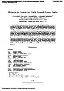
A general treatment of the stability and control of airplanes requires a study of the dynamics of flight [4]. Much useful information can be obtained, however, from a more limited view, in which we consider not the motion of the airplane, but only its equilibrium states. This is the approach in what is commonly known as static stability and control analysis [4]. Elevators and ailerons are flight control surfaces. Elevators are surfaces on the tail plane (the horizontal part of the tail assembly). While the entire tail plane surface helps stabilize the aircraft during flight, the elevators apply pitch by angling the trailing (rear) edge of the tail plane up or down. Ailerons are surfaces on the outer, trailing edge of each wing. They angle in opposite directions to waggle the wings up and down or roll the aircraft about its nose -tail axis. Fig. 1 shows the classic layout for a conventional and Delta Wing UAV. This rolls one wing up and forces the other wing down, effectively rolling the airplane [5].
Figure 1. Flight control surfaces on UAV.
5th International Conference on Control Engineering & Information Technology (CEIT2017) , 17-19 December,2017, Sousse , Tunisia,
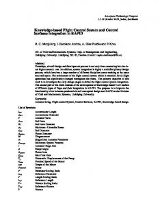
1) Elevator controller "θ" The number and types, of aerodynamic surfaces to be controlled, changes with aircraft category [5]. Aircraft have a number of different control surfaces: those indicated in Colored form the primary flight control, i.e. pitch, roll and yaw control, basically obtained by deflection of elevators, ailerons and rudder (and combinations of them)[6]. Elevator angle is given as an input to the Simulink model and theta angle is as an output. And with the same Mainer, The yaw and roll angles are given as an input commands, psi and phi as output. Firstly, Aerospace Blockset in MATLAB/ Simulink library is used for the aircraft dynamic model. Lightweight Aircraft model’s aerodynamic derivatives are followed up. By using this aircraft model a Simulink model is established. It can be seen in Fig. 2. Determining the cruise speed and altitude condition, trimming and linearization is obtained.
After linearization based on the operation point and system’s minimal implementation is calculated, first step was designing the PID controller by MATLAB's Design tools (sisotool). Closed loop step response provided by PID controller and the input which is applied are shown in Fig. 3. Also it can be seen the input is reasonable. PID control structure is built for supported flight mode applied to the Simulink model’s input which is the change of the elevator angle is shown in the Fig. 4. The output of the system theta angle is shown in the Fig. 5. Designed controller’s impact of the other angles can be seen in the Fig. 5. It can be seen that the psi and phi angles are not affected from the controller and remained around zero.0.
Figure 2. The Simulink Model for Flight control system.
After linearization based on the operation point and system’s minimal implementation is calculated, first step was designing the PID controller by MATLAB's Design tools (sisotool). Closed loop step response provided by PID controller and the input which is applied are shown in Fig. 3. Also it can be seen the input is reasonable. PID control structure is built for supported flight mode applied to the Simulink model’s input which is the change of the elevator angle is shown in the Fig. 4.
Figure 5. Changes of psi, theta and phi as results of the applied Controller
2) Aileron controller "Φ" Aileron is the control surface which operates the rolling of the UAV. This surface is the input of the MATLAB model. The output is the phi angle which is the rolling angle. After linearization based on the operation point and obtained systems minimal implementation and PID controller’s transfer function is calculated by MATLAB sisotool. Derivative filter is used to create a more resistant against noises and more realistic D parameter. Closed loop step response provided by PID controller and the input which is applied are shown in Fig. 6. Also it can be seen the input and output are reasonable.
Figure 3. Theta output and elevator input step responses
Figure 4. Changes of elevator, aileron, rudder and throttle For applied controller.
Figure 6. Phi output and aileron input step responses for the PID
5th International Conference on Control Engineering & Information Technology (CEIT2017) , 17-19 December,2017, Sousse , Tunisia,
PID control structure is built for supported flight mode applied to the Simulink model’s input which is the change of the aileron angle is shown in the Fig. 7. The output of the system phi angle is shown in the Fig. 8. Response settles without overshoot and around 3 seconds. Designed controller’s impact of the other angles can be seen in the Fig. 7 and Fig. 8. When the UAV roll over to its side the theta angle should change a bit because of the flight dynamics cross impacts. Besides UAV will turn in time which means psi angle will change. If these cross angles are undesirable, for instance if UAV’s rolling over without changing theta is desired, two controllers (elevator-theta and aileron- phi) should be used together or multiple input multiple output controller should be designed.
been promoted as the predominant tools for multivariable system analysis, the classical control extensions offer several advantages, including requiring only an inputoutput map and providing direct insight into stability, performance and robustness of MIMO systems [7]. It is needed to be checked as if the elevator -theta and aileron -phi single input single output system controllers are working together. For this reason, both SISO system controllers are implemented at the same time. It can be Seen in the Fig. 9 in the Simulink model, elevator and aileron are as inputs and theta and phi angles are as
Figure 9. The Simulink model for MIMO system
outputs. It turned out those results, where remain the same as the single input and single output systems. The corresponding figures could not be included here due to space limitations but they were exactly the same outcomes as in Fig. 4-Fig. 5 and Fig. 7-Fig. 8. It is needed to be checked as if the elevator -theta and aileron -phi single input single output system controllers are working together. For this reason, both SISO system controllers are implemented at the same time. It can be Figure 7. Changes of elevator, aileron, rudder and throttle as results of the applied controller.
Figure 8. Changes of psi, theta and phi as results of the applied controller.
3) Multivariable control system design Classical control tools have been popular for analysis and design of Single-Input, Single-Output (SISO) systems [7]. These methods may be viewed as specialized versions of more general tools that are applicable to Multi-Input, Multi-Output (MIMO) systems [7]. Although modern “state-space” control methods (Relying on dynamic models of internal structure) have
3. HILS TEST PLATFORM For the design, implementation and testing of control systems Hardware-In-the-Loop Simulation (HILS) simulation is increasingly being required, where some of the control-loop components are real hardware, and the others are software [8]. State space technique isn't always suitable for controlling UAVs. It’s needed to be sure that simulation results are good enough to take a flight test with the designed autopilot. To achieve this pre -flight tests which are done by flight simulation are used. Hardware -in -the -loop simulation technique is used in this project as flight simulation. HIL simulation is chosen because actual autopilot and its Inertial Measurement Unit (IMU) can be integrated with simulation. HIL simulation technique needs simulation software and a Hardware platform that use to integrate real values to simulation (Fig.10.b). For simulation software Xpc target and Real time windows target From Math-works are chosen because this program let user review and transfer data to any other UDP enabled application and it has various types of plane models. Also the autopilot is designed for Lightweight Aircraft model is included in this software. And a platform which performs two axis movements (roll, pitch) to integrate autopilot’s IMU is used. Micropilot 2028 is used as autopilot. Because Micropilot has its own microcontroller, 6 DOF IMU and barometer, it is chosen. Also it is easy to program Micropilot. The communication application is used to run all of these in order.
5th International Conference on Control Engineering & Information Technology (CEIT2017) , 17-19 December,2017, Sousse , Tunisia,
Stabilizer is the first step of designing autopilot to test it at stabilizing mode. Reliable autopilot matrixes have Been chosen, after tests are made. Selected autopilot’s results are shown in Fig. 12.
Figure (10. a) Micropilot 2028
Figure 12. Roll axes stabilization results
Figure (10. b) HIL test platform using Xpc target
HIL simulation performs as follows. Plane fly as Real time Simulink Model on the target computer (6-DOF) generates roll yaw and pitch angle values. These angles values sending to the platform’s microcontroller. unit over serial port communication protocol. Platform’s microcontroller reads these values as reference values for pitch roll and yaw axis PID coefficient. Platform output and PID inputs are obtained by reading encoders which are connected to motors’ shafts. Then each PID controller calculates their output and drives related motors which are individually connected to separate control surfaces. That surface is placed to desired angle. Therefore autopilot can be put over this platform and can operate on its own. Also transmitter and receiver are needed to give command to autopilot. Autopilot calculates new values for aileron and elevator according to given command and send them to serial port. The communication applications read them and send them to target PC. Running UAV real time model and displaying the flight control parameters on Host computer using Xpc target Fig.10.b. And UAV state is changed based on these changes, new angle values are occurred. Selected autopilot’s results are shown in Fig. 11
In Fig. 11 and Fig. 12 the autopilot created runs in stabilizer mode. In this mode it is possible to do maneuvers like rolls and loops but if the sticks were released then autopilot will level the plane. It can be seen that the plane is levelled when maneuvers were done in the Fig. 12. Maneuvers were done for pitch angle at 12th to 14th seconds of simulations and levelled at around 17th seconds. Maneuver was done for roll angle around 16th second of simulation and levelled around 17th second then another maneuver was done around 19th second of simulation and levelled around 2 seconds of simulations. Other times stabilizer mode of autopilot was not been active. The autopilot and IMU unit are fixed to The HILS test plate form, we use the 3-axis table that available in the Engineering research center In Tripoli Libya. 3. CONCLUSION AND FUTURE WORK In this paper we outlined the design of elevator and aileron stabilizer for UAVs and using data obtained from Xpc target real time simulation. These data are processed by a system identification process utilizing MATLAB and a dynamically model of the aileron and elevator behaviors are obtained. These models are used to construct PID controllers for these surfaces and hardware in the loop simulations using a custom 3 degree of freedom moving platform (3-dof). Confirm that the designed controllers successfully. In future work surface loss scenarios are considered and to eliminate the impact of these losses controllers will be developed based on this study. The assumptions of channel Coupling and dis Coupling of autopilot should take in account.
ACKNOWLEDGEMENTS The authors would like to thank the Scientific and Technological Research Center of Tripoli (Libya) for supporting this work under project agreements. Figure 11. Pitch axes stabilization results
5th International Conference on Control Engineering & Information Technology (CEIT2017) , 17-19 December,2017, Sousse , Tunisia,
REFERENCES [1]
J. Gundlach, Designing Unmanned Aircraft Systems: A Comprehensive Approach, Virginia: AIAA Education Series, 2012.
[2]
H. Korkmaz, O. B. Ertin, C. Kasnakoglu, and Ü. Kaynak, “Design of a flight stabilizer system for a small fixed wing unmanned aerial vehicle using system identification,” Advances in Control and Automation Theory for Transportation Applications, September 16-17, 2013.
[3] R. C. Nelson, Flight Stability and Automatic Control, Second Ed., McGRAW-HILL International Editions: Aerospace Science & Technology Series, 1998. [4] B. Etkin and L. D. Reid, Dynamics of Flight Stability and Control Third ed., Hamilton Printing Company, 1995. [5] The Basics of Flight. [Online]. Available: http://www.aviastar.org/theory/basics_of_flight/control.html [6] Aircraft Systems–Lecture Notes–Chapter 6-Flight Control System, Polytechnic of Milan. [Online]. Available: www.aero.polimit.it/~l050263/bacheca/Dispense_EN/06wFligCont.pdf [7] M. L. Nagurka and T. R. Kurfess, New Design Paradigms for MIMO Control System Synthesis, Carnegie Mellon University Engineering Design Research Center, 1991. [8] R. Isermann, J. Schaffnit, and S. Sinsel, “Hardware-in-the-loop simulation for the design and testing of engineering control systems,” Control Engineering Practice, vol. 7, no. 5, pp. 643-653, May 1999.
Daw M. Al-Zentani obtained B.S. from ALfatah University Libya in 1992 and M.S. degrees from Belgrade University, Serbia, in 1997 and Ph.D. degrees from Belarusian state University, in 2006 and He is currently participate professor in the Department of Electrical and electronic Engineering at AZAWIA University of Electrical and electronic Engineering in AZAWIA , Libya. Dr. Daw M. Al-Zentani’s current research interests include control system and mecatronic and embedded systems.