Abstract: - This research paper describes the design of a room temperature and
humidity controller using fuzzy logic. The proposed model consists of two fuzzy ...
American Journal of Engineering Research (AJER)
2013
American Journal of Engineering Research (AJER) e-ISSN : 2320-0847 p-ISSN : 2320-0936 Volume-02, Issue-11, pp-86-97 www.ajer.org Research Paper
Open Access
Design of A Room Temperature And Humidity Controller Using Fuzzy Logic Tarun Kumar Das, Yudhajit Das 1
Asst. Professor, Department Of Electronics And Comm. Engineering, Future Institute Of Engg & Management, West Bengal University Of Technology, India 2 Department Of Electronics And Comm Engineering, Future Institute Of Engineering & Management, India
Abstract: - This research paper describes the design of a room temperature and humidity controller using fuzzy logic. The proposed model consists of two fuzzy logic controllers to control temperature and humidity respectively. The first controller accepts two input values- the current temperature as detected by temperature sensor and its deviation from user set-temperature, and controls the speed of heat-fan and cool-fan accordingly . When the current temperature in the room reaches set point, it serves as one of the input for second fuzzy logic controller that controls the humidity. The ideal relative humidity level for user’s set temperature is preset in the system. Current humidity in % as detected by the humidity sensor in the room serves as the second input to the controller. The humidifier and exhaust fan speed is controlled accordingly to maintain the correct humidity level for that temperature. This research work will increase the capability of fuzzy logic control systems in process automation with potential benefits. MATLAB-simulation is used to achieve the designed goal.
Keywords: - Fuzzy logic, Inference Engine, Matlab Simulation, Rule Selection I.
INTRODUCTION
A control system is a device, or set of devices, that manages, commands, directs or regulates the behavior of other device(s) or system(s). Industrial control systems are used in industrial production for controlling an equipment or a machine. The control system design, development and implementation need the specification of plants, machines or processes to be controlled. A control system consists of controller and plant, and requires an actuator to interface the plant and controller. The behaviour and performance of a control system depend on the interaction of all the elements. [2] Computational Intelligence (CI) is a field of intelligent information processing related with different branches of computer sciences and engineering. The fuzzy systems are one paradigm of CI. The contemporary technologies in the area of control and autonomous processing are benefited using fuzzy sets. One of the benefits of fuzzy control is that it can be easily implemented on a standard computer. In contrast with traditional logic theory, where bi- nary sets have two-valued logic: true or false, fuzzy logic variables may have a truth value that ranges in degree between 0 and 1. Fuzzy logic has been extended to handle the concept of partial truth, where the truth value may range between completely true and completely false. Fuzzy logic imitates the logic of human thought, which is much less rigid than the calculations computer generally perform. Intelligent control strategies mostly involve a large number of inputs. The objective of using fuzzy logic has been to make the computer think like people. Fuzzy logic can deal with the vagueness intrinsic to human thinking and natural language and recognize its nature is different from randomness. Using fuzzy logic algorithm, we could enable machines to understand and respond to vague human concept such as hot, cold, large, small, etc. [1] [2] This proposed design work of room temperature and humidity controller can be used in a processing plant to maintain comfortable atmosphere in the environment.
www.ajer.org
Page 86
American Journal of Engineering Research (AJER) II.
2013
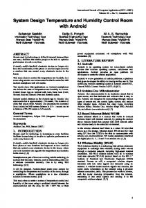
BLOCK DIAGRAM OF PROPOSED MODEL:-
Figure 1: Block Diagram Of Room Temperature And Humidity Controller The basic model of the proposed structure consists of room temperature and humidity controller with fuzzy logic control system. The room atmosphere controller has a heating fan, a cooling fan to heat or cool the room according to user demand ; a humidifier to release moisture in the air and a exhaust fan to dry out the air if the relative humidity is higher than the needed range. Humidity and temperature sensors used to monitor the environment of room are mounted in the room and are connected with the fuzzifiers of the two fuzzy logic control system. 2.1.Simplified Diagram For The Prposed System:-
III.
HOW HEATING AND COOLING IS DONE
The model basically employs the principle of ground water/air source reversible heat pumps which work in either thermal direction to provide heating or cooling to the internal space. In cooling mode, the inside coil is the evaporator and the outside coil is condensor. The compressor takes away the low pressure vapour from the refrigerant and discharge it as high pressure vapour which thereby enters the condensor where it is cooled and condensed into liquid. After leaving the condensor as high pressure cooler liquid, the refrigerant now enters the evaporator where it changes into vapour coming in contact with low pressure atmosphere. During this evaporative cycle, heat is removed from the air which gets cooler and enters the room. The low pressure refrigerant then routes back to the compressor by suction line to repeat the cooling process. In heating mode, the inside coil is now condensor and outside coil is evaporator. The compressor sends the high pressure vapour into the reversing valve which routes the vapour to the condenser coil where it is cooled, and condensed into liquid by passing through the coil. The heat removed from the refrigerant is expelled to the inside air by the air movement system. The refrigerant leaves the inside coil as a high pressure liquid. When this liquid enters the low pressure atmosphere of the outside coil (evaporator) it evaporates into vapor. When the evaporative process takes place, heat is removed from the air flowing through the evaporator and the air,which is now cool, is returned to the outside air (ambient). From the evaporator, the low pressure refrigerant vapour returns to the reversing valve which routes the low pressurevapour to the compressor through the suction line to start the heatingprocess again. [2]
www.ajer.org
Page 87
American Journal of Engineering Research (AJER)
2013
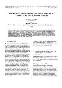
A heat pump with one extra valve allows the condenser (hotcoil) and evaporator (cold coil) to reverse places in the winter. Figure 2 shows close-ups of this “reversing” valve and where it is located in the heat pump system.
Figure 2:- Reversing Valve That Enables Both Heating And Cooling Processes
IV.
DESIGN ALGORITHM OF FUZZY LOGIC FOR ROOM TEMPERATURE & HUMIDITY CONTROLLER
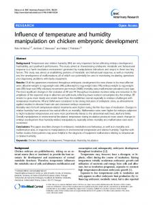
This simplified design algorithm is used to design the fuzzifier, inference engine, rule base and defuzzifier for the room air conditining system according to the control strategy of the processing plant to achieve the quantity and quality of the desire needs to maintain the room environment. The model can operate within 8’C to 44’C temperature range. And user can set any desired temperature from 18 to 26. For any temperature within 18 to 26 both temperature and humidity controlling part of the proposed model performs well to maintain the comfort atmosphere of the user. The humidity comfort level is pre defined and works perfectly within temperature range 18 to 26(oC). 4.1.Fuzzifier:4.1.1.Membership Functions And Ranges For The First Fuzzy Logic Controller For Controlling The Desired Temperature 4.1.1.1.Input Variables:4.1.1.1.1.Current Temperature:It is the current temperature of the room as recorded by the temperature sensor mounted in the room. The sensor range should be wide enough to take care of climatic and regional fluctuations. The proposed model works perfectly at any temperature within range 8oC-44oC Table 1: Membership Functions For Current-Temperature MEMBERSHIP FUNCTIONS RANGE (oC) COLD COOL NORMAL WARM HOT VERY-HOT EXTR-HOT
8-14 13-19 18-22 21-27 26-32 31-39 38-44
4.1.1.1.2.Deviation From Set Temperature It gives the difference between the user preferred temperature and current temperature of the room as recorded by the temperature sensor in the room. As this model can work between temperature range 8-44’C and user can set any desired temperature from 18-26’C, so temperature difference between the current and the user preferred temperature can never go beyond -26’C (18’C – 44’C) and 18’C (26’C - 8’C). Thus (-26’C) & (+18’C) are the lower and upper limits of the input variable “ deviation from set-temperature”). Table 2: Membership Functions for “Deviation from current temperature” MEMBERSHIP FUNCTIONS RANGE(oC) NE2 NE1 NL NS O PS PL
www.ajer.org
-26 to -19.5 to -13 to -7 to -2 to 1 to 9 to
-18.5 -12 -6 0 2 10.5 18
Page 88
American Journal of Engineering Research (AJER)
2013
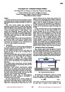
Figure 3:-Plot Of Membership Functions For “ Current-Temperature” & “Deviation from current temperature” 4.1.1.2.Output Variables 4.1.1.2.1.Heat-Fan-Speed The heat fan can either be in ON or OFF state depending on the temperature preference in the room. The hetafan-speed is catagorised into 1. STOP 2.HEAT-SLOW 3. HEAT-MEDIUM 4. HEAT-FAST. If the current temperature of the room is below the desired temperature then this fan automatically gets on varies speed according to temperature difference. Table 3:-Membership Functions For “heat-fan-speed” MEMBERSHIP RANGE FUNCTIONS % STOP 0-5 HEAT-SLOW 0-45 HEAT-MEDIUM 35-65 HEAT-FAST 60-100 4.1.1.2.2.Cool-Fan-Speed The cool-fan-speed is catagorised into 1. STOP 2.COOL-SLOW 3. COOL-MEDIUM 4. COOL-FAST. If the current temperature of the room is above the desired temperature then this fan automatically gets on varies speed according to temperature difference. Table 4:-Membership Function For “cool-fan-speed” MEMBERSHIP FUNCTIONS RANGE % STOP 0-5 COOL-SLOW 0-30 COOL-MEDIUM 25-50 COOL-FAST 45-80 COOL-V.FAST 75-100
Figure.4:-. Plot Of Membership Function For “heat-fan-speed & cool-fan-speed” 4.1.2.Membership Functions And Ranges For The Second Fuzzy Logic Controller For Controlling The Relative Humidity
www.ajer.org
Page 89
American Journal of Engineering Research (AJER)
2013
4.1.2.1.Input Variables 4.1.2.1.1. Current Temperature This input variable of the second fuzzy logic controller is dependant entirely on the temperature sensor. As the user is allowed to choose the desired temperature between 18-26’C, so this temperature range is divided into two membership functions. Table 5:- Membership Function For “current-temperature” MEMBERSHIP RANGES(oC) FUNCTIONS Temp-range-A 16-22.5 Temp-range-B
22-28
4.1.2.1.2.Current-Humidity Relative Humidity is the percentage of water vapour the air is holding, in relation to the amount it is capable of holding at a given temperature.The Proper Indoor Humidity [3] that gives comfortable atmosphere depends on temperatures, as indicated here: Table 6:- Proper Indoor Humidity If Outdoor Temperature Is:
Relative Humidity That Should Be Maintained
86’F (30’C ) 80.5’F (27’C) 77’F (25’C) 71.5’F (22’C) 68’F (20’C) 62.5’F (17’C) 59’F (15’C )
56% 54% 50.5% 45% 43.5% 40% 35%
The most recent advancement in humidification is a humidifier that automatically delivers the optimum RH without periodic homeowner adjustment.The humidification part is designed in this model in such a way that the user does not have to set any particular humidity. The comfort feeling humidity level within user settable temperature range (18-26C ) is pre-set here . from 18(oC) to 22(oC) the ideal comfort RH level is taken as 45%. And from 23-26’C the ideal RH level is taken as 50-54%. Table 7:-Membership Functions for Current-Humidity MEMBERSHIP FUNCTIONS RANGE (%) DRY 0-21 NOT TOO DRY (NTD) 20-43 SUITABLE-1 (S-1) 42-48 SUITABLE-2 (S-2) 46-54 NOT TOO WET (NTW) 53-75 WET 70-100
Figure 5:-Plot Of Membership Functions for “Current Temperature” & “Current Humidity”
www.ajer.org
Page 90
American Journal of Engineering Research (AJER)
2013
4.1.2.2.Output Variables 4.1.2.2.1.Humidifier Table 8:-Membership Functions for Humidifier MEMBERSHIP FUNCTIONS RANGE (%) DRY 0-5 SLOW 4.5-35 MEDIUM 28-62 FAST 60-100 4.1.2.2.2.Exhaust-Fan Table 9:-Membership Functions for Exhaust-Fan MEMBERSHIP FUNCTIONS RANGE(%) STOP 0-5 SLOW 4.5-35 MEDIUM 28-62 FAST 60-100
Figure 6:- Plot of Membership Functions For “Humidifier” & “Exhaust-fan-speed” 4.2.Rule Base :Table 10 :- Rule Base For First Fuzzy Logic Controller RULE NO 1. 2. 3. 4. 5. 6. 7. 8. 9. 10. 11. 12. 13. 14. 15. 16. 17. 18. 19. 20. 21. 22.
CURRENT-TEMP Cold Cold Cool Cool Cool Cool Normal Normal Normal Warm Warm Warm Warm Hot Hot Hot Very-Hot Very-Hot Very-Hot Very-Hot Extrm-Hot Extrm-Hot
www.ajer.org
DEVIATION FROM SETTEMP PL PS PL PS O NS PS O NS PS O NS NL NS NL NE1 NS NL NE1 NE2 NE1 NE2
HEAT-FANSPEED Heat-Fast Heat-Medium Heat-Medium Heat-Slow Stop Stop Heat-Slow Stop Stop Heat-Slow Stop Stop Stop Stop Stop Stop Stop Stop Stop Stop Stop Stop
COOL-FANSPEED Stop Stop Stop Stop Stop Cool-Slow Stop Stop Cool-Slow Stop Stop Cool-Slow Cool-Medium Cool-Slow Cool-Medium Cool-Fast Cool-Slow Cool-Medium Cool-Fast Cool-V.Fast Cool-Fast Cool-V.Fast
Page 91
American Journal of Engineering Research (AJER)
2013
Table 11 :- Rule Base For Second Fuzzy Logic Controller RULE NO. 1 2 3 4 5 6 7 8 9 10 11 12
CURRENT TEMPERATURE Temp-Range-A Temp-Range-A Temp-Range-A Temp-Range-A Temp-Range-A Temp-Range-A Temp-Range-B Temp-Range-B Temp-Range-B Temp-Range-B Temp-Range-B Temp-Range-B
HUMIDITY DRY NTD S-1 S-2 NTW WET DRY NTD S-1 S-2 NTW WET
HUMIDIFIER SPEED Fast Medium Stop Stop Stop Stop Fast Medium Slow Stop Stop Stop
EXHAUST FAN SPEED Stop Stop Stop Slow Medium Fast Stop Stop Stop Stop Medium Fast
Figure 7:-Matlab Rule Editor for temperature & humidity controller 4.3.Fuzzification:We select two random values of input variables from first fuzzy logic controller to demonstrate how fuzzification is done in both the fuzzy logic controller used in this system. In the first fuzzy logic controller, the signal value of current-Temperature=13C intersects with fuzzy variables "Cold" and "cool", where "cold" is taken as the first fuzzy variable f[0] and "Cool" is the second fuzzy variable, f[1]. The f[0] maps to the membership function value of 0.86 while f[l] maps to the value of 0.13. Similarly, for the input value of “deviation-from current-temperature”=+10,the corresponding intersection of fuzzy variables are "PS" as the second active fuzzy variable f[2] and "PL" as the first active fuzzy variable f[3]. The f[2] will thereby map to the membership function value of 0.04 while f[3] corresponds to 0.96. Table 12 :- Results Of Fuzzification:INPUT VARIABLES CURRENT TEMPERATURE DEVIATION-FROMSETTEMPERATURE
VALUES 13
REGION SELECTION 0