Design of FPGA-Controlled Power Electronics and Drives Using MATLAB Simulink Graham E. Town
Yam P. Siwakoti
Department of Engineering Macquarie University, NSW-2109, Australia.
[email protected]
Abstract-We
present
a
simple
and
Department of Engineering Macquarie University, NSW-2109, Australia.
[email protected]
rapid
prototyping
HDLCoding
technique for Field Programmable Gate Array (FPGAs)-based
,
digital controllers for power electronics and motor drives using MATLAB's Simulink and HDL Coder design software. The MATLAB/Simulink models
are
optimized
target independent, specific and traceable
and
Manual Coding
converted to
Very High Speed
Integrated Circuit Hardware Description Language
HDL CoderlMatiab Coder
(VHDL)
code for FPGA programming. An example implementation of the
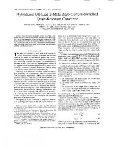
Fig. 1. HDL Coding methods for FPGA Programming
space vector pulse width modulation (SVPWM) technique is presented, illustrating the design of a generic 3-phase voltage
Simulink and optimizes the models to meet speed-area-power objectives for the FPGA. The MATLAB environment provides two model-based tools for rapid system development: i) Xilinx System Generator and ii) HDL Coder. Either of these approaches provide an effective FPGA design flow when used independently. However, (as pointed out in [3]) "some projects benefit from a mixture of approaches - a workflow that combines the native Simulink workflow, device-independent or device-specific code, and code readability offered by Simulink HDL coder, with the Xilinx FPGA-specific features and optimizations offered by Xilinx System Generator." [3] Model-based design in MATLAB & Simulink environment for FPGA prototyping is very flexible and makes implementation of control algorithms in FPGA for power electronics and motor drives a lot faster with no need of special attention to internal connections in the device prototype. The prototype is used to verify various modulation strategies, control functions, and power flow regulation algorithms for various tailor made power electronic design and motor control applications in minimum time. Thus, by using an FPGA-based
source inverter (VSI). Simulation and co-simulation, system level design, and verification for rapid prototyping of FPGA-based digital controllers will assist power electronics engineers and researchers to develop and prototypes in a relatively short time by eliminating tedious and time-consuming manual coding. This enables increased productivity and facilitates the development of power
electronic
controllers
with
more
complex
control
algorithms. Index Terms-FPGA, rapid prototyping, model based design, digital control, power electronics and drives, SVPWM.
I. INTRODliCTION
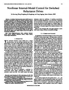
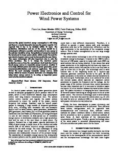
The design of modern power electronic circuits and systems requires knowledge from multiple discipline areas, including digital control, to develop innovative and custom designed products and solutions in a short period of time [I]. MATLAB & Simulink enable an alternative way to automatically generate readable and portable IEEE standards compliant HDL (i.e. IEEE 1076 compliant VHDL code and IEEE 1364-2001 compliant Verilog code) from MATLAB, Simulink and Stateflow models for a variety of FPGAs. Fig. 1 shows the various ways to generate HDL from MATLAB & Simulink. Manual coding is tedious, time consuming and error prone. On the other hand, automatic code generation lets designers to make changes in the system level model, and produce an updated HDL implementation in minutes by regenerating the HDL code. Fig. 2 (from [2]) illustrates the comparison of model-based design using HDL coder and manual coding. Model-based design reduces the total project development time by 33% as compared to manual coding. In addition, MATLAB model-based design facilitates creation of FPGA-based prototypes and automates HDL code verification by co simulating it with
978-1-4799-0482-2/l3/$31.00 ©20l3 IEEE
I
o
� � II
20
Requirements Phase HDL Creation
40
60 Schedule time (%)
iii
Functional Design HDL Verification
80
� D
100
Detailed Design Hardware Iteration
Final ASIC/FPGA Implementations
Fig. 2. Comparison of time spent on FPGA prototyping by MATLAB Simulink model-based design and direct manual HDL coding [2].
571
controller, the designer is able to build a fully dedicated digital system that is perfectly adapted to the control algorithm being implemented. Moreover, FPGA technology is now considered very useful by an increasing number of designers in myriad fields of application due to short implementation time, confidentiality of the algorithm and architecture, capable to meet many constraints for space applications, and it can be adapted to any change in design by dynamic reconfiguration [4]. Some of the benefits of using FPGA for controlling of electrical systems compared to counterpart DSPs and microcontrollers are made clear in the same paper. Tn fact, FPGA-based digital controllers have been implemented with success in many different applications, such as power converters (e.g. PWM control of DC-DC converters) [5-6], point of load converter [7], pulse width-modulated (PWM) inverters [8-9], resonant inverters [10], power-factor correction [II], interleaved converters [12], multilevel converters [13], multilevel and matrix converters [14], fuzzy logic control of power converters and electrical drives (e.g. induction machine drives) [15-16], synchronous machine drives [17], neural network control of induction motors [16], and switched reluctance motor drives [18]. However, FPGA prototyping and design remains a mystery to many novice power electronics designers who do not have a basic knowledge of VHDL or Verilog coding. In the same context, even manual coding experts find it difficult to meet the short implementation times, due to the time required for debugging, modification of the control algorithms, and reimplementation and testing of the prototype. Model-based design on other hand has many advantages compared to manual coding and is easy even for novice designers using MATLAB and Simulink as an integral part of modern power electronic and control system design. Tn brief, using the model based design, system architects and designers can spend more time on fme tuning the algorithms; modify models, hardware & software co-simulation for verifications, and experimentation and less time on learning and writing HDL code. This paper aims to fill the gap between power electronics designers and FPGA-based controller implementation through system level model-based design where resource optimization has been included. Automatic generation of HDL Code is described briefly in Section II. SVPWM is implemented in Simulink using the HDL Coder toolbox and blocksets to demonstrate and design a 3- VST. Details of the design are presented step-by-step and finally the code is verified using co simulation and full hardware implementation.
MATLAB, Simulink, Stateflow, Algorithms and System Design
(with Fixed·Point Quantization Analysis) Simulink HDL Coder
2) 3) 4) 5)
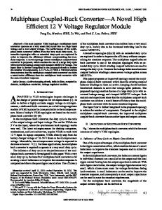
Built System Model in Simulink Analyse and Optimise the System Design (Speed, Power, Area) Elaborate Design for FPGA/ASIC Generate HOL from Simulink Model Verify HDL (Cosimulation/Hardware-in-the-Loop)
HDL (VHDl/Verilos)
FPGA
ASIC
Fig. 3. Method to generate HDL Code from MATLAB and Simulink, with code verification.
difficult aspect of implementing an algorithm on an FPGA. The real HDL code generation process starts by modeling the algorithm in MATLAB Simulink using a HDL Coder library of more than 200 blocks (MATLAB keeps on updating and adding new blocksets) or Stateflow. The components and blockset supported in HDL Coder can be found by typing hdllib in the command window. Fig. 3 shows the code conversion and verification process in MATLAB Simulink HDL Coder. Once the Simulink model is created, HDL Workflow Advisor guides in a step-by-step process to generate code from the model. Moreover it helps to check various other parameters and setting that is required for optimal code generation and verification. Ill. IMPLEMENTATION OF MODEL BASED DESIGN
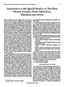
The implementation of HDL Coder in power electronics and drives is demonstrated by implementing a SVPWM modulation technique in a 3- VSI for generic applications. SVPWM refers to a special way of determining the switching sequence of the upper three power transistors of a 3- VST. It generates less harmonic in the output voltages and or currents in the windings of the motor load, possibility to optimize for lower switching losses, provides more efficient use of DC supply voltage as compared to direct sinusoidal modulation technique (voltage utilization of SVPWM is 2/..J3 times the sine wave) and compatible with the digital controller [19]. The circuit model of typical SVPWM modulated 3- VST is shown in Fig. 4. Switches SI to S6 are six power switches controlled by switching variables SWI, SW2, SW3, SW4, SW5, SW6 that shapes the 3- output voltage.
TT. CODE CONVERSION: MATLAB ISIMlJLINK TO VHDL CODE
HDL describes electronics circuits in terms of the circuit's operation, design, and tests to verify its operation by means of simulation. At the first step of code conversion process, the new design ideas and algorithms are represented in terms of mathematical models and are tested in MATLAB/Simulink floating point data types. However, implementation of control algorithms in FPGAs and ASICs require fixed-point data type conversion to reduce hardware resources. This conversion process often introduces quantization errors. As a consequence, a signal scaling and word-length optimization becomes a
Vdc
Fig. 4. SVPWM controlled VSI
572
D ufix24 En24 T1
T1
T1,T2,T0I2
, t,= If-ls : t,= IOns �:�
�;2
Scope1
1
4 En24 boolean
SW1
CD
SW2
ufix24 En24 TO/2
boolean
SW3 SW4
boolean
ufix24 En24
Is
to automatically generate HDL Code for FPGA prototype. Free-Running
The upper and lower switch of same leg is complement to each other to avoid shoot-through, which damages the switches. A dead-time is nonnally generated to avoid gating overlap when nearly coincident transitions take place at the upper and lower switch of same leg. This can be achieved either by implementing dead-time during FPGA programming, or using a MOSFET driver with inbuilt dead-time. Nowadays, MOSFET drivers come with inbuilt dead-time and fault shutdown capability [20], so it reduces the programming complexity and resource requirements of FPGA implementations. In SVPWM the reference voltage is mapped into switching space vector diagram and the duty cycles of the switches are calculated based on the mapping. There are six active states (VI, V2, V3, V4, V5 and V6) and two zero states (VO and V7) which combined in a various ways to generate the output voltage. Fig. 6 shows the basic switching vector and sector of SVPWM techniques. Fig. 5 shows the final MATLAB Simulink multirate model of SVPWM algorithm that automatically generates the HDL code for the FPGA prototype. The sampling rate of the model before the rate transition block is 1 flS, and IOns after the rate transition block, for a master clock speed of 100MHz. The switching frequency of the inverter is determined by: f Master Clock Speed (I)
[VdVq]
2
= '3
[I
-1/2 -1/2 -13/2 - -13/2
0
[] V1�:
(2)
abc-dq transformation is modelled in Matlab/Simulink as shown in Fig. 7. The bloksets are HDL Coder compliant with fixed point output. The word length for each block is shown in the signal path. sfix12_En4 means the data is signed 12 bit word length with 4 bit fraction length and ufixlO_En8 means the data is unsigned 10 bit word length with 8 bit fraction length. The operators, constants and blocks support different data types and representation of data is transparent to designers in each signal path. Details on how to convert floating to fixed point will be discussed in Section TV.
B. Determine �4 and Angle (0.)
For small switching time period Ts, Vrej can be considered approximately constant and can be expressed as (3) 2 ) r� d2 +
V . �(V V =
and, angle
a
=
tan
-,
(l VVdq J
q
(4)
Fig. 8 shows the implementation of above mathematical expression in fixed point simulink blocks. Ready to use Cartesian2Polar block in Simulink is not supported by HDL Coder, so the above equation to calculate instantaneous atan function is implemented in floating point s-function MATLAB code and then converted to fixed point.
=
2"
Where, n-m-bit free counter. For example, if n=12, 1 J;=100xIQ6/2 2=24.4lkHz. The details of the each blockset is described in the following sub-sections.
U1 U2
A. Transformation of abc-dq Reference Frame The voltage equations in the abc reference frame is transformed to the dq reference frame that consists of the horizontal (d) and vertical (q) axes. The relation between these two reference frames is
+
SW6
To
Fig. 5. Final SVPWM model in Matlab Simulink using HDL Coder
SW5
CD
sfix12 sfix12
Vd
U3
sfix12
Product5 C1
q Vq
sin(4pi/3)
Fig. 7. Inside abc2dq transformation block. V4(01l) (-2/3,0)
�_����--'::'.L-� .•d
Vl(lOO) (2/3,0)
D
V5(001) (-1/3,-1/V3)
V6(101) (1/3,-1/V3)
Fig. 6. Switching map of SVPWM for thee phase VSI
sfix24 En14 '01
-----ne
"'sfi""2 ' 4o.E 4 ---1-___ . 0 "" "" GD
573
'02
�
ufiX24 EnS .
Add
.J
UfiX24 En12.,
Sqrt
sfix24 En14
atan2JIXPI Cordie
Fig. 8. Determination of Vref and Angle (a)
m Vref
C. Determine Switching Time Duration (Tib Tn I], To) The instantaneous time duration of switching vector (T",Tn+1,To) for six switches are calculated in terms of a reference voltage (Vrer), angle (a) , switching time period (Tz), input voltage (Vdc) and sector (n). For the volt-second balance in sector-I, from Fig. 6, ->
Tl V"
SO, T
L
I;�f
rl �
e
co: : :
->
i
=
->
(
� v,.J,lI ::: i)tJ � v J e
h} 2
(5)
T,V, + T,V,
�
2
�.T2
cos
(6)
[ t)] e cost "3)
(7)
Tz =1; +T2 +To Solving §5, §6 and §7 we get, v'3T/ lv,,! I . ff 7;
And
Vdc
To-
=
sm(--a) 3
(8)
I smeal .
(9)
v'3T/ Iv,.,! vd,.
Hence, switching time duration in any sector n n-I fJJ�lv"1 I sm\ fJJ�lv"1 I sm( . -ff -a+-ff)= . )1 .. =--I --Jr)cosa-cos "
v�.
3
3
·
v�.
(
� 3
.
) )
v"31�lv�f I. n-J fJJ�IV�f I . n-J . n-J Tn+! = --- sln(a--;r)= --- -cosaSlll-JT+smaCOS-ff 3 v'k 3 3 v" And '0, Where,
=
Tl -
(T"
+
(
Sector T,
51
-Jr)sma
s
Fig. 10. Determination of sector (n)
T,al)
(10)
Sector
0° Sas 600
1--f--'.-'--+-+-+--I-,.,
51
II:
I
Sector
600 Sa S 120°
I--H-'--+---'-+_,.,
53 :_+-1-+--+-+-,-,-_ :53
I
T'l
51
vo Vl;V2; V7 i V7 V2! V< vo TO/2 n:12:To/2:TO/2 12:Tl:TO/2
_l:r -+h --L:-+_,.,S5
(12)
1
_�,fs-+ switching frequency of the VST
T1 - J:
51 53
Sector
T,
T,
1
-,--,- _ : :_H-,--+-+
51
vo VS: V4: V7 i V7 V4:VS: vo TO/2 T2iTliTO/2iTO/2 TliT2iTO/2
v:
J
i
i
I
Sector J
51
S3 L
I
55
T'l
---,I-,--+T---I i
I
VO !V3!V4 V7 i V7 :V4:V3 vo TO/linin TO/2ITo/2 [ n [n TO/2
T,
vo ;vs V6: V7 V7 :V6 vs; vo TO/2iTl T2:TO/2 TO/2:T2 Tl:TO/2
: 120° � as 1800
�
1--
2400 � a � 3000
I-N
53
551--f--'.-'--+-+-,--I-,.,55
i
T, i
J
VI
: 3000 � a � 3600 T,
-i-ii i
L
VO iVl;V6 V7 i V7 iV6 i vl VO TO/2:T2:Tl TO/2!TO/2:Tl:T2 TO/2
Fig. 11. Space Vector PWM switching patterns and corresponding switching
D. Determine the Sector (n) It is necessary to determine the location of the reference voltage (which is rotating at co = 2nf) to exactly generate the instantaneous duty cycle of each switch and switching sequence. The sector determination is implemented with compare to constant logic as shown in Fig. 10.
T
vo !V3 V2; V7 V7 ;V2 V3! VO TO/2;T2 n:To/2 TO/2:n T2:TO/2
III
....-+--+ .. i
53
551--+--"'-'--+ --+__,., 551--......
(11)
Fig. 9 shows the implementation of above mathematical expression for Tn,Tn+],To in fixed point Simulink blocks.
E.
I:
time at each sector.
U3
Determine the Switching Time of Each Power Switch
The switching pattern, sequence and time period of high side switch is determined based on the location i.e. angle (a) and magnitude of reference voltage (Vref) as shown in Fig. 11. The switching pattern and time is implemented for high side switch TA as shown in Fig. 12. Similar implementation is for TB and TC.
ufix24 En24 U4
TA
Fig. 12. Determination of the switching time of high side switch TA
IV. FPGA PROGRAMMING
A. Floating Point to Fixed Point Conversion
Fig. 9. Determination of switching time duration (Tn,Tn+"Tll)
Fixed point algorithm is implemented in FPGA for power, perfonnance and cost reasons. However, conversion from floating point to fixed-point is very challenging and time consuming, typically demanding 25 to 50 % of the total design and implementation time. In a fixed point domain a pair (w, F) 574 is considered for each of the parameter in algorithms, where W
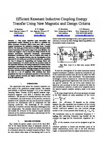
is word length and F is fraction length of the parameters. Large Wand F result in better performance and lower Bit Error Rate (BER) but design consume large resources in FPGA or implementation requires expensive FPGA. On the other hand, smaller Wand F result in large BER whereas smaller footprint. Optimization of wordlength to achieve best performance is an interactive process with the user in a MATLAB fixed point advisor which guides through the steps of converting floating point to fixed point algorithm. It also verifies the generated fixed-point code by comparing the floating and fixed point result. Multiple iterations by adjusting the word length settings, individually modifYing the data types as desired or accepting the 'proposedfixed-point types' as recommended by fixed-point advisor are required to meet the desired accuracy (low BER) and optimum fixed point design. Fig. 13 shows the control signal of SVPWM generated by both floating and fixed point design and the corresponding error. The peak conversion error is ±1.5%. This error should be kept minimal to utilise the full modulation range or the DC link voltage.
Vc Vy Vb
Fig. 14. Co-simulation scenario using ModelSim
�Em-m: I I I I I I: I I I I : I I I : I I I I 1:1 I ciTT1 � II I I I I I: I I I I I I: I I I I: I I I : I I I I I :I I I I I I I �I I [I � � i � [DJDdJ[[JJ�DDD[-100JOOci-DDJDrl �h::rDD[bDJ[DOtOJ-[ 0:0 [DO --:00 [ 0 0 0 :- J n [ � � I � I I I I I I: I I I I: I I: I I :I I: I I I I I I �h::TI 1 1: 1 1:1 1 :11 :1 1 :::rr::m1
B. Code Conversion (from *. mdllslx and *. mfiles to VHDL) The HDL Workflow Advisor in HDL Coder automatically converts MATLAB code (*. m files), Simulink (*. mdllslx files) from floating-point to fixed-point and generates synthesizable VHDL and Verilog code. MATLAB generates thousands of lines of VHDL codes in separate files for each blocksets. The generated code can be traced bidirectional to/from MATLAB and Simulink model. The HDL Workflow Advisor also highlights critical path timing in Simulink to help identifY speed bottlenecks and improve the performance of the design.
o
C. Verification
ms
• III 0.00000
1) HDL co-simulation: The HDL Coder generates VHDL and Verilog test benches using HDL co-simulation wizard that automatically connects to the HDL simulator e.g. Cadence Incisive, Mentor Graphics ModelSim and Questa for rapid verification of generated HDL code. Fig. 14 shows the co simulation scenario using Mentor Graphics ModelSim (student version). This co-simulation streamlines the verification process and helps to fix the error before hardware implementation. Fig. 15 shows the co-simulation results of SVPWM MATLAB and Simulink model with ModelSim RTL-Ievel models. The model was simulated for 3ms and it was found that the two results are exactly same.
I
I
I
I
I
0.5
1
Time [ms]
2
2.5
ms
IIII IIII 0.5
1.5
IIII 1
ms
IIII
ms
IIII IIII 1.5
IIII 2
ms
IIII
Time [ms]
ms
b) Mentor Graphics ModelSim
2) FPGA in-the-loop (FIL) co-simulation: FIL test the design in real hardware for the generated HDL code. It generates a Simulink FIL block as shown in Fig. 16 that represents the HDL code. The programming file is loaded onto an FPGA with JTAG connection. TX/RX of data from Simulink to FPGA is via gigabit Ethernet crossover cable that co-simulate and verifies the design in real time environment. It helps to detect, isolate, identify and resolve bugs in the early stages of design process.
S\lPWM_SimulinkMm
ce_out sw1
c)
s'tO. vy
!l,;
sw3
FIL
sw4 sw5
vb
sw6
Fig. 13. SVPWM control signals generated for one cycle (50Hz) by conversion % Error.
IIII 3
b)
b)
a) Floating-Point Design; b) Fixed-Point Design and c) corresponding
ms
IIII IIII 2.S
Fig. 15. Co-simulation results of SVPWM a) MATLAB Simulink model with
SVPWM M�
0)
3
SVPWMJIL
575
SCq:€2
Fig. 16. FPGA in-the-loop co-simulation
D. VHDL to bitstream and FPGA programming The generated HDL code is bit-true, cycle-accurate and synthesizable HDL code which is free from bugs. HDL Coder offers integration with Xilinx ISE design suite that makes it easy to implement algorithm in MATLAB and Simulink to target Xilinx FPGAs. Xilinx ISE compiles and generates the bitstream file which is then loaded into the FPGA using JTAG via the USB connection by iMPACT or Digilent Adept software. Table 1 shows the Xilinx ISE13.4 compilation report of resources utilization for SVPWM implementation in Spartan-6 XC6SLX45.
Ch 1 Freq 12.52kHz
Ch2 Freq
12.S1kHZ
V. EXPERIMENTAL RESULTS AND DISCUSSIONS
i1�� 800. OOOI'S PreVu
�
R-i
__
.. .. .. ........ . .. ................ ....
0 ___[",-:... ) ����c='
· UfJfJ�;;��it;h g�t�;igJ1�i
:/ ..
,-
DC·'
>d T �2f1S
� Lower switch gate signal
Ch4
M 4.00)JS
5.00 V
A ell 1 I-10.OmV
u-+"..... 194.84QJls
Fig. 17. SVPWM gating pulse from Spartan-6 FPGA for high side switch (Chl---7SWI. Ch2---7SW3. Ch3---7SW5. Ch4---7SW6)
16Jan 2013 13:33:09
Chl Freq 50.12 Hz
(Xilinx ISE13.4 estimated values)
54576
2%
Number of Slice LUTs
6117
27288
22%
Number of fully used LUT-FF pairs
1460
6178
23%
10
218
4%
I
16
6%
Number of bonded lOBs Number of BUFG/BUFGCTRLs Number of DSP48Als Number used as Memory
Ch2 Freq 49.96 Hz
Used Available Utilization 1521
21
58
36%
3
6408
1%
28 sep 2012 17:31:26
b)
Table I: Device utilization summary of Spartan-6 XC6SLX45
Number of Slice Registers
14:33:41
a)
The FPGA based approach to the automatic generation of VHDL code for digital controlled power electronics and drives using MATLAB Simulink is verified by implementing SVPWM modulated VSI in a Xilinx Spartan-6 platform. The six driving pulses from FPGA are connected to signal amplification and isolation circuit via 8 pin PMOD connector. The power ground and logic ground are completely isolated from one another using HCPL2531 optoisolator. It protects FPGA from circulating ground current and high voltage spikes (15kV/flS). Fig. 17(a) shows the FPGA generated SVPWM control pulses for the high side switches. Six SPW47N60C3 Cool MOS power MOSFET with best R1JS(on) are used for better efficiency design. The TTL level SVPWM signal from FPGA is amplified to meet the gate drive voltage requirement of the switch (±20V) by driver IC IR2130 from International Rectifier. It is a three phase high voltage bridge driver IC with three independent high and low side referenced output channels and has protection against fault [20]. The IR2130 also provides dead-time control to avoid any shoot-through to protect the switches. A dead-time (Td) of 2fls is introduced between high and low side switch as shown in Fig. 17(b). Too short dead time (Td3flS) increases THD, negatively impacting the power quality. The three phase line-to-line voltage of the VSI before filter is shown in Fig. 18(a) and Fig. 18(b) shows the filtered output voltage of the inverter. Small filter inductor (1.5mH) and capacitor (1.5flF) is required to filter out the switching harmonics. The THD of output voltage is only 3.8% and Crest Factor is 1.52, well below the IEEE allowable limits for grid connected inverter design or for motor drives application. The standby power loss is only 0.25% of rated power of the inverter (lkW).
Logic Utilization
13sep 2012
0....",. , 9.7600ms
16Jan 2013 14:10:23
b) Fig. 18. Three phase voltage out from the VSI without loading
576
a) before filter. b) after filter (Measured with high voltage differential probe GE8115 with attenuation of 1000:1. Chl-7VRy• Ch2-7VyB• Ch3-7VBR)
--
1l]!i2l�!Hl!rn!m1ID) [I][(l!l[I][I][(JiI[I1l[[!i
Scoing. AVG •
Lne FilterFreq Filter-
Tire
Integ: Reset -----:--:--
'IQ«)(»WA..
REFERENCES
�r. �:m �� (J':3
[I]
Concettina Buccella and Carlo Cecati, "Digital control of power converters -A survey", IEEE Trans. Industrial Informatics, vol. 8, no. 3, pp. 437-447, August 2012.
[2]
Stephan Van Beek
and Sudhir Sharma,
MathWorks,
"Four Best
Practices for Prototyping MATLAB and Simulink Algorithms on FPGAs", Verification Horizons, pp. 49-53, August 2011. [3]
Kiran Kintali and Yongfeng Gu, Model-based design with Simulink, HDL Coder, and Xilinx system generator for DSP," Mathworks White Paper 92077VOO, 2012.
[4]
Eric Monmasson, Marcian N. Cirstea, "FPGA design methodology for industrial
control
systems
-
A
review",
IEEE
Trans.
Industrial
Electronics, vol. 54, no. 4, pp. 1824-1842, August 2007. [5] 16 15 14
.. -
l.t.date 23784 ( 50r1sec)
Miro
Milanovic,
Mi�ja
Truntic
and
Primoz
Slibar,
"FPGA
implementation of digital controller for DC-DC buck converter",
-6.000 A -'.000 � -6.000 A
Proceedings, Fifth IEEE International Workshop on System-on-Chip for
2013/03/14 18:49:57
FFF
Fig. 19. Three phase voltage (300V/div) and current (2A/div) with 3300
Real Time Applications, pp. 439-443, Banff, 20-24 July, 2005. [6]
The control circuit demonstrated in this paper is an open loop system. Complex feedback control system of power electronics and electric drives can be easily implemented using similar Matlab model based design as described in this paper. For example, power flow control, grid synchronization, variable speed drive (VSD), DC link voltage control etc.; however, it requires AID or DIA converters for proper data interface to FPGA and various peripheral sensors (e.g. voltage (V), current (I) or angular speed (m) etc.). Fig. 19 shows the performance of the inverter during loading condition. The inverter is loaded with a delta connected resistive load of 300[2 in each phase. The load voltage and current shows a good performance of the inverter under loading conditions as well
Eftichios Koutroulis, Apostolos Dollas, Kostas Kalaitzakis, "High frequency pulse width modulation implementation using FPGA and
resistive load in each phase (delta connected).
CPLD ICs", J. Systems Architecture, vol. 52, pp. 332-344, June 2006. [7]
Lars T. Jakobsen and M. A. E. Anderson, "Digitally controlled point of load converter with very fast transient response", Digest, 12th European Conference on Power Electronics and Applications, pp. 1-10, Aalborg, 2-5 September, 2007.
[8]
Diego Puyal, Luis A. Barragan, Jesus Acero, Jose M. Burdio and Ignacio Millan,
"An FPGA-based digital modulator for full-or half:
bridge inverter control", IEEE Trans. Power Electronics, vol. 21, no. 5, pp. 1479-1483, September 2006. [9]
Ying-Yu Tzou and Hau-Jean Hsu, "FPGA realization of space-vector PWM control IC for three-phase PWM inverters", IEEE Trans. Power Electronics, vol. 12, no. 6, pp. 953-963, November 1997.
[10] J. Tian, G. Berger, T. Reimann, M. Scherf, J. Petzoldt, "Design and implementation of a FPGA-based controller for resonant inverters", IEEE Trans. Power Electronics, vol. 12, pp. 953-963, November 1997. [11] Angel de Castro, Pablo Zumel, Oscar Garcia, T. Riesgo and 1. Uceda, "Concurrent and simple digital control of an AC/DC converter with power
factor
correction
based
on
FPGA",
IEEE
Trans.
Power
Electronics, vol. 18, no. I, pp. 334-343, January 2003.
VI. CONCLlISIONS
We have described a method to facilitate the development and implementation of FPGA-based digital controllers in power electronic converters and drives. The method is faster and provides a greater degree of confidence than traditional manual HDL coding. To illustrate the method a laboratory prototype of a 1kW FPGA-controlled Voltage Source Inverter (YSI) was described in detail in which the fixed-point control algorithm was automatically generated from Simulink models using the MATLAB HDL Coder, and verified before implementation on a Xilinx Spartan-6 XC6SLX45 board. Experimental characterization of the resulting YSI converter resulted in 3.8% total hannonic distortion and line-to-line crest factor of 1.52, well within the allowable range of IEEE standards. The very close agreement between experiment and simulation shows the efficacy of the method. The method is expected to be particularly useful for prototype development of other power electronic converters and electric drives with more complicated interfacing and control algorithms. ACKNOWLEDGEMENTS
[12]
Oscar Garcia, Pablo Zumel Angel de Castro and Jose A. Cobos, "Automotive
DC-DC
bidirectional
converter
made
with
many
interleaved buck stages", IEEE Trans. Power Electronics, vol. 21, no. 3, pp. 578-586, May 2006. [13] Oscar Lopez, Jacobo Alvarez, Jesus Doval-Gandoy,
Francisco D.
Freijedo, Andres Nogueiras, Alfonso Logo and Carlos M. Penalver, "Comparison of the FPGA implementation of two multilevel space vector PWM algorithms", IEEE Trans. Industrial Electronics, vol. 55, no. 4, pp. 1537-1547, April 2008. [14] R. Erikson, S. Angkititrakul and K. Almazeedi, "A new family of multilevel matrix converters for wind power applications: Final report", NREL Report NRELlSR-500-40051, December 2006. [15] Marcian N. Cirstea and Andrei Dinu, "A VHDL holistic modeling approach and FPGA implementation of a digital sensorless induction motor control scheme", IEEE Trans. Industrial Electronics, vol. 54, no. 4, pp. 1853-1864, August 2007. [16] Da Zhang and Hui Li, "A stochastic-based FPGA controller for an induction motor drives with integrated neural network algorithms", IEEE Trans. Industrial Electronics, vol. 55, pp. 551-561, Feb. 2008. [17] Mohamed Wissem Naouar, Ahmad Ammar Naassani, Eric Monmasson and IIhem Slama-Belkhodja, "FPGA-based predictive current controller for synchronous machine speed drive", IEEE Transactions on Power Electronics, vol. 23, no. 4, pp. 2115-2126, July 2008. [18] Frede Blaabjerg, Philip C. Kjaer, Peter Omand Rasmussen and Calum
This work was supported by the Australian Research Council (ARC), Triquint Semiconductor Inc. USA, and [19] Macquarie University, Australia. The authors would like to thank Yokogawa for the loan of a WTl800 power analyzer; and Sudeshna Bhattacharya (Application Support Engineer, [20] MathWorks) for model verification (FIL) and Daryl Ning (Senior Application Engineer, MathWorks) for providing577 valuable comments and suggestions.
Cossar,
"Improved
digital
current
control
methods
in
switched
reluctance motor drives", IEEE Transactions on Power Electronics, vol. 14, no. 3, pp. 563-572, May 1999. Richard Zhang,
"High
nonlinear
unbalanced
and
performance
power
load/source",
converter PhD
systems
Thesis,
for
Virginia
Polytechnic Institute and State University, 17th Sept. 1998. International Rectifier, Data Sheet No. 60019 Rev. P, "IR21301IR2132 3-phase
bridge
driver",
info/datasheetsl datalir213O.pdf
http://www.irfcom/product-