H. I. A.li, Member IAENG, S. B. Mohd Noor, M. H. Marhaban, S. M. Bashi. Abstract-- In this paper a new method based on a particle swarm optimization (PSO) ...
Design of H-inf Controller with Tuning of Weights Using Particle Swarm Optimization Method H. I. A.li, Member IAENG, S. B. Mohd Noor, M. H. Marhaban, S. M. Bashi
Abstract-- In this paper a new method based on a particle swarm optimization (PSO) algorithm for tuning the weighing functions parameters to design an H controller is presented. The PSO algorithm is used to minimize the infinity norm of the transfer function of the nominal closed loop system to obtain the optimal parameters of the weighting function. This method is applied to a typical industrial pneumatic servo actuator with system uncertainty and wide range of load variation to illustrate the design procedure of the proposed method. It is shown that the proposed method can simplify the design procedure of H control to obtain optimal robust controller for pneumatic servo actuator system. Index Terms—Robust control, PSO, H control, Pneumatic actuator, parametric uncertainty.
I. INTRODUCTION H is one of the best known techniques available nowadays for robust control. It is a method in control theory for optimal controller design. Basically, it is an optimization method that takes into consideration a strong definition of the mathematical way to express the ability to include both classical and robust control concepts within a single design framework. It is known that H control is an effective method for attenuating disturbances and noise that appear in the system. It is one of the best techniques in linear control system. The “H” stands for Hardy space. “Infinity” means that it is designed to accomplish minimax restrictions in the frequency domain. The H norm of a dynamic system is the maximum amplification that the system can make to the energy of the input signal [1, 2].
Manuscript received January 26, 2010. H. I. Ali. is with the Electrical and Electronic Engineering Department, University Putra Malaysia, Serdand, Selangor, Malaysia, (corresponding author to provide phone: 0060-17-2579348; fax: 603-8946-6327; e-mail: hazemcontrol2001@ yahoo.com). S. B. Mohd Noor, is with the Electrical and Electronic Engineering Department, University Putra Malaysia, Serdand, Selangor, Malaysia, (email: samsul@ eng.upm.edu.my). S. M. Bashi, is with the Electrical and Electronic Engineering Department, University Putra Malaysia, Serdand, Selangor, Malaysia, (email: senan@ eng.upm.edu.my). M. H. Marhaban, is with the Electrical and Electronic Engineering Department, University Putra Malaysia, Serdand, Selangor, Malaysia, (email: hamiruce@ eng.upm.edu.my).
One of the most important parts and a key step in the design of the H controller is the selection of weighting functions and weighting gains for specific design problems. This is not an easy procedure and often needs many iterations as well as fine-tuning. Furthermore, it is hard to find a general formula for the weighting functions that will work in every case. Therefore, to obtain a good control design it is necessary to use suitable selected and tuned weighting functions [3]. In this paper, a method for the position control design of a pneumatic servo actuator system-using H controller is presented. The PSO algorithm is used to find the optimal values of the parameters of the weighting functions that lead to obtain the optimal H controller by minimizing the infinity norm of the transfer function matrix of the nominal closed loop system. The PSO method is used because of its simplicity and ease of implementation. The structured (parametric) uncertainty is considered in the design.
II. Particle Swarm Optimization Algorithm (PSO) PSO is one of a powerful optimization method with high efficiency in comparison to other methods. The PSO mechanism is initialized with a population of random solutions and searches for optima by updating generations. The potential solutions of PSO are called “particles”, fly through the problem space by following the current optimum particles. Each particle keeps track of its coordinates in the space of the problem, which are associated with the best solution (best fitness) it has achieved so far. The best particle in the population is denoted by (global best), while the best position that has been visited by the current particle is denoted by (local best). The global best individual connects all members of the population to one another. That is, each particle is influenced by every best performance of any member in the entire population. The local best individual is seen as the ability for particles to remember past personal success. The particle swarm optimization concept involves, at each time step, changing the velocity of each particle towards its global best and local best locations. The particles are manipulated according to the following equations of motion [4,5, 6]: (1) vik 1 h vik c1 rand ( xib xik ) c2 rand ( xig xik ) xik 1 x ik v ik 1
(2)
where vik is the particle velocity, xik is the current particle position, w is the inertia weight, xib and xig are the best value and the global best value, rand is a random function between 0 and 1, c1 and c 2 are learning factors. The PSO requires only a few lines of computer code to realize PSO algorithm. Also it is a simple concept, easy to implement, and computationally efficient algorithm [7, 8].
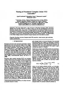
III. PNEUMATIC SERVO ACTUATOR MODEL Consider the pneumatic servo actuator system given in [9, 10]. This system is widely used in industrial applications because it is cheap, clean, lightweight, easy to maintain and it provides a high degree of compliance. On the other hand, it is difficult to achieve precise position for such systems because of the friction forces and the nonlinearity due to the compressibility of the air. Further, the variation in thermodynamic conditions causes an uncertainty in a number of model’s parameters. Therefore, it is a need to apply the robust control techniques to control such as systems. Fig. 1 shows the schematic diagram of the pneumatic servo actuator. The source of power used in this type of actuator is compressed air supplied to the jet pipe, and distributed between the two ways pneumatic cylinder as the jet pipe turns [11, 12]. The valve and actuator characteristics can be linearized about the operating point (nominal point) to yield the following fourth order linear model of the open loop system: (3) y P ( s ) G p ( s )U ( s ) Gd ( s ) Fd ( s )
required response of the servo actuator, the relationship between control signal and valve can be approximated by a proportional gain as mentioned in [13, 14]. Fig. 2 shows the block diagram of the pneumatic servo actuator system. The frequency characteristic of the pneumatic actuator with all parameters uncertainty is shown in Fig. 3. These characteristics show that the system bandwidth decreases when the load increases, until the system becomes slower. Also the phase margin decreases when the load increases and this makes the system to oscillate and be unstable system. IV. H CONTROLLER DESIGN WITH PARAMETRIC UNCERTAINTY The pneumatic servo actuator system can be represented as shown in Fig. 4. The parameters a, b and c can be assumed to be: a
fVo APo MVo , b , and c 2 K p KA pRT 2 K p KA pRT K p KRT
(6)
Supply pressure
PS
Jet pipe
Electrical control signal
Actuator Piston cylinder
where 2K
G p (s)
RTs A p
MVo 2 2 ( AP ) 2 Pi RTs La A p f RT L f s a )s ( s ( v s 1) s ( M MVo MVo MVo
Pb , Vb
)
P ,V
Chamber a aa
Chamber b
yP
(4) and Gd ( s)
Fig. 1. Schematic diagram of pneumatic servo actuator system.
1 M 2 ( AP ) 2 Pi RTs La A p f f RTs La )s ( s( v s 1) s 2 ( M MVo MVo MVo
)
(5) Input
where y p is the piston displacement, u is the valve input voltage, Fd is the disturbing load, K is the valve constant, A p is the piston area, Vo is the air volume, v is the valve time constant, R is the gas constant, is the specific heat
ratio, Ts is the temperature, f is the viscous friction coefficient. The nominal values of system parameters and their variation range are given in Table 1. The coefficient La is typically very small compared to other terms of the system and has a very small effect on the system performance. In particular, when under chocked flow conditions, La =0. The maximum mass flow rate occurs under chocked flow conditions and the unchecked flow rate is bounded by the chocked flow rate. Also, since the dynamics of the control valve are much faster than the
+
Amplifier
Polarized Relay
Output Actuator
-
Feedback Transducer
Fig. 2. Block diagram of pneumatic servo actuator system
Table I. The nominal system model parameters and their range Uncertain Parameter
m
2
R J kg.K
Vo (m 3 ) 10
Pi bar
0.005
287
f N.sec m
kg 10 3 s.V
0.1
50
3.2 3.4
4
1.5
Ts
M kg
2.5
3
1
60
4
4
5, 100
80
yd +
Magnitude (dB)
Minimum value Nominal value Maximum value
AP
-
-
K
K
293.15
1 a
KP V/m
1.4
400
yp
Phase (deg)
b c Fig. 4. Block diagram of pneumatic servo actuator system with its main parameters Frequency (rad/s)
Fig. 3. Frequency response characteristics of the system with parameters uncertainty and wide range of load variation.
1 1 1 p a a (1 p a a ) 1 Fu ( M a , a ) a a (1 p a a ) a a
with p a Ma p a
The three physical parameters a, b and c are unknown exactly, therefore, they can be assumed to be within the range of the system parameters in Table I, That is: a a (1 a p a ) , b b (1 b pb ) and c c (1 c pc ) (7)
where a 0.0664 10 5 and 0.1327 10 4 for small and wide ranges of load variation, respectively, b 0.1295 10 4 and c 0.01585 are the nominal values
of a, b and c. p a , pb and p c and a , b and
c
1 approach. The quantity ( ) can be represented as an upper a linear fractional transformation (LFT) in a as:
(9)
b Fu ( M b , b )
(10)
b b
(11)
c Fu ( M c , c )
(12)
0 Mc pc
(13)
with 0 Mb pb
the possible perturbations on these parameters. In this work we let p a 0.99999991 and 0.999246 for the two ranges 1 a , b , c 1 . Note that this represents up to 99.999991% and 99.9246% uncertainty in the parameter a, 64% uncertainty in the parameter b and 17.4% uncertainty in the parameter c. The three constant blocks in Fig. 4 have been replaced by block diagrams in terms of a , p a , a , etc., in a unified
1 a 1 a
Similarly, the parameters b and c can be represented as an upper LFT in b , and c as:
represent
of load variation, respectively, pb 0.64 , pc 0.174 and
(8)
and
with c c
Fig. 5 shows the representation of uncertain parameters as LFTs. The relationship between the input signals, w the output signals, z can be expressed as [1]:
ua yd +
z Fu ( N , ) [ N 22 N 21 (1 N11 ) 1 N12 ]w
(14)
-
ya
a
-
yb
represent a or b or c . The inputs and outputs of a , b and c are denoted as y a , y b , y c respectively, as shown in Fig. 6.
and
Mb
u a , ub , u c ,
yc
(15)
ub yb v M b y b p
(16)
Fig. 6. Block diagram of the pneumatic system with uncertain parameters
x1 x 2 x 2 x 3
u a a y a , ub b yb , u c c y c
(18)
The system state space representation can be expressed as: x1 y p , x 2 y p x1 such that x 2 y p x1 (19)
y
(20) (21)
1 (u vb vc ) a y a p b u b b x3
(17)
where
Mc
As a result, the following equations can be obtained:
u ac yc v M c y c p
u
uc
c
The equations relating all inputs to corresponding outputs around the uncertain parameters can be obtained as: ua ya v M a u v v b c a
yp
ub
b
where N may represent M a or M b or M c and may
Ma
x 3 p a u a
(22) (23)
vc pc u c c x 2 (24) The equations governing the pneumatic servo actuator system dynamic behaviour can be obtained as: 0 x1 0 x2 x 3 0 y a 0 y b 0 yc y 0 p 1
1 0 c a c a 0 c
0 1 b a b a b 0
0
0
0 0
0 0
0 0 pb a pb a 0 0
0 0 pc a pc a 0 0
0
0
0
pa pa
0 x 0 1 1 x2 a x3 1 u a a u b 0 u c 0 u 0
(25)
and u a a u 0 b u c 0
w
N
z
0
b 0
0 ya 0 y b c y c
(26)
Let G p denotes the input/output dynamics of the pneumatic system, which takes into account the uncertainty of parameters. G p has four inputs ( u a , ub , u c , u ), four outputs ( y a , y b , y c , y p ) and three states ( x1 , x 2 , x3 ).
Fig. 5. General LFT representation
The state space representation of G p is [2]: A G p C1 C 2
where
B1 D11 D21
B2 D12 D22
(27)
0 A 0 0
1 0 c a
0 0 1 , B1 0 b p a a
0 0 B2 0 , C1 0 1 0 a
c a 0 c
0 0 pa a
0 0 , pc a
s
b a b , 0
1 a 0 D11 0 , D12 0 , C 2 1 0 0 , 1 0 a D21 0 0 0 , D22 0 (28)
It is clear that the system matrix G p has no uncertain
closed loop system will be internally stable. Also, the required closed loop system performance should be achieved for the nominal plant G p . To obtain a good control design, it is necessary to select suitable weighting functions. The performance and control weighting functions formulas that have been used in this work are [15]:
a 0 0
0 b c
W p ( s)
0 0 0
(s 2 2 1 wc s wc 2 ) ( s 2 2 2 wc s wc 2 ) s2 2
(29)
with diagonal uncertainty matrix as shown in Fig. 7, where is the unknown matrix, which is called the uncertainty matrix with fixed structure (structured uncertainty).
(30)
where pb1 0 and selected to be 0.1, pb 2 is selected to be infinity. This is equivalent to simply shifting the jw-axis by pb1 units to the left. The H controller was obtained for the shifted system then it was shifted back to the right with the same units. The design requirements and objectives for pneumatic servo actuator system in this work is to find a linear, output feedback control u ( s ) K ( s ) y p ( s ) , which ensures that the
parameters and depends only on a , b , c , p a , pb , pc and on the original system parameters. The uncertain behaviour of the original system can be described by the upper LFT representation as: y p Fu (G p , )u
sˆ pb1 sˆ 1 pb 2
Wu ( s )
wbc
s
Mu
w 2 bc Mu
(31)
(32)
s 2 2 wbc s w 2 bc
where is the d.c. gain of the function which controls the disturbance rejection, is the high frequency gain which controls the response peak overshoot, wc is the function crossover frequency, 1 and 2 are the damping ratios of crossover frequency, wbc is the controller bandwidth, M u is the magnitude of KS , and is a small value.
u
G p (s )
y
Fig. 7. Upper LFT representation of the system
B. CONTROLLER DESIGN The H controller was designed so that H -norm from e input w Fd to output z p is minimized. eu eu Wu(s)
A. Bilinear Transform and Weighting Functions Selection Since the proposed system has jw-axis pole, the H controller, if it is reliably computed, would have a marginally stable closed loop pole at the corresponding jwaxis location. This problem leads to singularities in the equations that determine the state space realization of H control law. Therefore, a simple bilinear transform has been found to be extremely useful when used with robust control synthesis. This transformation can be formulated as a jwaxis pole shifting transformation [15]:
dist Fd
Gd(s) r=0
u
Gp(s)
+
ep
+
-
e
Wp(s)
K(s)
Fig. 8. The standard feedback diagram of the system with weights
Where Fd is the input disturbance signal, e p , eu are the weighted error and control signals. Fig. 8 shows the standard feedback diagram of the system with weights. The generalized plant P is expressed by: e p W p Gd e 0 u e Gd
W pG p F Wu d u G p
iv) c1 2 and c 2 2 . v) Maximum iteration is set to 100. The PSO steps for obtaining the optimal parameters of the proposed controller can be summarized as: 1. Define the system model, G p (s ) .
(33)
4.
5.
denoted as xig .
W G S Fl ( P, K ) p d Wu Gd KS
(34)
6.
The objective of H control is to find the controller K(s)
7.
that internally stabilizes the system such that T zw (s )
is the transfer function of the
W p Gd S = W G KS u d
(35)
The H control minimizes the cost function in equation (35) using -iteration [16] to find the stabilizing controller such that Tzw
Update the velocity of each individual according to (2). Update the position of each individual according to (1). If the number of iterations reaches the maximum, then go to step 9, otherwise, go to step 4.
is
system from input w to output z and can be expressed as:
Tzw
equations (31) and (32). Initialize the individuals of the population randomly in the search space. For each initial of the population (vector of the parameters to be optimised), determine the fitness function in equation (35). Compare each value of equation (35) with its personal best xi . The best value among the xi is
3.
where u is the control signal. The lower linear fractional transformation of the generalized plant P and controller K (s ) can be described by:
minimized [3]. Where Tzw
Define the structure of W p , Wu according to
2.
. To find the optimal value of , the
PSO algorithm was used to tune the parameters of the selected weighting functions. The weighting functions have a significant effect on the overall design of H control technique. The optimal value of is the infimum overall such that the H control conditions are satisfied. A suboptimal H controller was obtained using the following Matlab command:
>> [ K , Tzw , suboptimal ] h inf syn( P, n y , nu , min , max , tol )
8.
The latest xig is the optimal parameters of the
9.
weighting functions. The proposed PSO algorithm for obtaining the optimal values of the weighting functions parameters is described by the flowchart shown in Fig. 9. The overall block diagram of the system with PSO tuning algorithm is shown in Fig. 10. The interval for iteration was selected between 0.1 and 10. The obtained controllers for the two cases of load variation range, respectively, are: K (s)
K (s)
2.797 s 2 598.6 s 3.203 10 5 s 3 7035 s 2 2.422 10 5 s 3.222 10 6
(37)
2.021s 4 90.13s 3 6568 s 2 6.191 10 4 s s 2383s 5.195 10 4 s 3 4.236 10 5 s 2 1.444 10 6 s 5.588 10 4 5
4
(38) The optimal weighting functions parameters obtained with 0.8559 using PSO algorithm are shown in Table II.
(36) where n y and nu are the dimensions of y p and u, min
V. RESULTS AND DISCUSSION
and max are the lower and upper bound for optimal , and
Fig. 11 shows the singular values of the closed loop system with the controller K (s ) . As is seen, the maximum value of the closed loop system is less than one, that is, the
tol is the tolerance to the optimal value. The fitness function used in PSO algorithm is the performance criteria stated in equation (35). The algorithm obtains the minimum value of the infinity norm of the performance criteria from the search space that minimizes the objective function in equation (35). The following parameters have been used for carrying out the QFT controller design using PSO: i) The members of each individual in the PSO algorithm are , , wc , 1 , 2 , wbc , M u . ii) Population size equal to 100. iii) Inertia weight factor h 2 .
condition “ W p (1 G p K ) 1
1 ” has been satisfied. This
can be checked by computing the sensitivity function of the closed loop system and comparing it with the inverse of the performance weighting function as shown in Fig. 12. It is clear that the sensitivity function lies below the inverse of W p , which means that the performance criterion was satisfied. Fig. 13 shows the frequency response of the open loop uncertain system with the controller. From this plot, it can be seen that the minimum gain and phase margins that have been satisfied for the system with small and wide
ranges of load variation are 14.1 dB, 60.6 and 12.6 dB, 55.9 , respectively. This means that the system is stable with all parameters uncertainty, that is, the robust stability has been satisfied. The time response characteristics of the closed loop nominal and uncertain systems are shown in Figs. 14 and 15, respectively. From these figures it can be seen that the time response specifications that have been achieved for the two cases of load variation range are: rise time=0.239 s, settling time (2%)=0.498 s, maximum overshoot=10% for the case of small range of load variation and rise time=0.573 s, settling time (2%)=1.18 s, maximum overshoot =11% for the case of wide range of load variation. The time response characteristic of the system subjected to disturbance is shown in Fig. 16.
It shows that the disturbance attenuation specifications have been met. For practical requirements, it is required that the control signal be small to avoid the problem of saturation. Fig. 17 shows the frequency characteristics of the control signal where a small magnitude maximum value has been obtained. However, for discretizing the system and the obtained controllers, the Zero-Order-Hold and Bilinear Transformation methods were used, respectively. With a sampling time, Ts 0.02 s, the following discrete controllers for small and wide ranges of load variation were obtained, respectively: K ( z) K ( z)
Start
(39)
( z 0.9187)( z 2 1.371z 0.5036)
0.0011952( z 1)( z 1)( z 0.8083)( z 2 0.873 z 0.5826) ( z 0.9187)( z 0.8141)( z 0.9992)( z 2 1.771z 0.7925)
(40) Fig. 18 shows the discrete time response specifications of the controlled system.
Define the system model, Evaluate the objective function equation (35)
Gp
0.004131( z 1)( z 2 1.433 z 0.706)
ep Wp(s)
Define the structure of according to
W p , Wu
equations (31) and (32)
criteria satisfied
eu
PSO Tuning Algorithm
No 1
Wu(s) Fd
Yes Initialize randomly the swarm (position x and velocity v)
-
yd +
Set the best local
Gd(s)
Gp(s)
K(s)
+
yp
-
Initialize iteration, k
1
i> swarm size
Fig. 10. Block diagram of the overall controlled system
No
2
Table II. Optimal parameters of weighting functions
3 Yes Initialize swarm size, i
2 Update position equation (2)
Set the weighting functions then find the controller
Construct the overall system
H algorithm
Set the best global
Update velocity equation (1)
k> iteration
No
Parameter
Small range of load variation
Wide range of load variation
90.5
60.5
0.01
0.01
wc
5
4.93
1
1.38
0.38
2
8.12
8.1242
w bc
10.7
1.7
Mu
1
1.00112
3
Yes The optimal values in global best
Find K(s) by optimization
End
Fig. 9. Flowchart for tuning the weighting functions using PSO
Phase (deg) Magnitude (dB)
Magnitude (log scale)
Minimum G.M=14.1 dB
Minimum P.M= 60.6
Frequency (rad/s)
Frequency (rad/s)
(a)
Magnitude (log scale)
Phase (deg) Magnitude (dB)
(a)
Minimum G.M=12.6 dB
Minimum P.M= 55.9 Frequency (rad/s)
Frequency (rad/s)
(b) Fig. 13. Frequency response characteristics of the uncertain controlled system a) in case of small range of load variation b) in case of wide range of load variation
Piston displacement (mm)
Magnitude (log scale)
(b) Fig. 11. The largest singular Value of the closed loop controlled system a) in case of small range of load variation b) in case of wide range of load variation
--- W p 1 S
Time (s)
Frequency (rad/s)
--- W p 1 S
Frequency (rad/s)
(b) Fig. 12. Frequency characteristics of sensitivity function S and the inverse of the weighting function a) in case of small range of load variation b) in case of wide range of load variation
(a)
(a)
Piston displacement (mm)
Magnitude (log scale)
(a)
Time (s)
(b) Fig. 14. Closed loop time response characteristics of the controlled system in case of small range of load variation a) nominal plant b) uncertain plant
Magnitude (dB)
Piston displacement (mm)
Frequency (rad/s)
(a)
(a)
Magnitude (dB)
Piston displacement (mm)
Time (s)
Frequency (rad/s)
Time (s)
(b) Fig. 17. Frequency response characteristics of the control signal a) in case of small range of load variation b) in case of wide range of load variation
Piston displacement (mm)
Piston displacement (mm)
(b) Fig. 15. Closed loop time response characteristics of the controlled system in case of wide range of load variation with structured uncertainty a) nominal plant b) uncertain plant
Time (s)
(a)
Time (s)
Piston displacement (mm)
Piston displacement (mm)
(a)
Time (s) Time (s)
(b) Fig. 16. Time response characteristics of the closed Loop controlled system subjected to disturbance a) in case of small range of load variation b) in case of wide range of load variation
(b) Fig. 18. Discrete closed loop time response characteristics of the controlled system a) in case of small range of load variation b) in case of wide range of load variation
VI. CONCLUSION In this paper, an H controller was designed to assure robust stability and robust performance of the uncertain pneumatic servo actuator system with small and wide ranges of load variation. The H controller was designed using structured (parametric) uncertainty to achieve robust stability and performance of the system. The two cases of load variation range have been considered in the design. Suitable formulas for performance and control weighting functions have been selected for controller design requirements. The particle swarm optimization algorithm (PSO) was used to tune the performance and control weighting functions by minimizing the infinity norm of the transfer function matrix of the nominal closed loop system. The use of the PSO method simplified the design procedure to obtain the optimal robust controller, which achieves the position control of the pneumatic servo actuator system. Further, it can be concluded that the H optimal control is a powerful technique to design a robust control for the pneumatic servo actuator system with structured uncertainty and disturbances.
REFERENCES [1] [2] [3] [4]
[5]
[6]
[7]
[8]
[9]
[10]
[11]
[12]
[13]
[14]
[15]
D. W. Gu, P. Hr. Petkov, and M. M. Konstantinov, “Robust control design with Matlab”, Springer, 2005. S. Alok, “Linear systems optimal and robust control”, Taylor and Francis Group, USA, 2007. K. Zhou, and J. C. Doyle, “Essentials of robust control”, Prentice Hall, 1998. M. E. El-Telbany, “Employing particle swarm optimizer and genetic algorithms for optimal tuning of PID controllers: A comparitive study”, ICGST-ACSE Journal, Vol. 7, No. 2, 2007, pp. 49-54. A. A. El-Saleh, M. Ismail, R. Viknesh, C. C. Mark, M. L. Chen, “Particle swarm optimization for mobile network design”, IEICE Electronics Express, Vol. 6, No. 17, 2009, pp. 1219-1225. M. Nasri, H. Nezamabadi-pour, M. Maghfoori, “A PSO-Based optimum design of PID controller for a linear brushless d.c motor”, World Academy of Science, Engineering and Technology, Vol. 26, 2007, pp. 211-215.
H PID controller using particle swarm optimization”, International Journal of Control, Automation, and Systems, Vol. 7, No. 2, 2009, pp. 273-280. B. Allaoua, B. Gasbaoui, B. Mebarki, “Setting up PID d.c motor speed control alteration parameters using particle swarm optimization strategy”, Leonardo Electronic Journal of Practices and Technologies”, Vol. 14, 2009, pp. 19-32. M. Karpenko, N. Sepehri, “Development and experimental evaluation of a fixed-gain nonlinear control for a low-cost pneumatic actuator”, IEE Proc.-Control Theory Appl., Vol. 153, No. 6, 2006, pp. 629-640. H. I. Ali, S. B. Mohd Noor, S. M. Bashi, M. H. Marhaban, “Robust QFT controller design for positioning a pneumatic servo actuator”, Proc. of student conference on research and development, Johor, Malaysia, 2008, pp. 128-1—128-4. K. Khayati, P. Bigras, L. A. Dessaint, “Force control loop affected by bounded uncertainties and unbounded inputs for pneumatic actuator systems”, Journal of Dynamic systems, Measurement, and Control, Vol. 130, No. 011007, 2008, pp. 1-9. S. Qiang, L. Fang, “Two effective control algorithms for a pneumatic system”, International Technology and Innovation Conference, Hangzhou, China, 2007, pp. 1980-1985. Y. Zhu, “Control of pneumatic systems for free space and interaction tasks with system and environmental uncertainties”, Ph.D Dissertation, Vanderbilt University, Nashville, Tennessee, 2006. M. Karpenko, N. Sephri, “QFT design of a PI controller with dynamic pressure feedback for positioning a pneumatic actuator”, Proc. of of American Control Conference, Boston, Nassachusetts, 2004, pp. 5084-5089. R. Y. Chiang and M. G. Safonov, “Matlab robust control toolbox”, Mathworks, Inc., USA, 1997. M. Zamani, N. Sadati, M. K. Ghartmani, “Design of an
[16] Skogestad and Postlethwaite, “Multivariable feedback controlanalysis and design”, Wiley, 2005.
Hazem I. Ali was born in Baghdad, Iraq. He received the B.Sc and M.Sc degrees in Control and Systems Engineering from University of Technology, Baghdad, Iraq, in 1997 and 2000 respectively. From October 2002 to November 2007, he was a lecturer in the Department of Control and Systems Engineering, University of Technology, Baghdad, Iraq. Since 2008 he is a Ph.D student in the Department of Electrical and Electronic Engineering, Control and Automation Field, University Putra Malaysia, Malaysia. His current research interests include Robust control, Intelligent control, Process control.
Samsul Bahari bin Mohd Noor, graduated from University of Warwick in Electronic Engineering in 1991, and obtained his MSc and PhD in Control Engineering at Sheffield University, UK, in 1992 and 1996 respectively. He is a Senior Lecturer at the Department of Electrical and Electronic Engineering, Faculty of Engineering, UPM. He was the Head of IT unit and the Head of the Electrical and Electronic Engineering Department. Currently, he is a Deputy Dean (Development and Finance) of the Engineering Faculty and also Head of Control System and Signal Processing research area. He has been invited by the Ministry of Human Resources to develop the National Occupational Skill Standard for Process Control. He has led a few researches on Satellite Control, and Optimal and Intelligent Control of Chemical Processes, apart from being a member of research groups related to instrumentation and control. Senior Member of IEEE, Member of Technical Committee (SIRIM)( 2006-date). Areas of Expertise: Control engineering, process modelling and control and instrumentation, Model Predictive Control and Intelligent Control.
Mohammad Hamiruce Marhaban, received B.Eng. in Electrical and Electronic Engineering, Universiti of Salford, UK, from 1996 to 1998. He received Ph.D degree in Electronic Engineering, Universiti of Surrey, UK, from 1999 to 2003. He is a Lecturer in Department of Electrical and Electronic Engineering, Faculty of Engineering, UPM. (May 2003 to Present), and also he is a Member of IEEE. Area of Interest: Intelligent Control System and Computer Vision.
S. M. Bashi, graduated from University of Mosul, in Electrical and Electronics Engineering (1969). He received his PhD in Simulation of power transmission system from Loughborough University of Technology, England (1980). Since 1999, he is with the Department of Electrical and Electronics Engineering, Faculty of Engineering, Universiti Putra Malaysia, Malaysia. His area of research interest includes; power system analysis and design, quality of power supply, simulation and application of power electronics systems, and machines drives.