Kybernetika
Goshaidas Ray; Sitansu Dey; T. K. Bhattacharyya Design of reaching phase for variable structure controller based on Householder transformation Kybernetika, Vol. 41 (2005), No. 5, [601]--622
Persistent URL: http://dml.cz/dmlcz/135681
Terms of use: © Institute of Information Theory and Automation AS CR, 2005 Institute of Mathematics of the Academy of Sciences of the Czech Republic provides access to digitized documents strictly for personal use. Each copy of any part of this document must contain these Terms of use. This paper has been digitized, optimized for electronic delivery and stamped with digital signature within the project DML-CZ: The Czech Digital Mathematics Library
http://project.dml.cz
K Y B E R N E T I K A — V O L U M E 41 ( 2 0 0 5 ) , N U M B E R 5 , P A G E S
601-622
DESIGN OF REACHING PHASE FOR VARIABLE STRUCTURE CONTROLLER BASED ON HOUSEHOLDER TRANSFORMATION G O S H A I D A S R A Y , S I T A N S U D E Y AND T . K . BHATTACHARYYA
In this paper a design of reaching phase for variable structure controller with sliding mode of an uncertain dynamic system based on Householder transformation method is considered. The proposed method reduces the number of switching gain vector components and performs satisfactorily while the external disturbance component does not satisfy the matching conditions. Subsequently the stability of the global system is studied and furthermore, the design of switched gain matrix elements based on fuzzy logic approach provides useful result for smooth control actions. The efficacy of the proposed method is demonstrated by considering a load-frequency control problem of interconnected power system. Keywords: switching function, reachability, Householder transformation, variable structure control, fuzzy logic, interconnected power systems, Lyapunov function AMS Subject Classification: 93B12, 93C42, 93D05, 93D15
1. INTRODUCTION Variable-Structure Control (VSC) with sliding modes is widely recognized in control research community due to its insensitiveness to parametric uncertainties and disturbances [10]. Sliding-mode control design generally involves two main steps: firstly, the selection of a sliding surface which induces a stable reduced-order dynamics assigned by the designer, and secondly the synthesis of a switching control law to force the closed-loop system trajectories onto and subsequently remain on the sliding surface. It is powerful in controlling the system with bounded unknown disturbance and can provide very robust performance and transient performance [2, 3]. The system state trajectory in the period before reaching the sliding surface is known as the reaching phase in the control literature. A comprehensive guide on sliding-mode control for control engineers is given in [7] and most salient feature of variable structure sliding mode control is that it is completely robust to matched uncertainties. However, there are even more systems which unfortunately are affected by mismatched uncertainties and do not enjoy nice matching condition. Thus the system behavior in the sliding mode is not invariant to the mismatched uncertainty; the system performance can not be assured insensitive due to parametric uncertainties. Other remarkable advantages of sliding mode control approach are the
602
G. RAY, S. DEY AND T.K. BHATTACHARYYA
simplicity of its implementation and the order-reduction of the closed loop system [4]. Pole assignment or Linear Quadratic (LQ) techniques are often used as a component of sliding mode control. However, to be fair, one should also point out two foremost assumptions in the application of VSC with sliding mode control. First, most of the design techniques for sliding-mode control assume that all the system states are accessible to the control law and second, assume the possible occurrence of real sliding mode (chattering phenomena) instead of the ideal one. However, since a discontinuous control action is involved, chattering will take place and the steady-state performance of the system will be degraded. To overcome this problem, numerous schemes have been reported in the literature and one of the most common techniques to alleviate this drawback is to introduce a boundary layer about the sliding plane [9]. The basic idea consists of introducing a boundary layer of the switching surface in which the control law is chosen to a continuous approximation of the discontinuous function when the trajectory of system is inside the boundary layer. A robust sliding mode controller design based on the derivative of control instead of the control itself reduces the effect of chattering. However, the boundary approach provides no-guarantee of convergence to the sliding mode and involves a trade off between chattering and robustness. Reduced chattering may be achieved without sacrificing robust performances by combining the attractive features of fuzzy control with sliding mode control [1]. In this paper, we shall discuss how to design a reaching phase based on Householder method with a state-feedback control law. The control law consists of linear feedback term plus a discontinuous term, which guarantee that the sliding mode exits and is globally reachable under a very mild restriction. This paper extends the work of White et al.[ll] in order to design a simple sliding mode with variable structure controller based on Householder method. This in turn reduces the number of switching gain vector components as compared to White et al.[ll] method and moreover, for the non-switched gain vector components no additional inequality constrains are required to drive the state trajectory into the sliding surface. The significant advantage of the proposed method is addressed for full/reduced switching control gains. A fuzzy logic approach is also adopted in order to avoid hard switching control gains and subsequently the corresponding smooth control signals ensure the reaching conditions and decrease the reaching phase time. This paper is organized as follows. In Section 2, a mathematical description of the problem is given. Reaching phase design technique, based on Householder method is developed in Section 3. Subsequently, the stability of the sliding mode state trajectories is studied in the same section. In Section 4, design of an equivalent switch gain matrix based fuzzy logic approach is considered. In Section 5, the effectiveness of the proposed VSC control scheme based on Householder method is demonstrated by considering the load-frequency control problem of interconnected power systems. Section 6 provides a brief conclusion. 2. PROBLEM FORMULATION Consider a linear time-invariant system described by
Design of Reaching Phase for Variable Structure Controller ...
603
X(t)
=
AX(t) + BU(t)
(1)
Y(t)
=
CX(t)
(2)
where X(t) = state vector G 3? n x l , U(t) = input vector G 5Rmxl and Y(t) = output vector G 3fJpxl. It is assumed that the system is completely controllable. All the states are directly measurable and the linear system is assumed to be in regular form and the state equation (1) explicitly is described by following pair of equations: Xi(t) X2(t)
= =
AnXi(t) A2iXi(t)
+ Ai2X2(t) + A22X2(t)
+ B2U(t)
(3) (4)
where Xx(t) G ^ n " m ) x l , X2(t) G K m x l , B = [ 0 B2 } T and B2 G 9J m X m . If the original system is not in a form of equations (3) and (4), it is required to transform the system (1) into a regular form by using a linear transformation matrix [4]. Before we propose the new VSC based on Householder method, a brief discussion on sliding surface is given below. c = SX(t).
(5)
With no loss of generality, we can rewrite the equation (5) in more explicit form õ{ť) =
= HSаXа{t)
(24)
0 where Hmxm is the Householder transformation matrix which is symmetric and orthogonal. Differentiating equation (22) and using equation (23) we will obtain the following expressions t(t) =
HSaXa(t)
= HSa [AacXa(t)
- BaAKasXa(t)
+ BaV;
+ Barjp (*, Xa(t))
+ BaV;
+ fad]
= H diag [Ari, A r 2 , . . . , A r m ] • [5 a X a ] - [HSaBaAKasXa(t) (Note, SaAac
+ HSaBa(Vp*
+ Vf) + HSa(Bar]p(t,Xa(t)
+ fad)]
= diag [A ri , A r 2 , . . . , A r m ] Sa).
Now, a Singular-Value-Decomposition is employed on Sa which will convert the above equation in the following form a(t)
=
Hdiag [A rl , A r 2 , . . . , A r m ] [WDVTXa(t)] +HB2Vp* + HB2V;
[HB2AKasVVTXa(t)
-
+ HB2j]p (t, Xa(t)) + HSafad{t)] a r e
ls
where Wmxm and V(n+p)x(n+p) the orthogonal matrices and -D mX (n+p) the rectangular matrix with diagonal elements are the singular values (ai > a 2 > • • • > a m > 0) of Sa [8]. The main idea of using the Householder transformation technique is to obtain reaching phase conditions in a simpler form by exploiting the structure and properties of both D and H matrices and moreover, with a view to reduce the number of switching gain vector components. Using the properties of D and H, the above equation is rewritten as 9(t) = HDXa(t)
- AKasXa(t)
+ Vp + Vf + fj*p + fad
(25)
where H = H diag [ A r l
A r2
V) = HB2Vf*,
-..
A r m ] W,
AKa8
= HB2AKa8V,
% = HB2r,p (t, Xa(t)),
and the transformed state is given by Xa(t)
=
Tad =
VTXa(t).
Vp = HSafad
HB2Vp\
608
G. RAY,
S. DEY AND T.K, BHATTACHARYYA
The equation (25) can be rewritten in different form as m
Sift) = Yl {akHlk-~5Ks,lk)*a,k(t) к=l n+p
-
Ш
J2 j=m+l
0=
m k=l ~
*as,i^a,j(t)
+ V*pil +
V*f 0 and fj = 2.7J + 2fJ V (X(t)) < XT(t) {ATP + PA1
2aXT(t)LTBTPX(t)
T
(38)
+2pP + jQ-y- PBB P)X(t)
+
\m„(1'1PBBTP)
- (2p\mm(P) + j\min(Q))
+
_ >2" ll/Tll2l|P
11*11-"
\\x\\l
Examination of equation (39) revels that sufficient conditions for V < 0 are (A-aBL)тP BTP 2P\mm(P)
+ P(A-aBL)+чQ
+ j\mm(Q)
+ 2ßP T
> ±\mUPBB P)
PB 7І
< 0
+ J^pliP.
(39) (40)
612
G. RAY, S. DEY AND T.K. BHATTACHARYYA
It can be noted that the solution of LMI equation (39) along with the above additional condition ensures V < 0. Thus, we conclude that the sliding mode state trajectories of the uncertain system (15) and (16) under the equivalent control action (35) are robustly asymptotically stable. Thus, we have successfully developed a new constructive reaching phase design based on Householder method and subsequently the stability condition for completely uncertain system is established. Hence, the system is boundedly stable. • 4. REACHING MODE GAIN COMPONENTS (AKas FUZZY LOGIC APPROACH
{j)
BASED ON
Fuzzy logic control (FLC) has recently proved to be a successful control approach for complex system. It is well known that each control method always has its advantages and drawbacks, or we can say that all control techniques have their individual characteristic features. Combining several control theories to design a new controller may have possibly better system performance than one based on single control theory only. In this section, the design of switch gain control components based on fuzzy logic approach with sliding modes is adopted with a view to achieve good dynamic system response and smooth control action. Here we recall the reaching phase control law (21) for our convenience and ready reference.
u(t) = - (Kaf + AKas) xa(t) + v; + v;
(41)
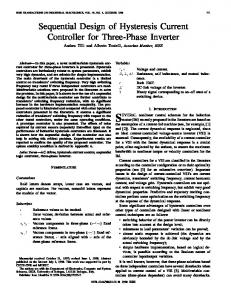
where the feedback gain Kaf is kept constant, but the proper choice of fuzzy switching gain &Kas can accelerate the state trajectories to reach the sliding hyper plane, and thus the dynamic performances will may be improved. The function of each part of the control (21) is already discussed in detail in Section 2. Now, we consider the design procedure of the fuzzy switching gain matrix AKas as a part of the control signal that will drive the state trajectories from any initial state condition to the sliding surface. 4.1. Design of switched gain matrix elements AKas ^ based on fuzzy logic approach We have considered a1xa,iX (see equation (26)) as the linguistic input variable and linguistic variable AKas lk is quantized into six linguistic variables. The universe of discourse for each membership function is selected based on some trails and these are shown in Figure 1. Based on the expressions (25) - (26) (derived in the previous section), we calculate fuzzy logic based switch gain matrix elements AKas lk using the following decision rules. For k = 1,2,..., m: Ri: R2: R3: R4:
If If If If
aixa>fc aiXa,* &ixaik arf^k
is PL then &Kaslk is PL is PM then ~KEaslk is PM. is PZ then A ¥ * s U is PS. is NZ then &K*aslk is NS.
613
Design of Reaching Phase for Variable Structure Controller
R 5 : If (Tixayk is NM then AKaslk
is NM.
R 6 : If vixa,k
is NL.
is NL then AK*aslk
A /
NL
yг\Xa,k)
M— -2Li
NL
-L\,k
NM NS
\ 2Li,k
L\,k
rAA:Lfi*T
PS
PL
CT\ Xa,k
PM PL
л, - 2 L2,k
-2L
**£? \*3?* H\ -cc^H к
2Lгj
AKasAk
к
Fig. 1. Membership functions for each input and output.
Defuzzification. The crisp output AKas i • is obtained by choosing the center-ofarea (centroid) defuzzification method and it is given by AK
as.гj
^(pr„Mti^{^K..n)
(42)
It has been observed that a large switching gain with proper sign of AKaSi tj will drive the state trajectories to the sliding surface rapidly. Transformed switch gain matrix AKa8 y is then changed to original switch gain matrix AKa8 by using the proper matrix inverse HB2 (as discussed in Section 3). Furthermore, when the state trajectories hitting the sliding surface an equivalent control law (35) is then applied to maintain the motion of the states along sliding hyper plane and ensures the trajectory remains on the surface once it gets there. 5. SIMULATION RESULTS To demonstrate the effectiveness of the proposed controllers in presence of parameter perturbation and external disturbances, a load-frequency control problem of two-area
614
G. RAY, S. DEY AND T.K. BHATTACHARYYA
interconnected power system is considered. The nominal system is represented in the state space form by the equation X(t) = AX(t) + BU(t) + Td(ť)
(43a)
Y(t) = CX(t)
(43b)
where X(t) =[ A/i APgl AXgl APtie A/ 2 APg2 AXg2 ] T . A/i and A/2 are the deviation in frequencies, APt{e is the change in tie-line power, APgl and APg2 are the change in turbine-generator outputs, AXgl and AXg2 are the change in outputs of the governors. Furthermore, U=[
APcl
APc2
]T,
di
d=[
d2
f .
Area-control error in Area-1 ACEi = A/i +AP t { e and in Area-2 ACE2 = Af2—APtie are the outputs of the composite system. The following are the nominal system matrices: 1
0 A=
Kp\
TPI
T* 01 2 0 0 J
1 ' 0 0 TGX 0 0 0
BT =
^л_ 0 0 0 0 0
~ŤЪ 0 0
1 Tтi
TTl
1 RITGI
0 0
Kpл
0
0 0
т °
0 0
0 0
0
0
J
KP2 TP2
0
0 0
0
г
TG2
11_ 2 Тp2
ІVP2 TP2
1 Ä2TG2-
г =
1
0 0 0 0
0 0 0 —т*
тP1
0
•
Kp\ TPl
0 0
TТ2
0 0 0 0 0 1 Tт2
0
TG2
0 0 0 0 0
KPЛ
тP1
.
0 0" 0 0
The following nominal parameters are used [5]: = 20.0 s; TT = TT\ = T T 2 = 0.3 s; r a = r a i = T G 2 = 0 . 0 8 s;
TP=TP1=TP2
KP = KP1 = KP2 = 120 Hz / p.u.MW;
R = RX=R2
=2.4 Hz / p.u.MW.
There are always errors present in such models due to linearization, unmodelled dynamics, etc. Moreover, the power system operating conditions change with time leading to changes in system linearized parameters and the following range of system parameter variations are considered: ^r e [ 0.025 0.075 ] , Tp J±-
e [ 2.6041
^ G [ 3.0 9.0 ] , Tp 7.8124 ] ,
^ - G [ 2.333 IT
±- € [ 8.75 16.25 ]
4.333 ]
Design of Reaching Phase for Variable Structure Controller ..
615
The nominal system matrices are as follows:
A=
-0.05 0.0 -5.2083 0.545 0.0 0.0 0.0 Bт =
Гт =
6.0 -3.33 0.0 0.0 0.0 0.0 0.0 ' 0.0 0.0
0.0 3.33 -12.5 0.0 0.0 0.0 0.0 0.0 0.0
12.5 0.0 0.0 0.0
" -6.0 0.0 0.0 0.0
and C =
1.0 0.0
0.0 0.0
-6.0 0.0 0.0 0.0 6.0 0.0 0.0
0.0 0.0 0.0 0.0 0.0 1.0 0.0 -1.0
0.0 0.0 0.0 -0.545 -0.05 0.0 -5.2083
0.0 0.0 0.0 0.0 6.0 -3.33 0.0
0.0 0.0
0.0 12.5
0.0 -6.0
0.0 0.0
0.0 0.0 0.0 0.0 0.0 3.33 -12
0.0 0.0 0.0 0.0
0.0 0.0 1.0 0.0
0.0 " 0.0 •
Note that our nominal system is not in a regular form of equation (18) and (19). One can use a suitable state transformation to get the desired form. In the present example, the states are rearranged to obtain the system description in regular form and it is given by X(t)=[Af1
AP9l
AP92
A/ 2
APtie
AX9l
AX,2]T.
For the present example, we note that the physical interpretation of the states is remaining same after transformation and in general, it is not true. Corresponding transformed nominal system matrices are
=
6.0 -3.33 0.0 0.0 0.0 0.0 0.0
вт =
' 0.0 0.0 0.0 0.0
0.0 0.0
гт =
' -6.0 0.0 0.0 0.0 0.0 0.0 0.0 0.0 0.0 0.0 0.0 -6.0 0.0 0.0 •
A
0.0 0.0 -3.33 0.0 6.0 0.0 0.0
-6.0 0.0 0.0 0.0 6.0 0.0 0.0
0.0 0.0 0.0 -0.545 -0.05 0.0 -5.2083
" -0.05 0.0 0.0 0.545 0.0 -5.2083 _ 0.0
0.0 0.0 12.5 0.0 0.0 0.0
0.0 3.33 0.0 0.0 0.0 -12.5 0.0
0.0 0.0 3.33 0.0 0.0 0.0 -12.5
0.0 12.5
and
č =
' 1.0 0.0 0.0 1.0 0.0 0.0 0.0 -1.0
Define x\ = [ A/i ДP„, дi
Д P 92 ű2
APtie t
0.0 ().0 1.0 ().0
0.0 " 0.0 .
A/2 ] and XT = [ AXgl
AXg2 ].
616
G. RAY, S. DEY AND T.K. BHATTACHARYYA
Case A: It should be pointed out that if the original system parameters are free from perturbation and not excited by external disturbance then it is sufficient to design a P-type sliding surface. When the system state trajectory comes on the sliding surface the closed loop dynamics are described by reduced order model (8). The state feedback control gain Si of the reduced order model (8) (switching function) can be found out by minimizing the performance index
/ (Xf QXX + xlRX2)
Jo
át
(44)
where Q = 15 • J5X5 and R = 10 • I2x2The resulting value of switching surface gain matrix
5=
1.2053 -0.0023
1.6153 -0.0016
-0.0016 1.6153
-0.8141 0.8141
-0.0023 1.2053
1 0
0 1
(45)
The equivalent control law (10) is give by
u
^
4568
= -[o°o,0355
0.1479 -0.0007
-0.0007 0.1479
-0.5797 0.5797
0.0355 -0.4568
-0.5693 -0.0004
-0.0004 -0.5693
]x(t).
(46) The range space eigenvalues are located at 0.4 and 0.3 that are unstable and the corresponding fixed gain matrix is given by
кf =
-0.4954 0.0356
0.0962 -0.0006
-0.0006 0.1091
-0.5536 0.5601
0.0356 -0.4857
-0.6013 -0.0004
-0.0004 -0.5933
To satisfy the reaching conditions (28) based on Householder method the elements of transformed switched gain matrix (AKas) are functions of time and they are shown in Figures 5-6. Computation of Aif a u based on fuzzy logic approach (see Figure 1): Width of input (viXa,k) membership function, 2L\^ = 2 , k = 1,2,, .,ra. Width of output {&Kas lk) membership function, 2L2,fc = 2, k = 1,2,. ,ra. The computer simulation of the composite system has been performed taking a initial state disturbance of X(0) = [ 0.5 0 0 0 0 0 0 ] . Design of switch gain matrix based on fuzzy logic approach (soft computing) is compared with that of hard switching gain matrix and comparison of system responses using the proposed control strategies are shown in Figures 2 - 6 . It is observed that the switched gain components designed based on fuzzy logic approach are much smooth than the hard switched gain components (see Figures 5-6). As a result, the frequency deviation and area-control error responses based on soft switching seem to be better than the hard switching control actions (see Figure 2).
Design of Reaching Phase for Variable Structure Controller
617
...
2
4 Time ( s e c )
Householder Transformation Method Fuzzy Controller
2
4 Time ( s e c )
2
4 Time ( s e c )
F i g . 2 . Comparison of nominal system responses with state disturbance only.
Case B : A PI-type sliding is chosen as in equation (20) when the system response is affected with parameter perturbations and external disturbances. Switching function is then designed by adopting the procedure as discussed in Section 2. Selecting the value of Qa = 15L7x7 and Ra = 10I2x2, the corresponding sliding surface gain matrices are 5 =
1.5874 1.8662 0.0167 -1.0052 0.0266 1 0 0.0266 0.0167 1.8662 1.0052 1.5874 0 1
and
W =
1.2247 0 0 1.2247
618
G. RAY, S. DEY AND T.K. BHATTACHARYYA
AACE2
-0.04І
O
Ü.8
O.б
i.-
•
•
\\
0.4 0.2
o.o -o; O
2 4 Time (Secs)
УI ^ _ _ . . 1 2 3 Time (Sees) With Hard switching structure A k a s
-0.041
2 4 Time (Sees) With soft switching structure A k *
6
Fig. 3. Area control errors and sliding surface trajectories.
1
2 3 Time(sec) With hard switching structure A K a s
2 4 Time(sec) With soft switching structure AK^S
Fig. 4. Comparison of control input structure.
Design of Reaching Phase for Variable Structure Controller ...
1.0
4.0
0
30
-1.0
2.0
Aкll
-2.0
"
ДKjt,
•
1.0
-3.0
0
.
-4.0
1 2 Time(sec)
.
-1.0
0.1 0
1
2 3 Time(sec)
0.1 0
"
-.2 •
A K
2 1
-.2 -0.4
-0.4 -0.6
619
' 1 2 Time(sec)
-0.6
1
2 3 Time(sec)
Fig. 5. Hard switching structures (Householder method)
2
3 4 Time(sec)
•
дк22
AKa3.
2 3 4 Time(sec)
Fig. 6. Soft switching structures (fuzzy logic controller)
AKas.
620
G. RAY, S. DEY AND T . K . BHATTACHARYYA
0.6
Time(sec)
Time(sec) 0.1
-0.05 Time(sec)
Time(sec)
Parameter perturbation (upper bound) Parameter perturbation (lower bound) R a d o m parameter perturbation around nominal system parameters Nominal s y s t e m parameters
Time(sec)
Time(sec)
F i g . 7. System responses for state disturbance and 10 % s t e p change in the load d e m a n d in area 1 (Householder Method).
Design of Reaching Phase for Variable Structure Controller ...
621
The range space eigenvalues are placed at 0.4 and 0.3 and the corresponding fixed gain matrix Kaf of the augmented system is obtained using the expression Sai Aai = KiSai, i = 1,2,..., m (see Section 2, after equation (22)) Kaf-
-0.4195 0.2046 0.0078 -0.6190 0.0429 -0.0392 0 -0.5344 0.0045 0.0431 0.0079 0.2196 .0.6271 -0.5264 -0.4068 0 -0.0294 0.0045
The equivalent control law (C7*q) (see equation (35)) is employed to the system while the states slide along the sliding surface and does not satisfy the matching condition. To satisfy the reaching conditions (28) based on Householder method, the time varying switched gain matrix is designed and subsequently the reaching conditions are satisfied. Simulation results are shown with an initial state disturbance of X(0) = [ 0.5
0
0
0
0
0
0 ]
T
and 10 % step change in load demand in area-1. Performance of the system based on the proposed variable structure control schemes has been studied qualitatively and system responses are shown in Figure 7, which proves the robustness of the designed techniques. An equivalent control law U*q(t) is employed (see equation (35)) while the system trajectory hits the sliding surface to maintain the state trajectory on the sliding surface. The term Ueq in equation (35) is given by Ueą(t) = -
-0.3687 0.0437
0.2644 0.0083
0.0083 0.2644
-0.6512 0.6512
0.0437 -0.5824 0.0845 -0.5770 0.0045 -0.8024
X(t).
6. CONCLUSIONS A new moving sliding surface based on Householder method is considered for ap plication to higher order variable structure systems. The proposed method requires less number of switching gain vector elements as compared to that of White et al. method [8]. The proposed method does not require to satisfying any additional in equality constraints to meet the reaching condition. Design of transformed switch gain matrix elements based on fuzzy logic approach also provides useful result for smooth control action. It is to be noted that the Householder based VSS with slid ing mode controller increases on-line computation burden but works satisfactorily while disturbance-matching condition is not satisfied. The simulation results reveal the system dynamics remain insensitive to the parametric uncertainties and external disturbances only after the system reaches the sliding surface. (Received July 18, 2003.)
REFERENCES [1] C. L. Chen and M. H. Chang: Optimal design of fuzzy sliding mode control: A com parative study. Fuzzy Sets and Systems 93 (1998), 37-48. [2] C. G. Chen, M. H. Lin, and J. M. Hsiao: Sliding mode controllers design for linear discrete-time systems with matching perturbations. Automatica 36 (2000), 1205-1211.
622
G. RAY, S. DEY AND T.K. BHATTACHARYYA
[3] R. A. DeCarlo, S. H. Zak, and G. P. Matthews: Variable structure control of nonlinear multivariate systems: A tutorial. Proc. IEEE 76 (1988), 212-232. [4] C. Edwarda and S.K. Spurgeon: Sliding Mode Control: Theory and Applications. Taylor and Francis, London 1998. [5] C. E. Fosha and O.I. Elgerd: The megawatt-frequency control problem: A new approach via optimal control theory. IEEE Trans. Power Apparatus Systems 89 (1970), 563-577. [6] S. Gutman: Uncertain dynamical systems: a Lyapunov min-max approach. IEEE Trans. Automat. Control 24 (1979), 437-443. [7] J. Y. Hung, W. Gao, and J. C. Hung: Variable structure control: a survey. IEEE Trans. Industrial Electronics 40 (1993), 2-22. [8] N. Nobel and J. W. Daniel: Applied Linear Algebra. Prentice-Hall, Englewood Cliffs, NJ 1988. [9] J. J. E. Slotine and W. Li: Applied Non-Linear Control. Prentice-Hall, Englewood Cliffs, NJ 1991. [10] V.I. Utkin: Variable structure systems with sliding modes. IEEE Trans. Automat. Control 22 (1977), 212-222. [11] B. A. White and P. M. Silson: Reachability in variable structure control systems. Proc. IEE-D (Control Theory and Applications) 131 (1984), 3, 85-91. [12] D. S. Yoo and M. J. Chung: A variable structure control with simple adaptation laws for upper bounds on the norm of the uncertainties. IEEE Trans. Automat. Control 37 (1992), 860-864.
Goshaidas Ray and T. K. Bhattach'aryya, Department of Electrical Engineering, Indian Institute of Technology, Kharagpur-721302. India, e-mails: gray,
[email protected]. ernet.in Sitansu Dey, Tata Consulting Engineering, Block EP and GP Sector-V, Salt-lake, Electronic Complex, Kolkata-700091. India.