3.5 Application Case: Obstacle Detection in Railway Infrastruc- ture Control System . .... are node S1 and S2 voltages, referencing Fig 5.2. . . 89. Figure 5.4 ...... Our first prototype is a standalone MicroBlaze system that implements ...... [55] M. R. Guthaus, J. S. Ringenberg, D. Ernst, T. M. Austin, T. Mudge, and. R. B. Brown.
Th` ese de doctorat Pour obtenir le grade de
Docteur de l’Universit´ e de VALENCIENNES ET DU HAINAUT-CAMBRESIS Discipline: Informatique Pr´ esent´ ee et soutenue par: Ihsen, ALOUANI. Le 26/04/2016, ` a Valenciennes Ecole doctorale : Sciences Pour l’Ing´ enieur (SPI) Equipe de recherche, Laboratoire : Laboratoire d’Automatique, de M´ ecanique et d’Informatique Industrielles et Humaines (LAMIH)
Design of Self-Tuning Reliable Embedded Systems and its Application in Railway Transportation Systems Pr´ esident de jury: • Bertrand Granado. Professeur, Universit´ e Pierre et Marie CURIE Rapporteurs • Walid Najjar. Professor, University of California Riverside • Amer Baghdadi. Professor, Universit´ e TELECOM Bretagne Examinateurs • Carlos Valderrama. Professeur, Universit´ e de Mons, Belgique • Mazen Saghir. Professeur, American University of Beirut Directeurs de th` ese • Niar, Smail. Professeur, UVHC • Rivenq, Atika. Professeur, UVHC Co-encadrant de th` ese • El-Hillali, Yassin. Maitre de Conf´ erences, UVHC
To my beloved parents, To my loving wife, In`es, and to the soul of my Grandma’, Mema... I dedicate this work.
Abstract During the last few decades, a tremendous progress in the performance of semiconductor devices has been accomplished. In this emerging era of high performance applications, machines need not only to be efficient but also need to be dependable at circuit and system levels. Several works have been proposed to increase embedded systems efficiency by reducing the gap between software flexibility and hardware high-performance. Due to their reconfigurable aspect, Field Programmable Gate Arrays (FPGAs) represented a relevant step towards bridging this performance/flexibility gap. Nevertheless, Dynamic Reconfiguration (DR) has been continuously suffering from a bottleneck corresponding to a long reconfiguration time. In this thesis, we propose a novel medium-grained high-speed dynamic reconfiguration technique for DSP48E1-based circuits. The idea is to take advantage of the DSP48E1 slices runtime reprogrammability coupled with a re-routable interconnection block to change the overall circuit functionality in one clock cycle. In addition to the embedded systems efficiency, this thesis deals with the reliability chanllenges in new sub-micron electronic systems. In fact, as new technologies rely on reduced transistor size and lower supply voltages to improve performance, electronic circuits are becoming remarkably sensitive and increasingly susceptible to transient errors. The system-level impact of these errors can be far-reaching and Single Event Transients (SETs) have become a serious threat to embedded systems reliability, especially for especially for safety critical applications such as transportation systems. The reliability enhancement techniques that are based on overestimated soft error rates (SERs) can lead to unnecessary resource overheads as well as high power consumption. Considering error masking phenomena is a fundamental element for an accurate estimation of SERs. This thesis proposes a new cross-layer model of circuits vulnerability based on a combined modeling of Transistor Level (TLM) and System Level Masking (SLM) mechanisms. We then use this model to build a self adaptive fault tolerant architecture that evaluates the circuit’s effective vulnerability at runtime. Accordingly, the reliability enhancement strategy is adapted to protect only vulnerable parts of the system leading to a reliable circuit with optimized overheads. Experimentations performed on a radar-based obstacle detection system for railway transportation show that the proposed approach allows relevant reliability/resource utilization tradeoffs. Keywords: Embedded Systems - Reliability - Dependability - Dynamically Reconfigurable Architectures - Soft Errors
R´ esum´ e Un ´enorme progr`es dans les performance des semiconducteurs a ´et´e accompli ces derni`eres ann`ees. Avec l’´emergence d’applications complexes, les syst`emes embarqu´es doivent ˆetre `a la fois performants et fiables. Une multitude de travaux ont ´et´e propos´es pour am´eliorer l’efficacit´e des syst`emes embarqu´es en r´eduisant le d´ecalage entre la flexibilit´e des solutions logicielles et la haute performance des solutions mat´erielles. En vertu de leur nature reconfigurable, les FPGAs (Field Programmable Gate Arrays) repr´esentent un pas consid´erable pour r´eduire ce d´ecalage performance/flexibilit´e. Cependant, la reconfiguration dynamique a toujours souffert d’une limitation li´ee a` la latence de reconfiguration. Dans cette th`ese, une nouvelle technique de reconfiguration dynamique au niveau ”grain-moyen” pour les circuits a` base de blocks DSP48E1 est propos´ee. L’id´ee est de profiter de la reprogrammabilit´e des blocks DSP48E1 coupl´ee avec un circuit d’interconnection reconfigurable afin de changer la fonction impl´ement´ee par le circuit en un cycle horloge. D’autre part, comme les nouvelles technologies s’appuient sur la r´eduction des dimensions des transistors ainsi que les tensions d’alimentation, les circuits ´electroniques sont devenus de plus en plus susceptibles aux fautes transitoires. L’impact de ces erreurs au niveau syst`eme peut ˆetre catastrophique et les SETs (Single Event Transients) sont devenus une menace tangible `a la fiabilit´e des syst`emes embarqu´es, en l’occurrence pour les applications critiques comme les syst`emes de transport. Les techniques de fiabilit´e qui se basent sur des taux d’erreurs (SERs) surestim´es peuvent conduire a` un gaspillage de ressources et par cons´equent un cout en consommation de puissance ´electrique. Il est primordial de prendre en compte le ph´enom`ene de masquage d’erreur pour une estimation pr´ecise des SERs. Cette th`ese propose une nouvelle mod´elisation inter-couches de la vuln´erabilit´e des circuits qui combine les m´ecanismes de masquage au niveau transistor (TLM) et le masquage au niveau Syst`eme (SLM). Ce mod`ele est ensuite utilis´e afin de construire une architecture adaptative tol´erante aux fautes qui ´evalue la vuln´erabilit´e effective du circuit en runtime. La strat´egie d’am´elioration de fiabilit´e est adapt´ee pour ne prot´eger que les parties vulnerables du syst`eme, ce qui engendre un circuit fiable avec un cout optimis´e. Les experimentations effectu´ees sur un syst`eme de d´etection d’obstacles `a base de radar pour le transport ferroviaire montre que l’approche propos´ee permet d’´etablir un compromis fiabilit´e/ressources utilis´ees. Mots cl´ es : Syst`emes Embarqu´es- Fiabilit´e - Architectures Reconfigurables Dynamiquement- Erreurs Transitoires
Contents Contents
i
List of Figures
iv
List of Tables
vii
References
viii
1 Introduction 1.1 General Context . . . . . . . . . . . . . . . . . . . . . . 1.2 Motivations . . . . . . . . . . . . . . . . . . . . . . . . 1.2.1 Overcoming FPGAs Reconfiguration Latency . 1.2.2 Reliability challenge in new sub-micron systems 1.3 Contributions and thesis outline . . . . . . . . . . . . .
. . . . .
. . . . .
. . . . .
2 Accelerating Dynamic Reconfiguration in DSP-based Circuits 2.1 Introduction . . . . . . . . . . . . . . . . . . . . . . . . . . . 2.2 Related works . . . . . . . . . . . . . . . . . . . . . . . . . . 2.3 Proposed approach . . . . . . . . . . . . . . . . . . . . . . . 2.4 ARABICA: A Reconfigurable Arithmetic Block for ISA CustomizAtion . . . . . . . . . . . . . . . . . . . . . . . . . . . 2.4.1 Architecture . . . . . . . . . . . . . . . . . . . . . . . 2.4.2 Test Platform . . . . . . . . . . . . . . . . . . . . . . 2.4.3 Experimental Methodology . . . . . . . . . . . . . . . 2.4.4 Results . . . . . . . . . . . . . . . . . . . . . . . . . . 2.5 A DSP-based Reconfigurable Unit for Signal Processing Applications . . . . . . . . . . . . . . . . . . . . . . . . . . . . 2.5.1 Circuit Architecture . . . . . . . . . . . . . . . . . . 2.6 Resource utilization and Power Consumption . . . . . . . . . 2.7 Conclusions . . . . . . . . . . . . . . . . . . . . . . . . . . .
i
. . . . .
1 1 2 4 5 6
9 . 9 . 14 . 15 . . . . .
19 20 22 24 25
. . . .
30 30 34 34
CONTENTS
ii
3 Self Adaptive Redundancy for Reliable Obstacle Detection Systems 3.1 Introduction . . . . . . . . . . . . . . . . . . . . . . . . . . . 3.2 Background and Related Works . . . . . . . . . . . . . . . . 3.2.1 Soft Errors in Combinational Circuits . . . . . . . . . 3.2.2 Reliability Enhancement Techniques . . . . . . . . . 3.3 Input-dependent Masking Mechanisms . . . . . . . . . . . . 3.3.1 TLM: Transistor-Level Masking Mechanism . . . . . 3.3.2 SLM: System-Level Masking Mechanism . . . . . . . 3.4 ARDAS: Adjustable Redundancy in DSP-based Architectures for Soft errors resiliency . . . . . . . . . . . . . . . . . . . . 3.4.1 Vulnerability Modeling . . . . . . . . . . . . . . . . . 3.4.2 Proposed Approach . . . . . . . . . . . . . . . . . . . 3.5 Application Case: Obstacle Detection in Railway Infrastructure Control System . . . . . . . . . . . . . . . . . . . . . . 3.5.1 Reliability Enhancement . . . . . . . . . . . . . . . . 3.5.2 Power, area and performance overheads . . . . . . . . 3.6 Conclusion and future works . . . . . . . . . . . . . . . . . . 4 Register File Reliability Enhancement Through Adjacent Narrow-width Exploitation 4.1 Introduction . . . . . . . . . . . . . . . . . . . . . . . . . . . 4.2 Related Work . . . . . . . . . . . . . . . . . . . . . . . . . . 4.3 Proposed Architecture: Adjacent Register Hardening (ARH) 4.3.1 Circuit Level Reliability Enhancement . . . . . . . . 4.3.2 Architecture Level Organization . . . . . . . . . . . . 4.4 Experiments . . . . . . . . . . . . . . . . . . . . . . . . . . . 4.5 Conclusion and future work . . . . . . . . . . . . . . . . . . 5 SRAM Memories Reliability Enhancement 5.1 Introduction . . . . . . . . . . . . . . . . . . . . . 5.2 AS8-SRAM: Asymmetric SRAM Architecture For Hardening Enhancement . . . . . . . . . . . . . . 5.2.1 Background and Related Work . . . . . . 5.3 AS8-SRAM: Architecture . . . . . . . . . . . . . . 5.3.1 Experimental methodology . . . . . . . . . 5.3.2 Results . . . . . . . . . . . . . . . . . . . . 5.3.3 Reliability under nominal Vdd . . . . . . . 5.3.4 Reliability under voltage scaling . . . . . . 5.3.5 System level energy consumption . . . . . 5.4 Conclusion . . . . . . . . . . . . . . . . . . . . . .
. . . . . . Soft Error . . . . . . . . . . . . . . . . . . . . . . . . . . . . . . . . . . . . . . . . . . . . . . . . . . . . . .
. . . . . . .
35 35 39 39 40 41 41 49
. 51 . 51 . 54 . . . .
58 60 62 64
. . . . . . .
65 65 67 69 70 72 77 81
82 . 82 . . . . . . . . .
84 84 85 87 90 90 91 93 94
CONTENTS 6 Conclusion 6.1 Contributions . . . . . . . . . . . . . . . . . . . . . . . . . . 6.1.1 A High Speed Reconfiguration Technique for DSPbased Circuits . . . . . . . . . . . . . . . . . . . . . . 6.1.2 An Auto-tuning Fault Tolerance Architecture for Obstacle Detection in Railway Transportation . . . . . . 6.1.3 Memories Reliability Enhancement . . . . . . . . . . 6.2 Future Work . . . . . . . . . . . . . . . . . . . . . . . . . . . Bibliography
iii 96 . 97 . 97 . 97 . 98 . 98 103
List of Figures Figure 1.1 Figure 1.2 Figure 1.3 Figure 1.4 Figure 2.1 Figure 2.2 Figure 2.3 Figure 2.4 Figure Figure Figure Figure Figure
2.5 2.6 2.7 2.8 2.9
Figure 2.10 Figure 2.11 Figure 2.12 Figure Figure Figure Figure Figure
2.13 2.14 2.15 2.16 2.17
Research Program Working Packages . . . . . . . . The trend of CMOS technologies use in the automotive domain vs CMOS technologies evolution [16] . An overview on the thesis contributions . . . . . . . Different computing architectures comparison in terms of Flexibility and Performance . . . . . . . . .
.
1
. .
3 3
.
4
Conventional FPGA fabric architecture [26] . . . . . . Minimum and maximum Number of DSP48 Slices per Virtex Family . . . . . . . . . . . . . . . . . . . . . . Xilinx DSP48E1 block internal architecture [14] . . . Typical coarse-grained reconfigurable computing platform [30] . . . . . . . . . . . . . . . . . . . . . . . . . ARENA circuits general architecture . . . . . . . . . . Example of RC generation . . . . . . . . . . . . . . . IEEE 754 single precision format . . . . . . . . . . . ARABICA internal architecture . . . . . . . . . . . . The test platform including ARABICA, a MicroBlaze processor and input/output buffers . . . . . . . . . . FPGA Resource Utilization . . . . . . . . . . . . . Execution Performance . . . . . . . . . . . . . . . . . Normalized Static, Dynamic, and Total Power Consumption . . . . . . . . . . . . . . . . . . . . . . . . . Energy Consumption . . . . . . . . . . . . . . . . . . Input/Output blocks latency overhead . . . . . . . . Optimized Filtering Block for 2D Median filter [83] . . Resource Utilization Compared to Dedicated Circuits Static and Dynamic Power Consumption Compared to Dedicated Circuits . . . . . . . . . . . . . . . . . .
11
iv
13 13 15 18 19 21 22 23 26 26 27 28 29 31 31 32
LIST OF FIGURES
v
Figure 2.18
Architecture of the reconfigurable DSP-based architecture implementing FFT, FIR, Convolution, Median and Mean Filters . . . . . . . . . . . . . . . . . . 33
Figure 3.1 Figure 3.2
Three soft error masking mechanisms . . . . . . . . . TLM Example: Radiation strike hitting PMOS transistor Q3 in a Nand 2 gate within a C17 circuit. The error is masked when the inputs are at ”00” . . . . . TLM and Logical Masking (LM) probabilities for the C17 benchmark . . . . . . . . . . . . . . . . . . . . . Different masking probabilities of a full adder. The 3 input-bits correspond respectively to Cin ,Y and X. . . Architecture of a 4 × 4 multiplier . . . . . . . . . . . Masking probabilities of a 4 × 4 multiplier. S0 to S7 correspond to the outputs. . . . . . . . . . . . . . . . General Architecture of a Threshold-based System . . Simulation flowchart . . . . . . . . . . . . . . . . . . . Design Time Cross-layer Exploration Steps . . . . . . An illustrative circuit of the flexible redundancy used in ARDAS . . . . . . . . . . . . . . . . . . . . . . . . Redundant DSPs and Global Vulnerability in terms of Vulnerability Threshold . . . . . . . . . . . . . . . A general architecture of an obstacle detection system Different raw signals for three frequently faced obstacles Normalized SER for the three correlation circuits: Original, with ARDAS and with TMR. Used DSP resources in terms of V0 is also given. . . . . . . . . . . Overall Correlation circuit with ARDAS architecture . Execution time comparison of the different architectures for two different frequency configurations . . . .
Figure 3.3 Figure 3.4 Figure 3.5 Figure 3.6 Figure Figure Figure Figure
3.7 3.8 3.9 3.10
Figure 3.11 Figure 3.12 Figure 3.13 Figure 3.14
Figure 3.15 Figure 3.16 Figure 4.1 Figure 4.2 Figure 4.3 Figure 4.4
The percentage of appearance in the 32-bit RF of the different effective lengths (in byte). . . . . . . . . . Left: 7T/14T memory cell with nMOS joiners [46] right: JSRAM cell with nMOS joiners[17]. . . . . . Some possible combinations for byte mapping. . . . Top: Three bytes of ”ZYXW” number in reg-i are replicated in sign bits of reg-i+1. ”V” number in regi+1 is not replicated. Bottom: easy routing by byte reordering. . . . . . . . . . . . . . . . . . . . . . . .
39
43 47 48 49 49 50 52 54 55 57 59 59
60 61 62
. 69 . 71 . 73
. 74
LIST OF FIGURES
vi
Figure 4.5 Figure Figure Figure Figure Figure
Left: Write Access Circuit, Wordline and Joiner Signals Right: Read Access Multiplexer . . . . . . . . . . 4.6 Simplified datapath for RF write access including EL detection . . . . . . . . . . . . . . . . . . . . . . . . . 4.7 Fault injection flowchart. . . . . . . . . . . . . . . . . 4.8 Simulation setup using the WATTCH power simulator 4.9 Normalized error rate of ARH RF vs conventional RF. 4.10 Normalized power consumption of ARH RF vs conventional RF. . . . . . . . . . . . . . . . . . . . . . .
Figure 5.1 Figure 5.2 Figure 5.3 Figure 5.4 Figure 5.5 Figure 5.6 Figure 5.7
Figure 5.8
Standard 6T-SRAM cell circuit . . . . . . . . . . . AS8-SRAM Architecture . . . . . . . . . . . . . . . Graphical definition of critical charge. VS1 and VS2 are node S1 and S2 voltages, referencing Fig 5.2. . Critical charge and corresponding SER by cell for the different tested circuits under nominal Vdd . . . . . Critical charge versus supply voltage scaling . . . . Access power by cell for different Qc values . . . . . Probability of failure (POF) vs Vdd for a 16kB cache using: SECDED cache, CC and AS8-SRAM-based cache under iso-area constraint . . . . . . . . . . . Energy and performance results for a set of embedded benchmarks . . . . . . . . . . . . . . . . . . . . . .
75 76 79 79 80 80
. 83 . 86 . 89 . 90 . 91 . 92
. 92 . 95
List of Tables Tableau 2.1 ARABICA instruction clock cycle latencies . . . . . . 22 Tableau 2.2 ARABICA instruction benchmarks . . . . . . . . . . 25 Tableau 2.3 Test-platform Resource Overhead . . . . . . . . . . . 29 Tableau 3.1 Probabilities of TLM of a NAND, XOR and AND logic gates for the different input combinations . . . . 44 Tableau 3.2 The correlation circuit characteristics . . . . . . . . . 57 Tableau 3.3 Resource utilization, power and maximum frequency for the original circuit, TMR and ARDAS. . . . . . . 63 Tableau 4.1 The number of instructions for the used benchmarks . 78 Tableau 5.1 Sizes of the transistors used in the different tested memory cells. . . . . . . . . . . . . . . . . . . . . . . 88
vii
List of Algorithms Algorithm 1 Algorithm for Dynamically Reconfigurable Circuit (DRC) generation17 Algorithm 2 Compute probability of error masking for an input combination Ic 46
viii
Chapter 1
Introduction
1.1
General Context
This thesis is funded by the IRT (Technological Research Institute) Railenium [3]. IRT is a foundation for scientific cooperation whose role is to perform a research, development and innovation strategy that targets railway infrastructure and systems, setting up R&D projects and carrying out research activities, applications and training sessions.
WP1
Process and Materials
WP8
WP2
Economy & Sustainable development
WP7
Civil Engineering
R&D
Modeling & Virtual Prototyping
WP6
WP3
Energy Management
WP4
Op-misa-on & Asset Management
Telecommunica-on & Intelligent Systems
WP5
Sensors & Diagnos-c
Figure 1.1: Research Program Working Packages As shown in Figure 1.1, IRT research activities are composed of 8 Working Packages (WPs) and our work is a part of the WP4. Within WP4, this 1
CHAPTER 1. INTRODUCTION
2
research is conducted in the framework of the SURCIFER project. This latter’s goals are: to create tools and methods that enhance rail operation and management and develop innovative control-command and signaling systems. The project thereby tries to enhance systems reliability and safety while optimizing cost and utilized resources. The program takes into account telecommunication systems robustness, reliability, as well as to design effective positioning systems.
1.2
Motivations
The huge amount of data and complexity of the tasks supported by embedded systems imposed an inevitable focus on circuits flexibility to allow resources reuse. For example, safety-oriented embedded systems in railway transportation domain handle data that is continuously forwarded from several heterogeneous sensors. These applications require various interconnected tasks including signal processing, communication, obstacle detection and recognition ...etc. Moreover, embedded systems are increasingly utilized in emerging fields such as Intelligent Transportation Systems (ITS) and the gap between the technology trend and the practically implemented technology is getting narrower. In fact the delay of about 5 years that used to be a sufficient technological ”comfort zone” to integrate mature and stable technologies is disappearing. As shown in Figure 1.2, by the year 2015, the gap between CMOS technology trends and the utilized technology is vanishing because of the new applications high requirements. Moreover, the integration of new technologies to build these systems results in an increasing sensitivity to external-event-induced errors. In fact, the International Technology Roadmap for Semiconductors (ITRS) predicts that every new generation of integrated circuits reduces the lifetime of the corresponding systems by half [7]. This thesis focuses on the flexibility of FPGA-based circuits as well as on the reliability challenge in embedded systems new generations. The motivations illustrated by Figure 1.3 are to design a very fast reconfiguration process and to propose low overhead reliability enhancement techniques in new computing systems.
CHAPTER 1. INTRODUCTION
3
Figure 1.2: The trend of CMOS technologies use in the automotive domain vs CMOS technologies evolution [16]
Figure 1.3: An overview on the thesis contributions
CHAPTER 1. INTRODUCTION
1.2.1
4
Overcoming FPGAs Reconfiguration Latency
As shown in Figure 1.4, the different computing architectures vary, mainly, depending on their specifications in terms of flexibility and performance. The major benefit from ASICs is their high performance, while microprocessors offer a comfortable flexibility to the programmers. Reconfigurable architectures offer a trade-off between the two computing architectures. Field Programmable Gate Arrays (FPGA) is a commonly utilized reconfigurable architecture in a wide range of application fields. This is mainly due to their flexibility, low cost and relatively short time-to-market. FPGAbased designs implement circuits with continuously increasing requirements and complexity. Accordingly, FPGAs are solicited to host larger designs while boards size growth is limited by the scale of the silicon process technology. Hence, to cope with high applications requirements and hardware resources budget, engineering designs saw the appearance of the Dynamic Reconfiguration (DR) approach. DR’s primary contribution is the flexibility increase by reusing hardware resources.
Figure 1.4: Different computing architectures comparison in terms of Flexibility and Performance The reconfigurable aspect of FPGAs is, by consequence, a key feature that allows building efficient and flexible embedded systems. Nevertheless,
CHAPTER 1. INTRODUCTION
5
DR has been continuously suffering from the shortcoming of a long configuration latency. This is mainly due to the technological constraints related to the bitstream downloading technique in the conventional fine-grained FPGA reconfiguration process. To overcome this shortness, a multitude of the proposed Coarse-Grain Reconfigurable Architectures (CGRAs) and overlay architectures were developed regardless the available FPGA boards different resources. The main limitation of these designs is their complex design flow and the lack of CAD tools that facilitate their utilization. Along with FPGA generations, available resources progress and new hardware elements appear. DSP slices are embedded hardware blocks found in modern FPGAs. These primitives are getting increasing attention and are available with higher numbers in the new boards as they provide area, performance, and power advantages over the equivalent functions implemented using the FPGA fabric. Moreover, DSP slices afford a widely exploitable range of flexibility and can be easily reconfigured at run-time using dedicated signals.Using DSP blocks as Processing Elements (PEs) in overlay architectures leads to better performance with further reconfiguration facilities. This thesis explores techniques towards bridging the performance-flexibility gap through the exploitation of the DSPs’ intrinsic specifications.
1.2.2
Reliability challenge in new sub-micron systems
The progress in nanoscale technologies led to a tremendous development in embedded systems performance. This progress was necessary to cope with new generations of complex and highly requiring applications that go from smart phones multidisciplinary tasks to high security demanding transportation and aerospace applications. Particularly, the railway environment is extremely aggressive because of high electromagnetic fields and low power electronic systems operate close to components with very high voltages and currents from trains. The applications high requirements in terms of performance imply an inevitable increase in systems operating frequencies. This means an increment in dynamic power consumption and additional reliability-related issues because of the timing-violation risks. The designed circuits need to meet
CHAPTER 1. INTRODUCTION
6
reliability and safety standards such as EN 50126, EN 50128 and EN 50129 in railway-dedicated systems. However, as limiting power consumption is primordial for embedded systems designers, new techniques relying on downscaling supply voltage emerged. Furthermore, as new CMOS technologies rely on shrinking transistors size, circuits sensitivity issues became an critical concern. In conclusion, shrunk-transistors-based circuits are operating under aggressively scaled supply voltage. Hence, the susceptibility of these circuits to errors considerably increased and some phenomena that are beforehand considered as very rare became a serious threat to reliability not only for aggressive environments related systems, but also for mainstream applications. Consequently, the increasing sub-micron circuits sensitivity imposed reliability as a priority in electronic systems design process. However, reliability enhancement has a considerable cost: most of the existing error mitigation techniques suffer from huge area and power overheads, or lead to considerable performance penalties. In fact, the reliability enhancement techniques that are based on overestimated Soft Error Rates (SERs) lead to unnecessary resource overheads as well as high power consumption. Nevertheless, within the same application, some data are more critical than others. Accordingly, within the same system, as some errors may be masked, some parts are more vulnerable to errors than others. Hence, considering error masking phenomena is a fundamental element for an accurate estimation of SERs. In this thesis, we propose a new cross-layer model of circuits vulnerability based on a combined modeling of Transistor Level (TLM) and System Level Masking (SLM) mechanisms. We then use this model to build a self adaptive fault tolerant architecture that evaluates the circuit’s effective vulnerability at run-time. Accordingly, the reliability enhancement strategy is adapted to protect only vulnerable parts of the system leading to a reliable circuit with optimized overheads.
1.3
Contributions and thesis outline
The main contributions of this thesis can be formulated as follows: • The proposition of a high speed Dynamic Reconfiguration (DR) tech-
CHAPTER 1. INTRODUCTION
7
nique for DSP-based circuits that overcomes the limitations of the conventional FPGAs DR process: we take advantage from DSP slices flexibility to build circuits having the ability to change the implemented functionality in only one clock cycle, and this, regardless the circuit size and complexity. In order to facilitate the design flow of DR of DSP-based circuits, a tool is proposed. The tool accelerates the design process by generating configuration vectors corresponding to the desired functionality. • A cross-layer modeling of input-dependent masking mechanisms within computing elements: it combines transistor level error masking in combinational circuits and system level masking intrinsic to applications. The model estimates the system vulnerability depending on the signals applied to the inputs. Hence, circuits intrinsic masking phenomena impact on SERs can be estimated at design-time depending on the applied input combination. • A self tuning fault tolerance technique that adapts the reliability strategy to the actual circuit vulnerability obtained from the masking model: depending on the previously cited model, and using the dynamic reconfiguration technique referred to in the first contribution, the system chooses at run-time the redundancy map depending on the vulnerability estimation. As the reliability requirements vary depending on the application field as well as the system operating environment, the proposed technique allows designers to tune the reliability enhancement strategy depending on the actual application, field and operating environment requirements. Hence, it offers more accurately relaxed reliability thereby saving resources as well as power. • A circuit level modified SRAM architecture that hardens the memories against soft errors: with a single inverter put in parallel with the 6TSRAM memory cell, AS8-SRAM increases the critical charge of the cell thereby reducing the probability of soft errors. The advantage of AS8SRAM is its low overhead with comparable hardening results to state of the art techniques.
CHAPTER 1. INTRODUCTION
8
• An architecture level method for register files reliability enhancement in microprocessors: depending on the registers length, we use adjacent registers narrow-width to enhance registers immunity to transient errors. Using this opportunistic fault tolerance technique, the overall processor reliability is enhanced with low additional circuitry and without any additional memory. The remainder of this dissertation is organized as follows. Chapter 2 presents the proposed dynamic reconfiguration technique (ARENA) with two illustration cases: an arithmetic and logic coprocessor that can support a very wide range of operations and a reconfigurable unit that implements a number of signal processing kernels. Chapter 3 builds a cross-layer model for estimating the vulnerability of combinational logic, and presents a self tuned systems for adaptive reliability enhancement. Chapter 4 focuses on SRAM memories immunity to soft errors and presents AS8-SRAM architecture. An architecture level technique to enhance register files reliability is detailed in Chapter 5. The thesis is finally concluded in Chapter 6 and some interesting future ideas to work on in the future are proposed.
Chapter 2
Accelerating Dynamic Reconfiguration in DSP-based Circuits
This chapter proposes a high-speed reconfiguration method for DSP-based circuits.
2.1
Introduction
During the last years, several works have been proposed to reduce the gap between software flexibility and hardware high-performance within embedded systems. Due to their reconfigurable nature, Field Programmable Gate Arrays (FPGAs) represented a relevant step towards bridging this performance/flexibility gap. Nevertheless, Dynamic Reconfiguration (DR) has been continuously suffering from a bottleneck corresponding to a long reconfiguration time. This is mainly due to the technological constraints related to bitstream downloading within the FPGAs conventional reconfiguration process. In this paper, we propose a novel medium-grained high-speed dynamic reconfiguration technique for DSP48E1-based circuits. The idea is to take advantage of the DSP48E1 slices run-time reprogrammability coupled with a re-routable interconnection block to change the overall circuit functionality in one clock cycle. We validate the proposed approach on two commonly used circuits in embedded systems: a fully pipelined arithmetic and logic coprocessor and a Signal Processing (SP) reconfigurable unit. The first design utilizes the same resources to implement a set of single precision, double precision, integer and logic operations while the second fits several widely used 9
CHAPTER 2.
ACCELERATING RECONFIGURATION OF DSP-BASED CIRCUITS
10
DSP-dedicated kernels within the same device. Mobile computing is increasingly demanding powerful application processors that can deliver high levels of performance and energy efficiency in a wide range of application domains. These processors are used to run a mix of applications having varying degrees of computational needs. To provide the necessary level of performance, application processors are increasingly designed around heterogeneous multi-core architectures. To match the widest range of applications, they use dedicated processing units for different functionalities. For example, each of the four ARMv7 processor cores of the Krait 300 CPU include hardware support for SIMD, vector floatingpoint, security, and Java byte code instructions [2]. Such high integration levels increase performance and energy efficiency when applications are well matched to available cores and hardware. However, it can also complicate designs and waste resources when hardware units are under-utilized. Moreover, even when low-power design techniques are used, static power dissipated from poorly utilized resources can reduce energy efficiency. We believe heterogeneity in application processors can be more efficiently supported using reconfigurable hardware architectures that leverage programmable interconnection networks and simple arithmetic and logic units to dynamically organize into specific computational structures. Practically, two well known traditional computing systems are commonly used to execute beforehand implemented tasks. The first way is to rely on dedicated circuits known as Application Specific Integrated Circuit (ASIC) to support the desired functionality in hardware. The second is to run a set of instructions on a processor. As ASICs are designed to a specific task, they are highly efficient. However, once manufactured, the circuit is unchangeable and cannot be reconfigured. Microprocessors, on the other hand, are very flexible and the system functionality is altered just by changing the instructions at software level with absolutely no change on the target hardware. Nevertheless, this flexibility is based on a complex execution process which results in a considerable performance degradation. Hence, designers face a dilemma in choosing the target platform between flexibility and performance at the expense of each other. During the last years, many research works proposed techniques and ar-
CHAPTER 2.
ACCELERATING RECONFIGURATION OF DSP-BASED CIRCUITS
I/O Pads
Configurable Logic Blocks (CLBs)
11
Connection Blocks Switch Blocks Channel Width
Inputs 4x1 LUTs 1 Outputs
2
... 10 CLB
2.1: Island-style FPGA architecture Figure 2.1: Figure Conventional FPGA fabric architecture [26] of overlay architecture, as it allows a user design in the form of a program
chitectures intending to achieve higher performance than microprocessors to be run on the FPGA. There are many soft processor designs for FPGAs without drastic loss in terms of flexibility. In this context, reconfigurable that run the gamut from RISC processors (e.g. Nios II or MicroBlaze), to computing seemed to be a good trade-off that is practically realized through multiprocessor systems [18], to vector processors [6][26]. There has also been FPGAs. The reconfigurable aspect of FPGAs is a relevant step towards work done on mapping coarse grain reconfigurable arrays (CGRAs) to FPGA bridging this performance/flexibility gap within embedded systems. The systems. CGRAs are similar to FPGAs, but with a larger resource such as conventional FPGA fabric architecture is shown in Figure 2.1. Based on an ALU as its basic element, which usually is scheduled between various Configurable Logic Blocs (CLBs) and routable interconnections, FPGAs ofcomputations at di↵erent time slices. The QUKU CGRA overlay [20] is an fer potentially higher performance than soft cores with interesting improveexample of a system designed to run on top of an FPGA, which runs user ment in hardware flexibility. Besides, via Dynamic Reconfiguration (DR), utilizing many coarse grain logic elements in parallel. There designers applications are able to map more functions to the same logic resources which has also been previous work on using FPGAs to implement custom FPGA helps to increase systems productivity and scalability. architectures. The virtual FPGA (vFPGA) [17] is an FPGA overlay archiUnfortunately, conventional FPGA architectures suffer from high cost of tecture that isand meant to work with (JIT) compilation of FPGA power consumption limitation ofjust-in-time speed due to the routing area overhead designs for acceleration of sequences extracted from the dataflow graphs of process. and timing penalty of their bit-level bitstream-based reconfiguration To overcome the shortness caused by mainstream FPGAs’ fine granularity 11 reconfiguration, a multitude of the proposed Coarse-Grain Reconfigurable Architectures (CGRAs) and overlay architectures were developed with little consideration for the available FPGA boards different resources. The main limitation of these designs is their complex design flow and the lack of CAD tools that facilitate their application. Embedded hard primitives, such as DSP48E1 blocks in Xilinx FPGAs shown in Figure 2.3 provide
CHAPTER 2.
ACCELERATING RECONFIGURATION OF DSP-BASED CIRCUITS
12
performance, area and power advantages over the equivalent circuits implemented within FPGA fabric resources. Using these slices as Processing Elements (PEs) in overlay architectures leads to better performance with further reconfiguration facilities. DSP blocks in modern FPGAs are getting increasing focus as they provide a vast range of arithmetic and logic functions, offering high performance and saving Configurable Logic Blocks (CLBs). As these blocks provide areaefficient implementations for multiplication, addition, multiply-accumulate and logical operations, they have been widely used in signal processing applications. Xilinx FPGAs contain flexible DSP48E1 primitives whose behavior can be dynamically programmable. The specific function of these DSP slices can be modified at runtime through special control signals [1]. Figure 2.3 shows the DSP48E1 architecture: Ports A, B, C and D, supply input operands to the multiplier and add/sub/logic block. The specific function carried by a DSP48E1 is controlled by dedicated control signals that enable the DSP to run in different modes. For example, the implemented operation can be configured by ALUMODE, the ALU input selection is specified through OPMODE, and INMODE monitors the pre-adder and input pipeline. Figure 2.2 presents the minimum and maximum number of DSP48 blocks within every Xilinx Virtex family (from Virtex 4 to Virtex 7). The increasing availability of DSP48 slices in Xilinx FPGA families reflects an expanding demand on its utilization by designers. The main contributions of this chapter are the following: • A generic DSP-based reconfiguration approach that achieves high speed reconfiguration based on intrinsic DSP48E1 flexibility enhanced with a reconfigurable interconnection block. • A mapping tool that takes a high level description of the different computational kernels and generates the reconfigurable circuit with the different configuration vectors. This tool bypasses the conventional FPGA compilation flow and maps to the overlay.
CHAPTER 2.
ACCELERATING RECONFIGURATION OF DSP-BASED CIRCUITS
13
Minimum and maximum Number of DSP48 Slices per Virtex Family Min
Max
4032 3032 2032 1032 32 Virtex 4
Virtex 5
Virtex 6
Virtex 7
Figure 2.2: Minimum and maximum Number of DSP48 Slices per Virtex Family
Chapter 2: DSP48E1 Description and Specifics
X-Ref Target - Figure 2-1
CARRYCASCOUT* BCOUT*
ACOUT* 18
48 30
18
A
D
25
30
30
MULT 25 X 18
C
48
INMODE
0
48
X P
M 0 1
25
Dual A, D, and Pre-adder
4
P
4 18
Dual B Register B 30
PCOUT*
ALUMODE
18
B
A
MULTSIGNOUT*
A:B
Y
P
0
C
P
17-Bit Shift
1
48
P PATTERNDETECT PATTERNBDETECT
Z 17-Bit Shift
5
4
CARRYOUT
CREG/C Bypass/Mask
3
MULTSIGNIN*
CARRYIN OPMODE
7
CARRYINSEL
CARRYCASCIN* 48
BCIN*
ACIN*
PCIN*
*These signals are dedicated routing paths internal to the DSP48E1 column. They are not accessible via fabric routing resources. UG369_c1_01_052109
2-1: 7 Seriesblock FPGA DSP48E1 Slice Figure 2.3: Xilinx Figure DSP48E1 internal architecture [14]
DSP48E1 Slice Features This section describes the 7 series FPGA DSP48E1 slice features. The DSP slice consists of a multiplier followed by an accumulator. At least three pipeline registers are required for both multiply and multiply-accumulate operations to run at full speed. The multiply operation in the first stage generates two partial products that need to be added together in the second stage. When only one or two registers exist in the multiplier design, the M register should always be used to save power and improve performance. Add/Sub and Logic Unit operations require at least two pipeline registers (input, output) to run at full speed. The cascade capabilities of the DSP slice are extremely efficient at implementing highspeed pipelined filters built on the adder cascades instead of adder trees. Multiplexers are controlled with dynamic control signals, such as OPMODE, ALUMODE, and CARRYINSEL, enabling a great deal of flexibility. Designs using registers and dynamic opmodes are better equipped to take advantage of the DSP slice’s capabilities than combinatorial multiplies. In general, the DSP slice supports both sequential and cascaded operations due to the dynamic OPMODE and cascade capabilities. Fast Fourier Transforms (FFTs), floating point, computation (multiply, add/sub, divide), counters, and large bus multiplexers are
CHAPTER 2.
2.2
ACCELERATING RECONFIGURATION OF DSP-BASED CIRCUITS
14
Related works
Over the past 20 years, a large number of reconfigurable architectures has been proposed. These varied in their degree of coupling to a host processor, granularity, and dynamic reconfigurability. Some architectures like [88], [90], [56], [85] use fine-grained reconfigurable logic to extend the ISA of a host processor [88], [90] or accelerate performance-critical loop nests and functions [56], [85]. However, the high reconfiguration overheads of the FPGA-like logic fabrics require costly and power-hungry solutions to reduce configuration context switching times. Other architectures like RAPID [42], ADRES [74] and Morphosys [68] use coarse-grained reconfigurable logic to accelerate repetitive or streaming computational tasks. As shown in Figure 2.4, CGRAs consist of an array of functional units (FUs) interconnected by a mesh network. Due to their quick reconfigurability and parallelism, these architectures are remarkably well suited for applications with intensive computation workload such as multimedia applications. CGRAs can be reconfigurable either statically such as GARP [57] and RAW [87] or dynamically such as Morphosys [68] and Piperench [51]. Storing temporary data is performed using distributed register files within the CGRAs FUs and the arithmetic operations are executed by the FUs. In contrast to FPGAs, CGRAs have short reconfiguration times, low delay characteristics, and low power consumption as they are constructed from standard cell implementations. Thus, gate-level reconfigurability is sacrificed, but the result is a large increase in hardware efficiency. CGRAs try to avoid the shortcomings of fine-grained FPGA computing architectures by building wide datapaths through complex processing elements instead of bit-level configuration. Hence, CGRAs achieve efficient implementation of complex operators in silicon. The interconnection between the different processing elements of CGRAs can be either mesh, crossbar or linear array. Although these architectures provide fast reconfiguration times, their loose coupling to the host processor makes them more suitable for autonomous compute tasks. Our architecture differs from earlier works in combining coarse-grained reconfigurable logic elements with a datapath-oriented interconnection network to offer high speed reconfigurability. The work of [84] is perhaps the closest
CHAPTER 2.
ACCELERATING RECONFIGURATION OF DSP-BASED CIRCUITS
15
Figure 2.4: Typical coarse-grained reconfigurable computing platform [30] in scope to our own. However, our interconnection network is better suited for implementing specific, datapath-oriented, computational structures [38]. This approach was recently used in [28] to enable resource sharing for different arithmetic operations. Finally, recent works have explored the use of overlay architectures (e.g. [25]) and embedded hardware blocks (e.g. [34]) to implement data processing systems efficiently in FPGA fabrics. Overlay architectures are configurable systems implemented on top of a conventional FPGA. They are mainly efficient in offering flexibility and portability as they are board-independent. Although we also use a form of overlay architecture and embedded DSP blocks, our approach is not aimed at FPGA fabrics only; it can also be implemented as an ASIC IP block.
2.3
Proposed approach
The main idea behind ARENA: A High-speed Dynamic REconfiguration Approach for DSP-based Circuits is to suggest a method for high speed dynamic reconfiguration of DSP-oriented embedded systems. From an architectural view, a DSP-based circuit is composed of a number of DSP slices carrying on elementary operations. Routing these different blocks allows to implement an overall function expressing the correlation between the output and the input signals. Consequently, reprogramming a DSP-based circuit consists of two essential operations: changing the DSP blocks implemented elementary functions on the one hand, and accordingly routing the internal signals on the
CHAPTER 2.
ACCELERATING RECONFIGURATION OF DSP-BASED CIRCUITS
16
other hand. The proposed technique takes advantage from a crucial feature of embedded DSP blocks within new FPGA boards which is run-time programmability and flexible support of several arithmetic and logic operations. As detailed in Section 2.1 of this Chapter, to identify the implemented function of a DSP48 block, the dedicated input signals [INMODE, ALUMODE and OPMODE] need to be specified. Moreover, routing the different blocks consists of the definition of the corresponding select signal inputs of the different multiplexers. Hence, given a number of DSP-based circuits implementing different functions, we propose an algorithm that generates an architecture that merges the different kernels in one dynamically reconfigurable unit. The circuit changes its functionality at runtime through a reconfiguration process that needs only one clock cycle to be performed. In fact, a configuration vector that is generated by the proposed algorithm at design time is composed of different bit fields that serve as [INMODE, ALUMODE and OPMODE] inputs of the different DSP48E1 slices deciding the implemented elementary operation. Besides, other bit fields of the automatically generated configuration vector control the interconnection block in order to route the different internal signals as well as the input/output wires according to the chosen circuit. A DSP-based reconfigurable circuit (RC) consists of a number of interconnected DSP blocks performing a set of time-multiplexed functionalities. The DSP slices are modeled through a state vector corresponding to their actual input signals and implemented operation: [I, F ]. The interconnection block is dedicated to route the different signals to the correct connections according to the circuit configuration. As the interconnection block is built through multiplexers, the routing process consists of controlling the MUXs through their inputs/select signals: [i, sel]. Hence, a RC configuration is defined by identifying the different state vectors. This is practically realized using a configuration vector v that includes MUXs’ select inputs and DSPs’ operation codes: v = [selmux1 , ..., selmuxN , opcodedsp1 , ..., opcodedspM ]. In Algorithm 1, we present the different steps of a RC generation process corresponding to a set of initial circuits SC. We define a dsp CIRCUIT as a data structure with the following attributes: • a number of interconnected DSP blocks.
CHAPTER 2.
ACCELERATING RECONFIGURATION OF DSP-BASED CIRCUITS
17
Algorithm 1 Algorithm for Dynamically Reconfigurable Circuit (DRC) generation Procedure Merge() Inputs: Set of initial circuits (SC) Outputs: DR circuit and configuration vectors // The number of DSP slices within the SC Integer max ← NbMaxDSP(SC); //The number of inputs within the SC Integer in ← NbMaxInput(SC); //The number of outputs within the SC Integer out ← NbMaxOutput(SC); dsp CIRCUIT DRC, C; for DSP , i = 1..max do for each input k of DSPi do Set of inputs I = ∅ ; for each C in SC do if DSPi is used in C then Add the input k of DSPi to I; end end //Let m be the number of elements in I m=Card(I) ; if m > 1 then Create a m-to-1 MUX with I as inputs; Affect this MUX to DSPi k th input; Add the MUX to DRC; end end Set of operations Ops = ∅ ; for each C in SC do if DSPi is used in C then Add the operation of DSPi to Ops; end end Affect Ops to DSPi realized operations; Add DSPi to DRC; end Calculate configuration vectors vj for each SCj ; Return (DRC and v);
CHAPTER 2.
ACCELERATING RECONFIGURATION OF DSP-BASED CIRCUITS
18
DSP1
DSP2
INTERCONNECTION BLOCK
Input
Output
DSPn
Configuration
Configuration Vector Generation
Select
Figure 2.5: ARENA circuits general architecture • and the global input and output signals. The number of DSP slices within the RC and the global input/output signals correspond respectively to the maximum number of DSPs and the inputs/outputs required by the different elementary circuits. To identify the required MUXs within the RC, an exploration is performed within the set of static circuits. Let be m the number of dissimilar signals applied to a given DSP input. If m > 1, it means that this very input is solicited by m different signals. Therefore, a m-to-1 MUX needs to be created in order to allow routing the different applied signals to the corresponding DSP input. Furthermore, a third exploration step is undertaken within the static circuits to identify the set of operations that are performed by the different DSPs. Finally, the algorithm calculates the different configuration vectors that control the implemented DSP operations as well as the corresponding interconnection mode. For illustration, Figure 2.6 represents a trivial example of circuit merging for RC generation. In this example, we have two initial circuits: the first one performs two arithmetic functions in parallel { A × D ; B - C } while the second one performs one arithmetic function { A × B + C }. The RC is
CHAPTER 2.
ACCELERATING RECONFIGURATION OF DSP-BASED CIRCUITS
DSP 1
A
[*]
O1
D
A
[*]
B
[-]
D [+]
O2
MUX 1
[*]
O1
DSP 2
DSP 2
B
DSP 1
A
DSP 1
19
O1
MUX 2
B
C
[-,+]
C
C Circuit 1
Circuit 2
Merged Circuit
Figure 2.6: Example of RC generation composed of 2 DSP slices which is the number of DSPs in both initial circuits. For DSP1, we notice that dissimilar signals within the two initial circuits are applied to the second input: D in circuit 1 and B in circuit 2. Hence, a 2-to-1 MUX is created taking D and B as inputs. Besides, DSP2 realizes both addition an subtraction operations in circuit 1 and 2 respectively. The configuration vectors controls the programming inputs of the DSP slice to match the configurations corresponding functionalities. Using this technique, we can proposed DR architectures that further improves DSP-oriented embedded systems performance while adding architectural flexibility. In the next two next Sections, we present two practical applications as an illustration of the proposed technique: • ARABICA, for A Reconfigurable Arithmetic Block for ISA CustomizAtion: This IP consists of a dynamically reconfigurable arithmetic and logic unit that implements different kernels using the same resources. • A DSP-based Reconfigurable Unit for Signal Processing Applications: This IP implements several commonly used signal processing kernels using shared resources.
2.4
ARABICA:
DSP 2
A
Reconfigurable
Arith-
metic Block for ISA CustomizAtion Instruction-set customization is a prime application of reconfigurable architectures, and it is a well-known technique for enhancing a processor’s
O2
CHAPTER 2.
ACCELERATING RECONFIGURATION OF DSP-BASED CIRCUITS
20
performance and energy efficiency[37], [61]. However, existing instruction set customization techniques are based on design-time architectural exploration, which often leads to solutions with limited flexibility that require dedicated hardware units. More flexible solutions can be obtained using a dynamically reconfigurable, datapath-oriented architecture and interconnection network capable of implementing common computational structures (e.g. SIMD, VLIW, and data flow) using simple computational building blocks. Before executing a custom instruction, the processor’s datapath can be configured with an appropriate computational structure. Once the instruction has been executed and is no longer needed, the hardware can be reconfigured into another structure to support another instruction. In this Section we present ARABICA (A Reconfigurable Arithmetic Block for ISA CustomizAtion), a dynamically reconfigurable computational block that is designed using ARENA approach.
2.4.1
Architecture
ARABICA consists of a fully pipelined programmable network of multiplexers and four, programmable, DSP48E1 slices. Reprogramming the multiplexers and DSP48E1 slices at run-time enables us to modify the structural organization and functionality of the ARABICA block to support a small but versatile set of instruction-set extensions. The ARABICA block is configured by a single control word. The control word is stored in an address register and used to index into a 78-bit-wide configuration vector store that functions like the horizontal microcode stores of early computer systems. The bit fields of a configuration vector determine the structural organization of the ARABICA block by enabling the interconnection paths that organize slices into specific computational structures. They also determine its functionality by specifying the operations that different DSP48E1 slices perform. ARABICA currently supports four instruction-set extensions: four-way SIMD exclusive-or (XOR4); signed integer multiplyaccumulate (MACC); a dataflow instruction that implements the integer multiply-add (MADD) function: f = g.h+i; and two-way, single-precision, floating-point addition (SPFADD2), which demonstrates ARABICA’s sup-
CHAPTER 2.
ACCELERATING RECONFIGURATION OF DSP-BASED CIRCUITS
21
Figure 2.7: IEEE 754 single precision format port for both floating-point arithmetic and VLIW-style ILP. The floating point operations are following the IEEE 754 single precision format shown in Figure 2.7. The output signals: [R0...R3] hold the results forwarded from the corresponding datapath. In MACC and MADD case, only R1 is utilized while XOR4 forwards 4 results at once and thereby needs the whole signals. In SPFADD2, R0 and R1 are used as the two parallel floating point operations result. The execution block consists of four DSP48E1 slices, three dedicated hardware blocks, and a programmable interconnection network of multiplexers overlayed on the FPGA fabric. The DSP48E1 slices are 48-bit embedded ALUs capable of implementing a wide range of operations including multiplication, multiply-accumulate, addition, subtraction, and Boolean logic functions. The functionality of a DSP48E1 slice can be modified at run time by setting its control inputs. The dedicated hardware blocks implement a set of operations currently not supported by the DSP48E1 slices, but that are necessary for floating-point arithmetic. These include unsigned-to-signed number conversion, select and shift logic, and result normalization. From a functional perspective we assume each of these blocks is a DSP48E1 slice configured to implement the corresponding operation. The latency of a custom instruction depends on the structural organization and delay paths along its computational blocks. To minimize the impact of variable-latency instructions on ARABICA’s clock cycle time, we pipelined the inputs of its DSP48E1 slices and dedicated hardware blocks, which appear as shaded rectangles in Figure 2.8. In order to minimize the routing circuitry we used the registers embedded within the slice itself aspipeline sequential elements. Table 2.1 shows the latencies and initiation intervals of
CHAPTER 2.
ACCELERATING RECONFIGURATION OF DSP-BASED CIRCUITS
22
Data 7 Data 6 Data 5 Data 4 Data 3 Data 2 Data 1 Data 0
DSP3
DSP2
DSP1
DSP0
Normalize
Select and Shift Logic
2's Complement
R3 R2 R1 R0
Fig. 2. Execution Block
Figure 2.8: ARABICA internal architecture Table 1. ARABICA instruction clock cycle latencies and initiation intervals
TABLEAU 2.1: ARABICA instruction clock cycle latencies Instruction IN EXEC OUT II XOR4 8 1 5 8 Description MACC 2 2 1 2 4 parallel 32 bits MADDXOR3 2 1 3 SPFADD2 4 4 3 4 signed integer multiply-accumulate
Operation XOR4 MACC MADD 32-bit integer multiply-add SPFADD2 single-precision, floating-point addition The latency of a custom instruction depends on the
Latency (clk cycles) 1 2 2 4 structural organiza-
tion and delay paths along its computational blocks. To minimize the impact of variable-latency instructions on ARABICA’s clock cycle time, we pipelined ARABICA’s instructions. The initiation interval (II) which is the appear minimum the inputscustom of its DSP48E1 slices and dedicated hardware blocks, as shaded rectangles in Figure 2. Table 1 shows the latencies and initiation in- be number of clock cycles that must elapse before another instruction can tervals of ARABICA’s custom instructions. The initiation interval (II) is the executed. minimum number of clock cycles that must elapse before another instruction can be executed.
2.4.2
3.3
Test Platform
Output Bu↵er
Figure 2.9 shows the system architecture including ARABICA and the testOnce an instruction completes execution, its results are tranferred back to the ing platform. consists the ARABICA block connected to a instrucXilinx MiMicroBlaze It processor overofthe output FSL channel. Di↵erent ARABICA tions generate a di↵erent number of results with possibly di↵erent bit widths. For The croBlaze soft processor using a pair of Fast Simplex Links (FSL) [12]. example, the XOR4 instruction generates four, 32-bit results while the SPFADD2 ARABICA block extends instruction architecture of theneeded MicroBlaze instruction generates two,the 32-bit results. An set output bu↵er is therefore to processor with custom instructions exhibiting different forms of instructionlevel parallelism. These include SIMD, VLIW, custom data-flow, and single-
CHAPTER 2.
ACCELERATING RECONFIGURATION OF DSP-BASED CIRCUITS
23
ARABICA Execution Block
DSP48E1 Computational Blocks Input Buffer
Address Register
FSL
Programmable Interconnect
Output Buffer
Custom Logic Blocks
Configuration Vector Store
Xilinx MicroBlaze Processor
FSL
Fig. 1. ARABICA System Architecture Figure 2.9: The test platform including ARABICA, a MicroBlaze processor and input/output buffers
to extend the ISA of a host processor. The work of [14] is perhaps the closest in scope to our own. However, our interconnection network is better suited for precision, floating-point, instructions. These extensions are by means implementing specific, datapath-oriented, computational structures [15].no This approachand was recently used in [16] enable resourcethe sharing for di↵erent arithexhaustive are only used to todemonstrate versatility of the ARAmetic operations. BICA architecture, which can be easily extended to support a wider set of Finally, recent works have explored the use of overlay architectures (e.g. [17]) instruction extensions. FSL channels connect the processor and embedded hardwareThe blocks (e.g. [18]) to implement dataMicroBlaze processing systems efficiently in FPGA fabrics.While Although also use transfers an overlay configuration architecture andcomto the ARABICA block. onewechannel embedded DSP blocks, our architecture is not aimed at FPGA fabrics only; it mands and bedata operandsas to a second channel transfers results can also implemented an the ASICblock, IP block.
back to the processor. This coupling is imposed by current Xilinx technology,3which supports extensions to the MicroBlaze micro-architecture through The ARABICA Architecture FSL-connected co-processors only [11]. The number operands used by different instruction-set extensions varies Figure 1 showsofour system architecture. It consists of the ARABICA block connected to a Xilinx MicroBlaze soft processor using a pair of fast simplex links depending on the nature of the corresponding computation. For example, a (FSLs) [21]. The ARABICA block extends the instruction set architecture of XOR4 uses eight, operands, while a MACC instruction the instruction MicroBlaze processor with32-bit custom instructions exhibiting di↵erent forms of uses Thesecan include VLIW, data-flow, and at a onlyinstruction-level two. Since theparallelism. FSL channel onlySIMD, transfer one,custom 32-bit, data word single-precision, floating-point, instructions. These extensions are by no means time, an inputand buffer is used data operands. The input buffer exhaustive are only usedto tosynchronize demonstrate the versatility of the ARABICA architecture, which can be easily extended to support a wider set of instruction uses a bank of shift registers to delay different operands by different amounts extensions. until all operands become available. The operands can then be applied to
CHAPTER 2.
ACCELERATING RECONFIGURATION OF DSP-BASED CIRCUITS
24
the inputs of the execution block simultaneously. Once an instruction completes execution, its results are transferred back to the MicroBlaze processor over the output FSL channel. Different ARABICA instructions generate a different number of results with possibly different bit widths. For example, the XOR4 instruction generates four, 32-bit results while the SPFADD2 instruction generates two, 32-bit results. An output buffer is therefore needed.
2.4.3
Experimental Methodology
We developed three prototypes and compared them in terms of FPGA resource utilization, execution performance, and power and energy consumption. Our first prototype is a standalone MicroBlaze system that implements the functionalities of ARABICA’s instructions in software. The MicroBlaze processor is configured to use a single-precision floating-point unit. Our second prototype is an ARABICA block connected to a MicroBlaze processor. Finally, our third prototype is a dedicated circuit block (DCB) consisting of hardwired circuits for each of the custom instructions supported by the ARABICA block. The circuits could only be used one at a time, and the DCB is connected to a MicroBlaze processor using the same FSL interface as the ARABICA block. This prototype represents the prevalent, ASIP-based, approach to application processor design. We implemented the three prototypes in the Virtex-6 XC6VLX240T FPGA found on the ML605 development board using the Xilinx Platform Studio (XPS) 13.4 tools. To measure FPGA resource utilization we used the the XPS post-placeand-route synthesis reports, which provided information on the number of slice LUTs, slice registers, DSP48E1 slices, and RAMB18E1 blocks used in each prototype. To measure execution time we developed four, simple, benchmarks in the C programming language. Each benchmark consisted of two versions: a software-only implementation for the MicroBlaze processor, and an implementation that invokes the corresponding ARABICA instruction. Table 2.2 shows the four benchmarks. We also used a Xilinx XPS Timer/Counter IP core [13] to measure the number of clock cycles consumed by different ARABICA instructions in each prototype. Because all our pro-
CHAPTER 2.
ACCELERATING RECONFIGURATION OF DSP-BASED CIRCUITS
25
TABLEAU 2.2: ARABICA instruction benchmarks Benchmark XOR4 MACC MADD SPFADD2
Description Part of the CRC32 MiBench benchmark [54] (successive XOR operations). matrix multiplication. vector multiplication followed by matrix addition. successive additions of random, single-precision floating-point numbers.
totypes operate at 150 MHz, we used the resulting clock cycle counts as measures of execution performance. Finally, we measured the average dynamic power consumed by each prototype directly from the ML605 board using a Texas Instruments (TI) USB interface adapter evaluation module (EVM) [10] and the TI Fusion Digital Power Designer software [9]. We also estimated static power consumption using the Xilinx XPower Analyzer tool [15].
2.4.4
Results
Resource Utilization Figure 2.10 shows the FPGA resources used by the three prototypes. To quantify resource utilization using a single metric, we calculated the geometric mean of the resources used by each prototype and normalized the results with respect to the MicroBlaze processor. Our results show that the ARABICA and DCB use 0.39× and 0.96× the resources used by the MicroBlaze processor, respectively, and that the ARABICA block uses 0.41× the resources used by the DCB. Execution Performance Figure 2.11 shows the number of cycles consumed by the MicroBlaze processor and the ARABICA block for each of the benchmarks. These show that the ARABICA block runs 12−37× faster than the MicroBlaze processor. The ARABICA block also achieves the same performance as the DCB because the latter uses the same MicroBlaze interface and hardware implementation for each instruction.
Table 2. ARABICA instruction benchmarks Benchmark Description Part of the CRC32 MiBench benchmark [25] that performs XOR4 successive XOR operations. MACC 10 ⇥ 10 matrix multiplication. 10 ⇥ 1 and 1 ⇥ 10 vector multiplication followed by MADD CHAPTER 2. 10 ACCELERATING OF DSP-BASED CIRCUITS 26 ⇥ 10 matrix RECONFIGURATION addition. 100 successive additions of random, single-precision, SPFADD2 floating-point numbers. 10000 3352 2369 1604
2076 864
1000 210
MB 100
ARABICA
29
DCB 10
5
8 4
5
4
1 BRAMs MB Slice Registers ARABICA LUTs SPEEDUP DSP48E1 3766 325 12 3666 253 14 Fig. 3. FPGA Resource Utilization 5967 503 12 Resource Utilization Figure 2.10: FPGA 23010 623 37
XOR4 MACC MADD SPFADD2
5.2
Execution Performance 12
5.3
Clock Cycles
37 Figure 4 shows the number of cycles consumed by the MicroBlaze processor and the ARABICA block for each of the benchmarks. These show that the ARABICA block runs 100000 12–37⇥ faster than the MicroBlaze processor. The ARABICA block 23010 also achieves the same performance as the DCB because the latter uses the same 5967 MicroBlaze 10000 interface3766 and hardware implementation for each instruction. 3666 1000
325 Consumption 253 Power and Energy
623
503
MB ARABICA
100 Figure 5 shows the static, dynamic, and total power consumed by the three prototypes. The results show that the ARABICA block consumes an average of 10 0.77⇥ the static power, 0.70⇥ the dynamic power, and 0.93⇥ the total power consumed by the MicroBlaze processor. Given the significance of the static to dynamic power 1ratio across all prototypes, the smaller total power of the ARAXOR4 MACC MADD SPFADD2 BICA block is mainly due to its smaller FPGA resource footprint. On the other hand, the DCB consumes an average of 1.10⇥ the static power, 1.35⇥ the dyFig. 4. Execution Performance Figure 2.11: Execution Performance namic power, and 1.17⇥ the total power consumed by the MicroBlaze processor. The larger total power of the DCB is again due to5.71 its larger FPGA resource 6 footprint. Our results also show that the ARABICA block consumes an average 4.86 5
Watts
4
4.52 3.76 3.42 MB
3 2 1
2.65
ARABICA 1.87 1.95 1.44
DCB
CHAPTER 2.
ACCELERATING RECONFIGURATION OF DSP-BASED CIRCUITS
27
1 0.9 0.8 0.7 0.6
MB
0.5
ARABICA
0.4
DCB
0.3 0.2 0.1 0 Dynamic
Sta6c
Total
Figure 2.12: Normalized Static, Dynamic, and Total Power Consumption Power and Energy Consumption Figure 4.10 shows the static, dynamic, and total power consumed by the three prototypes. The results show that the ARABICA block consumes an average of 0.77× the static power, 1.29× the dynamic power, and 0.93× the total power consumed by the MicroBlaze processor. Given the significance of the static to dynamic power ratio across all prototypes, the smaller total power of the ARABICA block is mainly due to its smaller FPGA resource footprint. On the other hand, the DCB consumes an average of 1.10× the static power, 1.35× the dynamic power, and 1.17× the total power consumed by the MicroBlaze processor. The larger total power of the DCB is again due to its larger FPGA resource footprint. Our results also show that the ARABICA block consumes an average of 0.70× the static power, 0.96× the dynamic power, and 0.79× the total power consumed by the DCB. This is mainly due to the more efficient use of arithmetic and logic resources of the ARABICA block. Since the ARABICA block and the DCB achieve an identical level of execution performance, the lower total power of the ARABICA block translates directly to lower energy consumption. Figure 5.8(a) shows the energy consumed by each benchmark when executed on
CHAPTER 2.
ACCELERATING RECONFIGURATION OF DSP-BASED CIRCUITS
28
745.52
1000.00 193.33 122.02
118.78
µ Joules
100.00
10.00
9.79
15.16
12.37 7.62
19.15
18.77
23.72
9.63
MB ARABICA DCB
1.00 XOR4
MACC
MADD
SFPADD2
Fig. 6. Energy Consumption
Figure 2.13: Energy Consumption
Table 3. ARABICA Resource Overhead EXEC IN/OUT Overhead
each of the three prototypes. show Slice Registers The 210 results 60 29% that the ARABICA block 1604 431 by the 27%MicroBlaze processor, and uses 0.03 − 0.08× LUTs the energy consumed DSP48E1 4 – 0% 0.79× the energy used by the DCB. This noteworthy reduction in energy BRAMs 5 4 80% consumption is related to the performance of the proposed architecture. overheads due to the constraints of the MicroBlaze FSL interface. Table 3 shows the FPGA resource overhead of the input and output blocks, which varies from Discussion 27% of ARABICA’s LUTs to 80% of its BRAMs. Figure 7 also shows the corresponding the input and outputto blocks, which varies from The results latency of this overhead Section of show the possibility implement a wide rabge of 60% for the MACC instruction to 93% for the XOR4 instruction. We believe these diverse arithmetic and logic functions on top ofand a programmable unit with overheads can be greatly reduced – and performance energy consumption enhanced – through a tight coupling between the ARABICA block and the prohigh speed reconfiguration. cessor datapath. A multi-ported register file can be used, for example, to provide the bandwidth ARABICA clear performance, and power theWhile necessary to block transferhas data and resource, results between the ARABICA block and the processor. The proprietary it nature of thenoting MicroBlaze and energy consumption advantages, is worth thatprocessor significant reprevents us from evaluating this approach. However, we are currently working source and latency overheads are due to the constraints of the MicroBlaze on integrating the ARABICA block with an open-source processor and evaluatFSL interface used for testing platform. Table 2.3 shows the FPGA reing their performance characteristics.
source overhead of the input and output blocks, which varies from 27% of 6 Discussion ARABICA’s LUTs to 80% of its BRAMs. Figure 2.14 also shows the corresponding latency overhead of the input output blocks, whichadvanvaries from In addition to its resource, performance, andand power/energy consumption tages, ARABICA number useful features: 60% forthethe MACC architecture instructionhastoa 93% forof the XOR4 instruction. These – The ARABICA reconfigured in a be single clock cycle. This limitations are not architetcure intrinsic tocan thebedesign and can avoided either partially makes it suitable for dynamic, on-demand, ISA extension. Although the by using a high performance interface or completely by integrating the block possible type of ISA extensions depends on the number and functionality within global processor datapath. of the available computational blocks (e.g. DSP48E1), and the connectivity of the interconnection network, available computational and interconnection
CHAPTER 2.
ACCELERATING RECONFIGURATION OF DSP-BASED CIRCUITS
TABLEAU 2.3: Test-platform Resource Overhead EXEC Slice Registers 210 LUTs 1604 DSP48E1 4 BRAMs 5
100%
IN/OUT 60 431 4
Overhead 29% 27% 0% 80%
7%
90% 80% 70%
36%
40%
60%
33%
36%
17%
50%
20%
Execute Block 27%
40% 30%
Output Block Input Block
57%
20%
40%
50% 36%
10% 0% XOR4
MACC
MADD
SPFADD2
Fig. 7. ARABICA Latency Overhead
Figure 2.14: Input/Output blocks latency overhead resources provide a design space that can be explored at compile- or runtime. – The versatility of the ARABICA architecture depends on both the set of operations supported by computational blocks and the flexibility of the interconnection network. The interconnection network must support the common structures in an application domain. For example, the interconnection network would determine whether computational blocks could be cascaded to implement wide arithemetic operations, chained to implement data-flow graphs, or operated independently to support di↵erent forms of instructionlevel parallelism. – The ARABICA architecture is an easy target for high-level language compilers. Exposing the architecture to a compiler enables it to explore the design space and identify opportunities to map candidate custom instructions to computational structures supported by the architecture. A compiler can also schedule the necessary configuration commands just in time for
29
CHAPTER 2.
2.5
ACCELERATING RECONFIGURATION OF DSP-BASED CIRCUITS
30
A DSP-based Reconfigurable Unit for Signal Processing Applications
Signal processing (SP) applications are known to be among the highest performance requiring applications. As these latter implement heavy algorithms that manipulate huge amounts of data, embedded systems designers tend to employ heterogeneous architectures to take advantage from Hardware accelerators high-throughput computing. Nevertheless, Hardware accelerators supporting SP applications are high resource-demanding systems which results in considerable power consumption overheads. Hence, dynamic reconfiguration is used to overcome this problem through run-time reprogramming and reuse of hardware resources. However, the long latency of fine-grain reconfiguration still represents a major bottleneck that limits the efficiency of using PR in SP-oriented applications. In this Section, we present a dynamically reconfigurable DSP-based IP, that implements several signal processing kernels using shared resources. The reconfiguration process takes only 1 clock cycle to be performed. The proposed architecture further improves DSP-oriented embedded systems performance while adding architectural flexibility. As an illustration to ARENA approach, it implements the following applications within the same reconfigurable circuit: • Fast Fourier Transform (FFT). • Finite Impulse Response (FIR). • Convolution Tree. • Median Filter. • Mean Filter.
2.5.1
Circuit Architecture
The proposed IP is implemented using DSP48E1 slices to carry on a set of commonly used SP functions, namely, FFT, FIR, Convolution, Median
CHAPTER 2.
ACCELERATING RECONFIGURATION OF DSP-BASED CIRCUITS
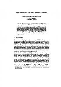
Figure 2.15: Optimized Filtering Block for 2D Median filter [83]
Used Hardrware Resources 1000 100 10 1
Slice Registers
LUTs
DSP slices
Reconfigurable IP
408
1530
21
Dedicated Circuits
692
1902
81
Figure 2.16: Resource Utilization Compared to Dedicated Circuits
31
Power (W)
CHAPTER 2.
0.9 0.8 0.7 0.6 0.5 0.4 0.3 0.2 0.1 0
ACCELERATING RECONFIGURATION OF DSP-BASED CIRCUITS
32
0.335 0.291
StaFc Power 0.468
Dedicated Circuits
Dynamic Power 0.402
Reconfigurable IP
Figure 2.17: Static and Dynamic Power Consumption Compared to Dedicated Circuits and Mean filters. As shown in Figure 2.18, the circuit merges the different functions in one reconfigurable unit following ARENA approach. The configuration circuit is not represented in Figure 2.18. Its role consists of applying beforehand stored configuration vectors according to the desired circuit. Hence, the reconfiguration occurs by assigning different DSP slices functionality as well as MUXs’ select signals thereby determining the overall circuit performed function. The comparing circuit is a unit used to implement the median filter. It is worth noting that the median filter architecture is the optimized architecture proposed by [83] in which the comparison circuit forwards only necessary operands comparisons. Hence, the signal inf i ∀i corresponds to the results (inferior or superior value) of the comparison operation that is implemented using DSPi . Figure 2.15 corresponds to the implemented median filter architecture. The signals Ci correspond to the different filters coefficients and they are affected depending on the configuration.
CHAPTER 2.
ACCELERATING RECONFIGURATION OF DSP-BASED CIRCUITS
33
Figure 2.18: Architecture of the reconfigurable DSP-based architecture implementing FFT, FIR, Convolution, Median and Mean Filters
CHAPTER 2.
2.6
ACCELERATING RECONFIGURATION OF DSP-BASED CIRCUITS
34
Resource utilization and Power Consumption
In this section, we evaluate the gain obtained by applying ARENA reconfiguration technique in terms of power consumption and hardware resource utilization. For this purpose, we design the different SP kernels cited above separately in Dedicated circuits. The circuits are designed using Xilinx Vivado Design suite 2013.1. The comparison with ARENA presented in Figure 2.16 shows that the proposed approach allows a reduction by 41%, 19% and 74% in Registers, LUTs and DSP48E1 slices respectively. Accordingly, in terms of power consumption, Figure 2.17 shows that implementing circuits using ARENA reduces both static and dynamic power considerably.
2.7
Conclusions
In this chapter, ARENA, a high-speed reconfiguration technique for DSPbased circuits is proposed. It offers a good performance/flexibility compromise and overcomes the reconfiguration bottleneck in conventional FPGAbased designs. The efficiency of the proposed technique is exhibited by the implementation of two dynamically reconfigurable widely used circuits, namely, a reconfigurable coprocessor and a SP unit merging a set of common filters. In addition to the high-speed reconfiguration, achievements in area and power efficiency are performed by DSP48E1 slices sharing. We also provide a custom design tool that generates the reconfigurable circuit as well as the different configuration vectors corresponding to the performed functions.
Chapter 3
Self Adaptive Redundancy for Reliable Obstacle Detection Systems
In this chapter, we propose a cross-layer model of circuits vulnerability. We then use this model to build a self adaptive fault tolerant architecture (ARDAS) that protects only vulnerable parts of the system.
3.1
Introduction
Technology scaling has enabled fabulous improvements in embedded systems performance. Nevertheless, as transistor gate dimensions decrease to the nanometer scale, electronic systems become highly susceptible to environmental-factors-induced errors. Soft errors are caused by single event transients (SETs) that temporarily corrupt data stored in memory cells, or change the state of internal combinational circuit nodes, thereby causing errors to propagate to subsequent parts of the circuit [19]. SETs are voltage transients due to cosmic rays that ionize atoms and generate tracks of electron-hole pairs in semiconductor material. Excess charge along these tracks collects at p-n junctions and causes a circuit’s state or behavior to temporarily change [98]. In addition to increasing operating frequencies and lower voltage levels, shrinking transistors size exacerbates the problem by decreasing the capacitance per transistor. This in turn reduces the critical charge sufficient to flip the data stored in memory cells or corrupt combinational gates outputs. The impact of SETs on SRAM
35
CHAPTER 3.
SELF ADAPTIVE REDUNDANCY FOR RELIABLE OBSTACLE DETECTION SYSTEMS36
cells, latches, flip-flops, and sequential circuits reliability has been extensively studied. Nevertheless, their impact on combinational circuits is still an open problematic. In fact, the capacity of particle-induced pulses to propagate across combinational circuits increases the problem complexity [40]. Shrinking transistor sizes, increasing operating frequencies, and lower voltage levels are increasing the vulnerability of combinational circuits to soft errors and undermining their reliability. For embedded systems in trains and railway infrastructure the situation is even worse. Trains and the corresponding infrastructure operate in a complex and non-homogeneous environment. The railway environment is polluted by electromagnetic fields and low power electronics embedded systems must operate closer to components with very high voltages and currents from trains. To design efficient fault tolerant electronic systems, an accurate estimation of circuits failure rates is a crucial step. The masking phenomenon is one of the fundamentals involved in failure rates estimation within semiconductor circuits. Traditionally, as illustrated in Figure 3.1, three masking mechanisms preventing combinational circuits from soft errors have been considered [41]: logical masking, electrical masking and latching-window masking. Logical masking (LM) happens when an error propagates to reach a gate’s input while another input is in controlling state within the same gate: A ”0” input of a NAND gate is an example. For example, if one input of a NAND gate is equal to logic 0, an error on the gate’s second input will be masked. Electrical masking is due to the electrical properties of the gates crossed by the radiation-induced pulse. It happens when the voltage transient resulting from a particle strike is attenuated by subsequent logic gates because of the electrical property of the gate [66]. In this case, the pulse is masked before reaching the sequential element. When a transient pulse survives from logical masking and electrical masking, it can reach a sequential element either inside or outside its clock window. Pulses that occur inside the clock window are latched and propagate to the rest of the circuit. Latching-window masking, or temporal masking, happens when the transient pulse occurs outside of the latching window for the subsequent sequential element. A latching window is a duration bounded by the setup time and hold time around the active clock edge of an edge-triggered
CHAPTER 3.
SELF ADAPTIVE REDUNDANCY FOR RELIABLE OBSTACLE DETECTION SYSTEMS37
latch [41]. In addition to the three common masking mechanisms, the transistor level architecture of a struck gate can inhibit the error propagation into the struck gate’s output. In fact, as explained later in Section 3.1, a particle strike can be masked through a Transistor-Level-Masking (TLM) mechanism if a corruption in the struck transistor behavior does not affect the overall gate output. TLM depends on the specific affected transistor location within the struck gate and by the input combination during the transient event. In this Chapter we analyze the TLM mechanism and propose a SPICE simulation-based model that estimates the probability of TLM at circuit level. We generalize the model to the gate level and we include logical masking to build an input-dependent model of soft error masking. In addition to the circuit level study, we also extend our focus to system level masking mechanisms in order to build a cross-layer reliability analysis. In fact, we notice that a multitude of classification, detection and recognition applications are based on the comparison of a computed value with a beforehand fixed threshold. Hence, as explained in Section 3.2, an accidental modification in the intermediate result may keep the overall system decision unchanged depending on the detection threshold value. Thereby, a bit flip in a computational block does not necessarily lead to an erroneous result. Based on this observation, we propose a model for System Level Masking (SLM) in threshold-based systems. The proposed cross-layer approach helps designers to quantify the actual vulnerability of their systems and consequently allows them to build reliability enhancement techniques with lower overheads. Traditionally, numerous hardened circuits against soft errors have been proposed. They can be classified into two main families, namely spaceredundancy and time-redundancy approaches. While time redundancy results in a considerable performance penalty, the main weakness of spatial redundancy is the huge area (and consequently power consumption) overhead. In this Chapter, we present ARDAS: Adjustable Redundancy in DSP-based Architectures for Soft errors resiliency, an architecture that uses adjustable redundancy of DSP blocks to protect the vulnerable circuit parts instead of protecting the whole circuit. The vulnerability analysis is performed through design-time simulations that implement the proposed masking models (TLM
CHAPTER 3.
SELF ADAPTIVE REDUNDANCY FOR RELIABLE OBSTACLE DETECTION SYSTEMS38
and SLM). The cross-layer aspect of our approach leads to an accurate estimation of the circuit requirements in terms of reliability. We validate the proposed analysis on a DSP-based correlator dedicated to RADAR-based obstacle detection. Based on the estimation of vulnerability and taking advantage from the DSP slices flexibility, we dynamically affect the redundant DSPs to the highly susceptible DSPs to soft errors. Unlike TMR reliability enhancement technique, the redundant hardware resources in ARDAS are shared between different parts of the circuit and the redundancy map can be changed at run-time depending on the input combination to fit to the vulnerability level of the different slices. The main contributions of this Chapter are: 1. A SPICE simulation-based probabilistic model of TLM in combinational circuits. 2. A SLM model for threshold-based applications. 3. A cross-layer vulnerability analysis based on the proposed masking models (TLM and SLM). 4. We propose ARDAS and validate it on a radar-based obstacle detection system for railway transportation control to build a low cost reliable system. The rest of the chapter is organized as follows. In Section 3.2, we provide the necessary background as well as a brief review of the literature on soft errors, masking mechanisms and fault tolerance techniques. TLM and SLM mechanisms modeling are explained in Section 3.3. In Section 3.4, we detail ARDAS architecture while the experimental results of its application on an obstacle detection circuit in railway transportation are shown in Section 3.5. Finally, we conclude the Chapter and provide possible perspectives for our work.
CHAPTER 3.
SELF ADAPTIVE REDUNDANCY FOR RELIABLE OBSTACLE DETECTION SYSTEMS39
Figure 3.1: Three soft error masking mechanisms
3.2
Background and Related Works
3.2.1
Soft Errors in Combinational Circuits
Many works on SER estimation in logic circuits have been recently proposed [93, 94, 95]. Fault simulation method [39], Binary Decision Diagrams (BDDs) and Algebraic Decision Diagrams (ADDs) [23] based techniques have been proposed to estimate the LM effect. Latching window mechanism has been modeled accurately in [32] and the authors in [36] introduce the concept of Window Of Vulnerability (WOV) to analyze temporal masking effect. Electrical masking effect has been studied in [39] and the authors suggest an accurate model based on the nonlinear properties of sub-micron MOS transistors for soft error tolerance analysis taking into account electrical, logical and latching window masking. While [95] [39] and [33] separately evaluate the impact of electrical, logical and latching window masking phenomena, the authors in[76] propose MARS-C, a framework that provides a unified representation of the three masking techniques. In [93], a symbolic technique for estimating scaling error probability named FASER is proposed. FASER can be applied to logical and electrical masking and takes clock frequency into account. Recently, process variation has become an issue and introduced new chal-
CHAPTER 3.
SELF ADAPTIVE REDUNDANCY FOR RELIABLE OBSTACLE DETECTION SYSTEMS40
lenges in the estimation accuracy of SER. A Statistical SER analysis that has been presented in [33] [73] takes into account the impact of process variation on the chip and models the three masking mechanisms. All the cited references analyze the masking mechanisms as a key metric for SER estimation in combinational circuits. In our work, we consider a masking mechanism that inhibits the radiationstrike-induced pulse in combinational circuits at the transistor level due to the gate architecture. As we explain later, we implement our correlation circuit using DSP48E1 slices to take advantage of their high performance on the one hand, and their flexibility on the other. We also profit from their programmability to develop a dynamic-redundancy-based fault tolerance technique.
3.2.2
Reliability Enhancement Techniques
In the literature, the most widely used reliability enhancement approaches are: spatial redundancy and temporal redundancy. Spatial redundancy is implemented by carrying out the same computation on multiple and independent hardware units simultaneously. The most common spatial redundancy method is TMR in which a circuit is replicated three times and Majority Voters (MVs) are used to select the correct result and mask erroneous values. The main disadvantage of this method is its significant area and power overheads. The second class of spatial redundancy techniques replicates critical nodes and uses feedback to recover the correct value after an upset. The above technique is used in the immune cells that include the Heavy Ion Tolerant (HIT) cell [36]. Another alternative to hardware redundancy is time redundancy. This approach achieves redundancy by repeating the same operation multiple times on the same hardware. A recent Double Time Redundancy (DTR) technique has been proposed [29] as an alternative to Triple Time Redundancy that trades-off the circuit throughput for a considerable hardware overhead. Time redundancy technique greatly reduces the hardware cost, but incurs high time penalty and consequently high performance loss.
CHAPTER 3.
3.3 3.3.1
SELF ADAPTIVE REDUNDANCY FOR RELIABLE OBSTACLE DETECTION SYSTEMS41
Input-dependent Masking Mechanisms TLM: Transistor-Level Masking Mechanism
TLM occurrence is led by the affected transistor locality within the struck gate as well as the input combination during the transient event. In fact, the particle strike temporarily corrupts combinational elements by affecting the state of the hit transistor. However, the event can be simply unnoticed at the output if the transistor behavior corruption doesn’t affect the overall state of pull-up/pull-down network. For example, a faulty state of one of two parallel pmos transistors in depletion mode doesn’t change the pull-up network state. Consequently, the fault is inhibited at transistor level. It is worth noting that in this chapter, we consider single event transients and suppose that the transient strike footprint doesn’t exceed one hit transistor. In fact, it has been shown in [96] that the maximum range of particle strike induced EHP radius is equal to 20 nm which is lower than the transistor dimensions in the considered technology (45 nm). Although both TLM and LM depend on the input data, their mechanisms are totally different. Two main differences are cited below: • Masking locality: the particle induced pulse in TLM case does not propagate to the struck gate output and is masked within the internal gate architecture. Hence, no subsequent gate is needed for error masking by TLM. However, in logical masking the pulse propagates through the struck gate’s output and is masked later by a subsequent gate if the error-free input is in a controlling state. • Masking conditions: while TLM depends on both input combination and struck transistor location within the gate architecture, LM depends only on the error-free input of the subsequent gate to the struck one and is totally independent from which transistor is hit. Several algorithms in test-oriented studies modeled masking mechanisms at transistor level within CMOS circuits. The considered cases in these works correspond to permanent faults and are referred to as stuck-open and stuckshort faults [67] [43]. Nevertheless, although soft errors masking mechanisms
CHAPTER 3.
SELF ADAPTIVE REDUNDANCY FOR RELIABLE OBSTACLE DETECTION SYSTEMS42
have been extensively investigated, to the best of our knowledge there are no published works that model the transistor level masking of transient errors in combinational circuits. For illustration, let’s consider the 2-input CMOS NAND gate shown in Figure 5.3. Assume a radiation strike has upset the PMOS transistor Q3 of the NAND gate. The behavior of this transistor is corrupted if the collected charge due to a strike is greater than the node’s critical charge. Nevertheless, if the input-combination is 00 then the second p-transistor (Q4) is activated and it connects the output to Vdd even if Q3 doesn’t. Consequently, the NAND gate output is not affected by the transient event and the output remains at logic state 1 just like an error-free NAND gate. While in TLM, the gate output is correct, LM corresponds to a corrupted output data that is going to be masked later by a subsequent gate (not struck by the radiation) whose result is completely determined by its other input values. However, if the input combination is 01 then a strike-induced upset in transistor Q3 will switch off this latter and break the link of the output to Vdd. The error is in this case propagated and the output flips from 1 to 0. Therefore, in addition to the three common masking mechanisms presented in Section 1, the error propagation depends also on the position of the struck transistor within the gate and the input data. To validate the TLM mechanism, we ran HSPICE simulations by injecting a current pulse at the different gate nodes to emulate the injected pulse during a single event. The impact of the simulated event is noticed on the gate output for the different input combinations. We simulate gates behavior using a 45 nm technology file from PTM [6]. Probability of TLM To quantify TLM mechanism’s impact on gates susceptibility to soft errors, we calculate the probability of soft error masking due to TLM for a given gate based on the results obtained from Section 3.1. This probability is named here PT LM . Let be Di a binary indicator for a given gate that shows if the error due to a particle strike hitting a transistor Qi is masked by a TLM mechanism. Di equals 1 if the particle strike hits the transistor Qi without
CHAPTER 3.
SELF ADAPTIVE REDUNDANCY FOR RELIABLE OBSTACLE DETECTION SYSTEMS43
Figure 3.2: TLM Example: Radiation strike hitting PMOS transistor Q3 in a Nand 2 gate within a C17 circuit. The error is masked when the inputs are at ”00” corrupting the output (TLM case), and 0 if the strike in Qi results in a corrupted output. During an event, Pi is the probability that a transistor Qi is hit by the particle. Hence, the probability that the error resulting from a radiation strike is masked is equal to the sum of the probabilities Pi when the affected transistor state Qi has no impact on the output. The probability of a soft error TLM Pm for a given input combination is then expressed by: NT X Pm (out) = (Pi ∗ Di )
(3.1)
i=1
For a simplification reason, we suppose the equiprobability to be hit by the particle strike between all the infected gates’ transistors. Pi is then constant and is given by:
Pi =
1 NT
(3.2)
CHAPTER 3.
SELF ADAPTIVE REDUNDANCY FOR RELIABLE OBSTACLE DETECTION SYSTEMS44
TABLEAU 3.1: Probabilities of TLM of a NAND, XOR and AND logic gates for the different input combinations
Nand 00 01 10 11
100 50 50 0
Xor
And
33.33 66.67 33.33 33.33 33.33 33.33 50 0
Where NT is the number of transistors in the considered gate. Let Nm be the number of cases the error is masked for a given input combination. Then equation 3.1 becomes:
Pm (out) =
Nm NT
(3.3)
Table 3.1 shows the results of the SPICE-based probabilistic model detailed above applied to two-input NAND, XOR and AND gates. It is clear from the exposed masking probabilities that the impact of the TLM mechanism on soft error rates in logic gates is not negligible. in the case of a 00 input to the NAND gate, the probability of TLM reaches 100% which means that in this case the gate is totally radiation-induced fault tolerant. Therefore, taking this masking effect into account in the SER estimation of combinational circuits will remarkably improve prediction and avoid possible overheads in the soft error mitigation techniques. The next Section generalizes the probabilistic model to the gate level. Then, we examine the C17 benchmark and a 4 × 4 multiplier circuit in order to quantify their vulnerability to soft errors taking into account the TLM effect. Probabilistic Model In this Section we examine soft error masking at the gate level. We suppose that a particle hits a combinational circuit and produces a pulse that is large enough to survive electrical and latching window masking. Hence we model
CHAPTER 3.
SELF ADAPTIVE REDUNDANCY FOR RELIABLE OBSTACLE DETECTION SYSTEMS45
the propagation of the transient radiation induced error while considering both TLM and LM mechanisms. If Si is the ith bit of the circuit output S then, given the assumption above, the SET has no impact on Si in three cases: 1. By TLM mechanism: if the error is masked at transistor level as shown in the previous Section. 2. By LM mechanism: if the error survived from the TLM and forwarded to a ”don’t care” input of a subsequent gate. 3. If the error survived from the two previous mechanisms and propagated to an output (or more) other than Si . Hence, the probability of soft error masking in the output bit Si for a given input combination is:
Pm (Si ) =
n X j=1
Wj · (PT LM (j) + (1 − PT LM (j)) · Dij )
(3.4)
Where: 1. n is the number of gates in the combinational circuit, 2. PT LM (j) is the probability of TLM fr a gate j, and 3. Wj is the weight assigned to gate j and represents the area fraction. Wj is expressed as the number of the gate’s transistors divided by the total number of transistors in the circuit. 4. Finally, Dij is a binary variable set to 1 if the error at gate j does not propagate to output Si . It is set to 0 otherwise. Algorithm 2 calculates the probability of soft error masking at the circuit outputs for a given input combination. Note that the golden run output Sc (i) the output bit is compared with the bit under fault injection. This latter corresponds to a circuit node bit flip. The output bit is then compared with the golden run output Sc (i).
CHAPTER 3.
SELF ADAPTIVE REDUNDANCY FOR RELIABLE OBSTACLE DETECTION SYSTEMS46
Algorithm 2 Compute probability of error masking for an input combination Ic Function ProbaMask() Inputs: Circuit, Input Signals :Ic Outputs: Pm for i = 1 ..
m do
/*m is the number of output bits*/ Pm (i) ← 0 /* Initialize probability of masking output i */ for j= 1.. n do n is the number of gates injectError(j) /* Inject error in gate j */ if Si∗ = Si then Dij ← 1 /* the error is masked */ else Dij ← 0 end end Pm (i) ← Pm (i) + W (j) × (PT LM (j) + (1 − PT LM (j)) × Dij
end
end Return (Pm ); We implemented the proposed model in the C language to simulate the circuit’s error-free and faulty behaviors. We compute the masking probabilities for input combinations. We first show the results corresponding to the C17 circuit from the ISCAS’85 benchmark. Then, we run the simulation for a full adder circuit and a 4 × 4 multiplier which corresponds to a simplified version of the ISCAS’85 C6288 benchmark. Results for C17 benchmark: To highlight the TLM effect on combinational circuits, we study the ISCAS’85 benchmark C17 circuit shown previously in Fig 5.3. As the probability of both TLM and LM mechanisms directly depends on the circuit input vector, we compare the impact of TLM
CHAPTER 3.
SELF ADAPTIVE REDUNDANCY FOR RELIABLE OBSTACLE DETECTION SYSTEMS47
on the circuit outputs vulnerability to soft errors with LM. The results shown in Figure 3.3 demonstrate that TLM is, in most cases, more effective in restricting soft error propagation than LM. In fact, for more than 59% of the input combinations, the outputs mean probability of error masking due to TLM is higher than LM probability. TLM and LM probabilities for C17 benchmark 0.6 TLM
LM
0.5 0.4 0.3 0.2
11111
11110
11101
11100
11011
11010
11001
10111
11000
10110
10101
10011
10100
10010
10001
01111
10000
01110
01101
01100
01011
01010
01001
00111
01000
00110
00101
00011
00100
00010
00001
0
00000
0.1
input vector
Figure 3.3: TLM and Logical Masking (LM) probabilities for the C17 benchmark Results for a full adder: We run the simulations to explore the TLM of a full adder circuit. The results shown in Figure 3.4 correspond to the four possible cases: 1. 2M: the fault is masked at the two outputs (S and Cout ) and the 2 output are valid . 2. SM CE: the fault is masked at the S output, but not at Cout . In this case, S is valid but Cout is erroneous. 3. SE CM: the fault is masked at the Cout output, but not at S. In this case, S is erroneous but Cout is valid. 4. 2E: the fault is not masked and both outputs are erroneous.
CHAPTER 3.
SELF ADAPTIVE REDUNDANCY FOR RELIABLE OBSTACLE DETECTION SYSTEMS48
Full Adder TLM Probabilities 0.6 0.5
TLM Probability
0.4 0.3 0.2 0.1 0 '000
'001
'010
'011
'100
'101
'110
'111
Input Combination 2M SM_CE SE_CM 2E
Figure 3.4: Different masking probabilities of a full adder. The 3 input-bits correspond respectively to Cin ,Y and X. Figure 3.4 shows that the probability that the two output bits of a particle-struck full adder circuit are masked by TLM mechanism is between 0.4 and 0.5. Results for 4 × 4 Multiplier: Figure 3.5 shows the 4 × 4 multiplier architecture that is considered in this section. The multiplier is built using AND gates and adders while the full adder circuit is composed of two AND, two XOR and one OR gates. Hence, we first implemented the algorithm for the full adder to measure the masking probabilities of the outputs at the sum and carry-out outputs. Different input combinations were considered. Based on the adder’s results, we identify the masking probabilities of the multiplier outputs. The results shown in Figure 3.6 correspond to four significant input combinations illustrating the behavior of the masking probability in terms of input values. These results prove that the TLM has a considerable impact on the SER estimation in combinational circuits. In fact, depending on the input vector, a soft error may have a masking probability that can reach 47% for a 4 × 4 multiplier. Hence, this information is valuable for analyzing combinational circuits susceptibility to soft errors and consequently for circuit reliability estimation.
CHAPTER 3.
SELF ADAPTIVE REDUNDANCY FOR RELIABLE OBSTACLE DETECTION SYSTEMS49
Figure 3.5: Architecture of a 4 × 4 multiplier Probability of output error masking and VF for a 4x4 multiplier
Masking probability (%)
60 50
S0 S1 S2 S3 S4 S5 S6 S7
40 30 20 10 0 0x0
0x9
15x0
15x15
Input combination samples
Figure 3.6: Masking probabilities of a 4 × 4 multiplier. S0 to S7 correspond to the outputs.
3.3.2
SLM: System-Level Masking Mechanism
Modeling SLM Figure 3.7 shows a simplified threshold-based system that is composed of a processing element and a comparator. The comparison of the intermediate result with a beforehand fixed threshold gives the overall system decision. For example, the intermediate result in the radar-based obstacle detection system considered in Section 5 consists of a correlation between input and
CHAPTER 3.
SELF ADAPTIVE REDUNDANCY FOR RELIABLE OBSTACLE DETECTION SYSTEMS50
Threshold
Input Signals
Processing Element
Intermediate Result
System Result
Figure 3.7: General Architecture of a Threshold-based System reference signals. Hence, a transient error in the intermediate result may keep the overall system decision unchanged depending on the detection threshold value. Thereby, a bit flip in a computational block does not necessarily lead to a system failure. Based on this observation, we propose an in-depth study of System Level Masking (SLM) impact in threshold-based systems to investigate the impact of soft errors at system level. To this end, we consider a widely used signal processing element in detection/recognition applications, namely, a correlator. It is worth noting that the same methodology can be applied on any other computing element of a threshold-based application. We built a simulation platform that tracks the propagation of particle-strikeinduced errors happening within the correlator nodes and evaluated their impact on obstacle detection accuracy. The correlator is implemented using DSP48E1 slices [1]. Consequently, the considered nodes of the circuit are the different output bits of the DSPs. A soft error is modeled by injecting a bit flip in one of the circuit nodes. Once a fault is injected, the platform simulates the error propagation in the circuit until the correlation output. Hence, the system behavior can be monitored under fault injection through system failures (SFs) detection. A SF occurs in two cases: 1. False Alarm: If the output after fault injection exceeds the correlation threshold while the initial output value, i.e. without fault injection, is lower than the threshold. This situation corresponds to a ”false alarm”. 2. No Alarm: A ”no alarm” case occurs if the injected fault transforms the correlation result from higher than the threshold to lower than the
CHAPTER 3.
SELF ADAPTIVE REDUNDANCY FOR RELIABLE OBSTACLE DETECTION SYSTEMS51
threshold. It corresponds, in an obstacle detection system, to a nondetected obstacle. To identify SFs, we introduce an indicator δij that is expressed by: δij = (Cij ∗ − Y0 ) · (C − Y0 )
(3.5)
Where Cij ∗ is the correlation result under fault injection in node (i, j), C is the error-free correlation result and Y0 is the correlation threshold. The circuit behavior under fault injection is then observed at the system level via δij . A SF occurs when δij < 0. In this case the injected error propagates through the circuit and manifests into the output as one of the two SF cases mentioned above. However, if δij ≥ 0 we have a System Level Masking (SLM). In this case, the injected error didn’t lead to a SF and it has been masked at the system level. For a node (i, j) corresponding to the output bit i of DSPj , depending on the sign of the corresponding δij , we identify wether an obstacle detection failure is induced by the injected fault.
3.4
ARDAS:
Adjustable
Redundancy
in
DSP-based Architectures for Soft errors resiliency 3.4.1
Vulnerability Modeling
In the previous Section, we focused on input-dependent masking mechanisms. We model these mechanisms for both circuit and system level. In this Section, we combine the two masking mechanisms, TLM and SLM, to evaluate the effective vulnerability of the system. For a node (i, j), we define ηij , as an indicator of SLM. The variable ηij is equal to 0 if a fault at node (i, j) is masked at the system level (i.e. δij ≥ 0). Otherwise, if δij < 0, ηij is equal to 1. To measure the susceptibility of the circuit to transient errors and their impact on the overall system behavior, we need to take into account both circuit level and system level susceptibility to errors. Hence, we define the vulnerability of a DSPj as the mean value of
CHAPTER 3.
SELF ADAPTIVE REDUNDANCY FOR RELIABLE OBSTACLE DETECTION SYSTEMS52
Get the Input Signals
TLM Model
SLM Model
Pij
ηij
Vulnerability Analysis
Vj>V0?
αj = 0
αj = 1
DSPj is Vulnerable
DSPj is not Vulnerable
Figure 3.8: Simulation flowchart the probability that a soft error manifests to its output bit i weighted by the SLM indicator ηij . The vulnerability Vj is expressed by: PNj Vj =
i=1
ηij · (1 − Pij ) Nj
(3.6)
Where: • Nj is the number of output bits of DSPj • Pij is the probability of soft error masking relative to bit i of DSPj obtained through Algorithm 1. Note that Vj = 1 corresponds to a vulnerable DSP and highly susceptibility to soft errors. This case occurs when the following conditions take place: ∀i ∈ [1; Nj ], Pij = 0 and ηij = 1
CHAPTER 3.
SELF ADAPTIVE REDUNDANCY FOR RELIABLE OBSTACLE DETECTION SYSTEMS53
In other words, every particle that hits the circuit survives from TLM and manifests as an error into the output while every bit flip in a node (i, j) leads to a SF. On the other hand, Vj = 0 corresponds to a fully hardened DSP against soft errors: ∀i ∈ [1; Nj ], Pij = 1 or ηij = 0. A DSP in this case does not need any additional circuitry to protect it from SETs. As the two masking mechanisms affecting the vulnerability are input-dependent, Vj of DSPj varies depending on the data input values. Consequently, for every input combination, the circuit vulnerability map is represented by a vector that corresponds to the values of Vj ∀j ∈ [1; Ndsp ]. Where Ndsp is the number of DSP48E1 slices within the circuit. As Vj gives a metric of susceptibility to transient errors, instead of applying TMR to the whole circuit, we use Vj to identify the vulnerable DSP slices and protect them. In the proposed approach, we compare the DSP vulnerability to a fixed threshold V0 and localize the DSPs whose Vj > V0 . The vulnerability threshold V0 indicates the desired reliability level and is fixed by the user at design time. The higher V0 is, the more reliable the circuit becomes. To simplify the representation, we define αj as follows: αj = 0 if Vj > V0 and αj = 1 if Vj ≤ V0 As αj indicates if DSPj is considered as vulnerable or not for a given input combination, we call αj vector: DSPs Vulnerability Distribution (DVD). Hence, for every input combination, the 0 values of the DVD represent the DSPs that need TMR to ensure the whole circuit’s requested level of reliability. The probability of an error manifestation represents the whole circuit susceptibility to soft errors. We call it Global Vulnerability (GV) and express it as follows: P P i j (1 − Pij ) · ηij (3.7) GV = NT Where NT is the total number of nodes within the circuit. Given Vj expression given by Equation 3.6, GV is then expressed by Equation 3.8
CHAPTER 3.
SELF ADAPTIVE REDUNDANCY FOR RELIABLE OBSTACLE DETECTION SYSTEMS54
Transistor Level
Spice Simulations Circuit Results
Gate Level
System Level
Probabilistic Model
Exhaustive Fault Injection
ẟij
Pij
Vulnerability Estimation Vj Desired Reliability Level
Reliability Map Generation
Reliability Map
Figure 3.9: Design Time Cross-layer Exploration Steps
P GV =
j
Vj · Nj NT
(3.8)
Based on TLM and SLM, we run simulations as shown in the flowchart in Figure 4.8 to get Vj , αj and GV . As Vj vector depends on the applied input signals, the redundancy distribution corresponding to the vulnerability map has to be dynamically tunable and self adaptive. The cross-layer design time exploration steps are summarized in Figure 3.9. In the next Section, we explain the reconfigurable redundancy approach.
3.4.2
Proposed Approach
The main idea of ARDAS is to judiciously use the redundant DSP slices to carry out a partial TMR instead of a full TMR. The system adapts the redundancy to the actual vulnerability map of the circuit. Using the circuit’s DVD obtained from design-time simulations, ARDAS assigns redundant slices specifically to vulnerable DSPs, i.e. slices with αj = 0. Hence,
CHAPTER 3.
SELF ADAPTIVE REDUNDANCY FOR RELIABLE OBSTACLE DETECTION SYSTEMS55
in1 in2 in3 in4
DSP1
DSP2
O_dsp1
O_dsp2
dsp1_datapath
dsp2_datapath
Redundant DSP1
Voter
O_correct
Redundant DSP2
Additional Resources
select
Figure 3.10: An illustrative circuit of the flexible redundancy used in ARDAS
unlike the conventional TMR approach, the redundant resources in ARDAS are shared between the different original circuit’s DSP slices and dynamically assigned to the vulnerable parts. The reuse of redundant resources by different DSPs avoids the huge area overhead found in conventional TMR. Figure 3.10 illustrates a DSP-based architecture with flexible redundancy. The redundant DSP slices can be dynamically affected to one of the initial DSPs to enhance its reliability. The interconnection is controlled through the ”select” signal to route the redundant hardware according to the corresponding reliability map. Hence, instead of tripling all DSP blocks as commonly done in TMR, only vulnerable DSPs are protected. The protected circuit is composed of the original DSPs and a set of additional slices that are dedicated to improve the original system reliability. The number of redundant DSP slices used for the whole circuit, and covering all input combinations, is determined at design time simulations. It depends on the requested reliability level and consequently on the vulnerability threshold V0 . For a given input combination, the number of additional DSPs is twice
CHAPTER 3.
SELF ADAPTIVE REDUNDANCY FOR RELIABLE OBSTACLE DETECTION SYSTEMS56
the number of zeros in the αj vector as a DSP needs two redundant slices to be protected. Hence, the overall number of redundant slices is the maximum redundant DSP number among all tested input signals. The reconfiguration process used to change the redundancy mapping at run-time is taken from Chapter 2. Using the proposed reconfiguration technique, the DSP network can be reconfigured in a single clock cycle allowing to quickly switch between different redundancy maps at run time. Reprogramming and routing the DSP48E1 slices enables us to modify the structural organization and functionality of the DSP-based circuit. The circuit mapping is configured by a single control word according to a redundancy map obtained offline through design-time simulations. The bit fields of a configuration vector determine the structural organization of the redundant DSP blocks by enabling the interconnection paths that organize slices within specific vulnerable structures. ARDAS architecture assigns TMR to all DSP slices with αj = 0. Consequently, if we suppose that a TMR-protected DSP slice is fully hardened (Vj = 0), the GV expression becomes: PNdsp GV =
j=1
Vj × Nj × αj NT
(3.9)
In Figure 3.11 we show the impact of the vulnerability threshold (V0 ) on the GV and the number of redundant DSPs. The results are shown for a correlation circuit with the characteristics presented in Table 3.2. In near 0 vulnerability threshold values, all DSP slices are considered vulnerable and we fall in a conventional TMR case. Nevertheless, increasing V0 leads to a reduced number of redundant DSPs and consequently to rising circuit GV. Note that a range of V0 can keep the GV unchanged depending on the DSP slices elementary vulnerabilities Vj .
CHAPTER 3.
SELF ADAPTIVE REDUNDANCY FOR RELIABLE OBSTACLE DETECTION SYSTEMS57
GV and DSPs number vs V0 180
0.7 0.6
140 0.5
120 100
0.4
80
0.3
60
0.2
40
Global Vulnerability (GV)
Number of redundant DSPs
160
0.1
20 0
0 0
0.1
0.2
0.3
0.4
0.5
0.6
0.7
0.8
0.9
1
Vulnerability Threshold (V0 ) Number of Redundent DSPs
Global Vulnerabilty (GV)
Figure 3.11: Redundant DSPs and Global Vulnerability in terms of Vulnerability Threshold
TABLEAU 3.2: The correlation circuit characteristics
Number of inputs 80 (2 sets of 40 samples) Input sample length 8 bits Output word length 22 bits Nbr of DSPs (original circuit) 79
CHAPTER 3.
3.5
SELF ADAPTIVE REDUNDANCY FOR RELIABLE OBSTACLE DETECTION SYSTEMS58
Application Case: Obstacle Detection in Railway Infrastructure Control System
The railway environment constitutes one of the most aggressive operating conditions of embedded systems. Moreover, electronic systems implement a continuously increasing number of applications for several purposes such as safety, users comfort...etc. Therefore, a cost-aware reliability enhancement of the hardware supporting those applications is a crucial task. In this section, we present the application of ARDAS on a radar-based obstacle detection system dedicated to critical spots surveillance in a railway infrastructure. The general architecture of a radar-based obstacle detection system is shown in Figure 3.12. It consists of 3 functional units: the UWB radar, the signal preprocessing and the correlation circuit. In the following experiments, a Gegenbauer-pulse-based Ultra Wide Band (UWB) radar with 3 GHz bandwidth is used. The radar scans periodically with a time of 25 ms. At the reception, the sampling procedure and the Analog Digital Conversion (ADC) are first performed. An impulse signal S˜ is periodically sent by the Radar ˜ corresponds to a vector of N ˜ samples: transmitter. The reflected signal R ˜ = {˜ R r0 , · · · , r˜N˜ −1 }. R0 is the reference signal and corresponds to the impulse signal transmitted from the transmission antenna Tx to the reception ˜ -element vector R0 = {r00 , · · · , r0 ˜ } [71][92]. antenna Rx. It is a M M −1 ˜ and R0 is calculated to deterAt the reception, a correlation between R mine first the obstacle distance (equation 3.10).
˜ ⊗ R0 ) = Td = fc (R
˜ −1 M ˜ −1 N X X i=0 j=0
(˜ ri+j × rj0 )
(3.10)
The signals shown in Figure 3.13 correspond to the registered signature of radar signals corresponding to the most frequently encountered obstacles at the considered location, namely: train, car and pedestrian signals, respectively. These signatures have been collected in ideal situation with reduced noise. An overall view of the correlation circuit with ARDAS architecture is shown in Figure 3.15.
CHAPTER 3.
SELF ADAPTIVE REDUNDANCY FOR RELIABLE OBSTACLE DETECTION SYSTEMS59
S~)
R)
Filtering))
Sampling)&)ADC) R~) R’)
Obstacle) Detec3on)
Correla3on)
Figure 3.12: A general architecture of an obstacle detection system
8
8
6
6
1.5
1
4
4
2
2
0.5
0 0
0 −2
−2
−4
−0.5
−4
−6
−1
−6
−8 950
1000
1050
1100
1150
1200
a) Train Signal
1250
650
700
750
800
850
900
b) Car Signal
950
900
950
1000
1050
1100
c) Pedestrian Signal
Figure 3.13: Different raw signals for three frequently faced obstacles
CHAPTER 3.
SELF ADAPTIVE REDUNDANCY FOR RELIABLE OBSTACLE DETECTION SYSTEMS60
In our experiments, the noisy frequencies with high amplitudes are filtered before being applied to the correlation circuit inputs. In order to study the noise impact on our system’s output, we assume that the remaining noise signals after filtering follow a normal distribution. Based on experimental measurements, we identify the mean value and the standard deviation thereby realizing that 95% of the noise samples can be encoded on two bits. As a matter of fact, the evaluation of the noise impact on the circuit vulnerability map is noticed in the cases corresponding to the ”near correlation threshold” set. Hence, for every input obstacle signal corresponds a vulnerability map selected by the six most significant bits of the input samples. A default configuration is set in case of none of the predefined cases matches with the input. In our experiments, the default map was chosen by setting the multiplexers select signals to ”0”.
3.5.1
Reliability Enhancement
1 0.9
140
Normalized SER
0.8
120
0.7
100
0.6 0.5
80
0.4
60
0.3
40
0.2
20
0.1 0
0 0
0.1
0.2
0.3
0.4
0.5
0.6
0.7
0.8
0.9
1
Number of redundant DSPs (for ARDAS)
In this section, we compare the SER of ARDAS-protected to a TMRprotected correlation circuit as it gives the highest error mitigation level. We report the evolution of the reliability level provided by ARDAS in terms
Vulnerability Threshold Number of redundant DSPs
Full TMR SER
ARDAS SER
Raw Circuit SER
Figure 3.14: Normalized SER for the three correlation circuits: Original, with ARDAS and with TMR. Used DSP resources in terms of V0 is also given.
CHAPTER 3.
SELF ADAPTIVE REDUNDANCY FOR RELIABLE OBSTACLE DETECTION SYSTEMS61
in1 ref1 in2 ref2
RX Obstacle
8 8 8 8
Input Preprocessing
ORIGINAL CIRCUIT
TX in40 ref40
Reference Signals
8 8
Redundant DSPs
Interconnection
Reconfiguration Controller
Reliability Maps
Design Time Explorations
Figure 3.15: Overall Correlation circuit with ARDAS architecture
of V0 . SER is commonly expressed in Failure in Time (FIT) and defines the expected number of errors in 109 hours at a given environment. In our case, we are considering the neutron flux at New York (NY) as reference (13n/(cm2 .h)) [4]. FIT is the product of the flux with the cross-section. It is described in the following expression: SER =
SF ∗ (13n/(cm2 .h)).109 particles/cm2
(3.11)
Where cross-section quantifies the sensitivity of the implemented circuit to a specific radiation source [86] and is defined as the ratio between the number of SETs producing a system failure (SF) and the number of hitting particles. As the reliability level is tuned via V0 , Figure 3.14 represents the normalized SER and the number of used DSP slices in ARDAS in terms of the tolerated DSP vulnerability threshold. As seen in Figure 3.14, the reliability level provided by ARDAS is comparable to TMR reliability level but with lower HW resource utilization. In
One Dataset Execu-on Time (us)
CHAPTER 3.
SELF ADAPTIVE REDUNDANCY FOR RELIABLE OBSTACLE DETECTION SYSTEMS62
0.1 0.09 0.08 0.07 0.06 0.05 0.04 0.03 0.02 0.01 0 Maximum Frequency
Original
TMR
Frequency=150 MHz
DTR
ARDAS
Figure 3.16: Execution time comparison of the different architectures for two different frequency configurations
fact, with a minor rise in the SER offered by TMR, ARDAS can preserve more than 50% of the additional DSPs dedicated to enhance the circuit’s reliability when V0 = 0.7. Therefore, ARDAS offers the designer the ability to choose the desired reliability level at design time through the tolerated vulnerability threshold. Accordingly, the reliability/resource-utilization tradeoff can be carried out depending on the application criticality level.
3.5.2
Power, area and performance overheads
In addition to the reliability, we investigate the impact of ARDAS on power consumption, FPGA resource utilization and the maximum clock frequency of each circuit. For our application, we tested the circuit for two vulnerability threshold values: 0.55 and 0.7. The circuit is implemented using ISE Xilinx v14.1 and synthesized for a Xilinx Virtex 7 board. The power consumption is estimated using the Xilinx XPower Analyser tool [89]. Note that the power consumption results correspond to the circuits running under a frequency of 150 MHz. For our experimentations, we implemented the original circuit, TMR-protected, ARDAS and Double Time Redundancy Transformation (DTR) [29].
CHAPTER 3.
SELF ADAPTIVE REDUNDANCY FOR RELIABLE OBSTACLE DETECTION SYSTEMS63
TABLEAU 3.3: Resource utilization, power and maximum frequency for the original circuit, TMR and ARDAS.
Original TMR ARDAS(V0 =0.55) ARDAS(V0 =0.7) DTR DSPs LUTs Pw(mW) Max freq (MHz)
79 0 430 422
237 1798 691 247
189 1619 542 347
159 1207 533 347
79 1413 459 410
Table 3.3 shows that our architecture can reduce the reliability cost in terms of resource utilization, power and performance. Even though ARDAS implementation uses additional circuitry for its flexible interconnection, the overall fabric utilization remains lower than TMR’s overhead due to majority voters. In fact, ARDAS decreases the number of used LUTs by 10% for V0 = 0.55 and by 32% for V0 = 0.7 compared to TMR. On the other hand, while using TMR slows down the circuit frequency by 42%, ARDAS performance penalty is less than 18% compared to the unprotected circuit. To further investigate the performance impact of ARDAS, we compare the necessary time for one dataset processing of the original circuit, TMR, ARDAS and DTR. Figure 3.16 shows the execution time results for the different circuits in two cases: 1. Each circuit is running under its maximum frequency (given in Table 3.3). 2. All the circuits are running under the same low frequency (150 MHz). Figure 3.16 shows that among the considered reliability enhancement techniques, ARDAS has the highest throughput. In fact, even if its maximum frequency is lower than DTR, this latter suffers from a performance limitation due to the time redundancy penalty. Results in Figure 3.16 and Table 3.3 thereby prove that ARDAS is an interesting alternative to conventional space and time redundancy approaches. In fact, it insures a relevant balance between reliability enhancement overheads in terms of throughput and area.
CHAPTER 3.
3.6
SELF ADAPTIVE REDUNDANCY FOR RELIABLE OBSTACLE DETECTION SYSTEMS64
Conclusion and future works
In this chapter, a self adaptive reliability approach is proposed to cope with the increasing error rates in new technologies with the lowest possible overheads. The proposed reliability enhancement method (ARDAS) benefits from circuits’ self-immunity to reduce redundant hardware resources utilized for reliability enhancement. In fact, it relies on a flexible redundancy architecture to protect the vulnerable parts of the system rather than the whole circuit. The vulnerability estimation is based on a new cross-layer error masking model that combines transistor and system level masking mechanisms. Due to its quick reconfigurability and flexible redundancy, ARDAS offers high reliability with reduced area, power consumption and performance overheads. Moreover, it allows designers to choose the desired reliability level depending on the application requirements and its criticality. In fact, the tolerated vulnerability threshold controls the reliability map and consequently tunes the overall system immunity. We tested the proposed approach on a DSP-based correlator used for obstacle detection in railway transportation. Experimental results show that ARDAS provides a comparable reliability level with TMR while reducing FPGA resource utilization by 45% in terms of LUTs and by 33% in terms of DSP slices. We think that the proposed cross-layer vulnerability model would be useful for efficient and low overhead fault tolerant architectures. Furthermore, in our future works, a generalization of this approach will be explored to take advantage from the circuits intrinsic immunity in a wider range of applications as well as to consider Multiple Event Upsets within new circuits.
Chapter 4
Register File Reliability Enhancement Through Adjacent Narrow-width Exploitation
This chapter describes an architecture level technique to enhance RF reliability.
4.1
Introduction
In recent years, as sub-micron technology dimensions sharply decreased to a few nanometer range, new types of challenges are introduced. Reliability of electronic circuits is one such concern which calls for more investigation. Since microprocessors are becoming more vulnerable to various types of faults than past. Due to the increasing vulnerability of CMOS circuits, new generations of microprocessors require an inevitable focus on reliability issues. Protecting processors against various types of faults, including those caused by highenergy particles or instabilities of process variation, get increasing attention from researchers. As the Register File (RF) constitutes a critical element within the processor pipeline, it is mandatory to enhance the RF reliability to develop fault tolerant architectures. This Chapter proposes Adjacent Register Hardened RF (ARH), a new RF architecture that exploits the adjacent byte-level narrow-width values for hardening registers at runtime. Registers are paired together by some special switches referred to as joiners. Dummy 65
CHAPTER 4.
RF RELIABILITY ENHANCEMENT THROUGH ADJACENT NARROW-WIDTH EXPLOITATION66
sign bits of each register are used to keep redundant data of its counterpart register. We use 7T/14T SRAM cell [46] to combine redundant bits together to make a single bit cell which is, by far, more resilient against faults. Nowadays, random variation in manufacturing process causes more production yield loss and increase number of instabilities in chip die. Additionally sensitivity of chips are also intensified by voltage scaling since Vdd diminishes as feature size does so. It also decreases by dynamic voltage scaling (DVS), which, for dense and power hungry circuits is a widely used power reduction technique. As supply voltage dwindles, by technology or DVS, noise margin also decreases proportionally. Thereby undesirable and accidental faults become more frequent. Alongside process variation and voltage scaling, radiation of high energy particles (soft error or single event upset or SEU) is another major source of faults in circuits. Such radioactive particles originate from impurities inside chip package or cosmic rays. It has been shown that with decrease in transistor size, two opposing factors of reduction of critical charge and reduction of area exposed to radiation almost cancel each other and soft error rate (SER) per memory bit, does not increase sharply [24]. However by growing chip density, SER per system grows. Similarly in newer technologies, particles with lower energy are able to induce fault causing an increase in SER. Error rate is classified into two categories: 1) Bit error rate (BER): is the frequency of errors occur because of voltage reduction or random variation in manufacturing process. 2) Soft error rate (SER): is the frequency of errors occur because of radiation of high energy particles. Faults in combinational part of digital systems are becoming more important than before. In fact, higher frequencies increase the probability of such faults being captured in sequential parts. Moreover, protecting microprocessors memory and sequential elements is also critical because of its direct impact on systems reliability and data correctness. Cache memory, register file (RF), flip-flop (FF) and latch are usual sequential parts of a microprocessor architecture, each of which requires its own suitable solutions for reliability enhancement. Both cache and RF are based on SRAM memory structure.
CHAPTER 4.
RF RELIABILITY ENHANCEMENT THROUGH ADJACENT NARROW-WIDTH EXPLOITATION67
However, since their characteristics and applications differ, their prevalent reliability techniques also differ. In caches, Error Correction Code (ECC) is an effective technique for protection against faults. However, unlike cache, due to timing and power overheads, ECC is not an appropriate solution for register file reliability. In RF, activity rate per address is higher than cache memories, making power consumption more important. Additionally, RF is in processor’s critical path and priority of performance is an essential necessity. Consequently, finding suitable technique for RF reliability enhancement is a new kind of challenge when compared to cache memories. In this chapter, we propose a relatively different approach to exploit vacant spaces in RF to keep redundant data. This novel idea combines both architectural and circuit techniques to achieve more robustness in RF. Provided that one of two SRAM cells is vacant, meaning it is filled with a dummy sign bit, those two SRAM cells are joined together in circuit level by means of two transistors to make one more robust SRAM cell. The signals to apply this joining is issued by a reliability control unit. This chapter is organized as following: In Section II, some of recent works are reviewed. In Section III, proposed architecture is described in detail. In Section IV, experimental results are presented. Finally, conclusion and future works are explained. The present work here has been realized in cooperation with Pr Ozcan Ozturk and M. Hamzeh Anghari from Bilkent Universty (Turkey), in the framework of the SEASCAP PHC project between France and Turkey.
4.2
Related Work
ECC is one of most commonly used architecture level technique for memory protection [35]. It is a preferable solution due to its simple implementation. However, the overheads associated with ECC can be significant. For example, a Single Error Correcting Double Error Detecting (SECDED) code needs 7 check-bits to protect 32 bit data, thereby requiring a memory size increas of 22%. This results in considerable power dissipation and access delay overheads. Therefore, ECC is not an efficient technique for RF reliability improvement. Most of studies for RF aim at utilizing information redundancy
CHAPTER 4.
RF RELIABILITY ENHANCEMENT THROUGH ADJACENT NARROW-WIDTH EXPLOITATION68
techniques. We review some of the most prominent and similar works here and clarify their difference with our work. In some studies, register duplication is proposed. For example, in [75] by means of register renaming unit, unused registers are detected and exploited to preserve redundant copies of other registers. In-Register Duplication (IRD) is proposed in [59, 60] in which, by an opportunistic idea, dummy sign bits of narrow-width register values are replaced with replication of meaningful bits during RF write operation. For a 64-bit RF, based on distribution of length of operands, extracted from benchmarks, registers are divided into three classes. Those by length of less than 32, between 32 and 34, and more than 34. For first two classes which have dummy sign bits, IRD is applied. ALU detects such sign bits and replaces them with meaningful bits of data. Later, in read operation, replicated and original bits are bit-wise compared to find mismatch as error indication. Additionally, two parity bits are embedded for each half. By means of both error detection mechanisms, which together are similar to a 2D parity system, they added error detection/recovery for narrow width values stored in RF. Extra circuit for detecting effective length, applying replication and comparison are all collected in execution stage with ALU. Duplication is done on the output of ALU, whereas communication path from ALU output to RF input is also protected against transient faults. Nevertheless, long operands are not protected by IRD. If applied to 32-bit RF, this disadvantage is more serious, because long operands are frequent. In [65], authors propose an extension to previous work [59]. In addition to short operands, long operands are also protected by this approach. In 32-bit RF, for long operands, values are replicated in other unused registers, similar to [75]. For avoiding negative effect on performance, two stages are added to pipeline for detecting efficient length first, and later performing sign extension in read operation. All of the above-mentioned works are architectural level ideas based on information redundancy and explicit comparison operation. Since our approach is a narrow-width approach, in a way, it is similar to some of them. The main difference is that we combined a hardening technique with narrow width duplication. In addition to reducing bit error rate, by clever replication
CHAPTER 4.
RF RELIABILITY ENHANCEMENT THROUGH ADJACENT NARROW-WIDTH EXPLOITATION69
80 70
72.87 66.98
60 50 40
52.96
52.07 43.76
44.70
43.08
39.27
30 29.18
20
23.00
10 0 CC1
Rijndael
Anagram 1 Byte
2 Bytes
3 Bytes
Dijkstra
Sha
4 Bytes
Figure 4.1: The percentage of appearance in the 32-bit RF of the different effective lengths (in byte). in two paired registers, unlike IRD works [59, 60], we protect long operands better than previous works. Provided that a long operand is next to a short one, priority is given to long operand and replication of its more significant bits are done on dummy sign bits of short operand.
4.3
Proposed Architecture: Adjacent Register Hardening (ARH)
Our approach tries to improve reliability of RF by exploiting unused bits of integer numbers in adjacent registers for hardening cells. The main focus of this work is on integer type but can be generalized for other types. For any number in range of minimum to maximum possible values in 2’s complement system, only one single sign bit is sufficient for correct representation of the number. The remaining sign bits are just multiple copies of the same sign bit and are vain redundant bits. Based on this, instead of preserving multiple redundant bits for sign, we suggest to exploit the redundant bits to enhance the reliability of adjacent registers. Adjacent Register Hardening (ARH)
CHAPTER 4.
RF RELIABILITY ENHANCEMENT THROUGH ADJACENT NARROW-WIDTH EXPLOITATION70
is very efficient to protect highly critical data within an application using dummy bits of non- critical registers. This is even more pronounced for integer values with smaller magnitude. That is, they have more dummy bits which consequently provide more resources for the RF’s reliability enhancement. Small numbers have less number of bits to be protected too. Considering this fact, a uniform distribution of large and small numbers which is expected from a typical application, fits properly in this approach. Since the content of registers are unveiled at run time, the extent of reliability increase is application dependent. Figure 4.1 shows that numbers with one byte effective length represent more than half of the numbers stored in the RF in average for the benchmarks tested. The cross-layer aspect of such approach is as important as the idea itself. In fact, the implementation consists of retrieving the data to store and the technical solution to enhance reliability and perform the different read/write access. Instead of merely high-level architectural solutions, in our implementation we get benefit from a fast circuit level technique. As detailed in next section, unlike redundancy-based approaches, ARH does not need explicit voting, since circuit-level hardening technique is used. By combining architectural and circuit-level techniques we reach to a highly flexible reliability solution. Systems’ higher layers like operating system or compiler are oblivious to the existence of a circuit-level mechanism. Therefore, it does not impose any strict requirement on those higher layers. However, if additional system requirements exist, like criticality of some data, compiler can consider this in register allocation. Dynamic run-time register renaming mechanism can also distribute registers in a better way based on effective length. Such improvements will be our next steps in our future works.
4.3.1
Circuit Level Reliability Enhancement
7T/14T [46] proposed combining two SRAM cells in circuit level to achieve more reliability or performance dynamically (Figure 4.2 left). According to this idea, two memory cells are joined together upon request to store single bit of data into two cells. Joining is done by means of activating two transis-
CHAPTER 4.
RF RELIABILITY ENHANCEMENT THROUGH ADJACENT NARROW-WIDTH EXPLOITATION71
Figure 4.2: Left: 7T/14T memory cell with nMOS joiners [46] right: JSRAM cell with nMOS joiners[17]. tors which connect the internal nodes of two cells to each other. For biasing toward reliability, just one of the wordline signals is used for read or write operation (it is called dependable mode). On the other hand, to get more performance both wordlines can be used simultaneously (high-performance mode). If neither cases are required, the joiners are not activated (CTRL=”L”, if switches are nMOS), then the proposed structure works normally as two separated conventional 6T SRAM cells. 7T/14T structure has more reliability due to mutual support from two cells. If there is an instability in one cell, the other one provides more resistance against it. Additionally, in high-performance mode, it has more performance in terms of speed of read operation because read current is provided by two cells. It also allows bigger dynamic voltage reduction because of increased static noise margin (SNM). However, since in this work, as we will see, a combination of joined and normal bits may exist inside a single register (i.e., some bits are protected, some are not), we only consider the reliability enhancement benefit, not additional voltage reduction nor performance improvement benefits. JSRAM cell [17] is an extension of 7T/14T cell to combine four cells in a ring fashion to achieve full immunity against single bit errors by providing an auto correction mechanism (Figure 4.2 right). It is also capable of tolerating multiple bit upsets (MBUs). Since the reliability enhancement in our current work is in a statistical way and is dependent on the values stored in registers, using 7T/14T cell is more suitable. In our proposed architecture, adjacent registers of RF are joined together
CHAPTER 4.
RF RELIABILITY ENHANCEMENT THROUGH ADJACENT NARROW-WIDTH EXPLOITATION72
by 7T/14T technique. Generally, each bit can be joined to any number of bits from any register by embedding multiple switches in between. Nevertheless, to avoid excessive area overhead and complexity, we limit this idea by just allowing each bit to be joined into single bit of a single specific register. Thus, registers are paired together bit by bit during RF design. For example, reg0-reg1,. . . , reg30-reg31. The joiner switches are embedded between these registers to join them when it is needed. This pairing can be done in different ways. For example joining registers with more distances like reg0-reg4,. . . , reg27-reg31 is also feasible. The benefit of such pairing is to have less probability of being affected by MBU, but obviously with more routing overhead. Currently we opt to combine neighbor registers. It is important to note that 7T/14T does not provide full immunity by removing the adverse effect of fault factors completely. It reduces the probability of faults by resisting against weak disturbances. In any condition, a strong adverse factor, like a radiation strike by a potent high energy particle, can corrupt one of the two joined cells. If it lasts for long enough, corrupted cell can push and corrupt the other cell too.
4.3.2
Architecture Level Organization
To enhance the RF error resiliency, we take advantage of the reconfigurable aspect of the 7T/14T cell. Instead of relying on ECCs or extra memory space for reliability enhancement, we opt for an opportunistic approach that exploits unused bits within the stored data. Two paired registers may have up to 32 distinct control signal (ctrl) for having bit-level granularity to join individual bits separately (each bit to its counterpart bit). However, this granularity level is not suitable due to its high area overhead. To optimize the reconfiguration circuitry as well as the additional bit cells, we opted for a byte-level width granularity. Accordingly, the idle bytes are used to harden registers against errors. Considering byte level granularity, a clever one-to-one mapping between bytes of two registers is required to exploit the empty bits efficiently. Dummy sign bits are on the left-hand side (MSB side), while real data bits are on the other side. Thus, first obvious paradigm of mapping is in a crossed way, byte-
CHAPTER 4.
RF RELIABILITY ENHANCEMENT THROUGH ADJACENT NARROW-WIDTH EXPLOITATION73
Figure 4.3: Some possible combinations for byte mapping. 0 of one register to byte-3 of the paired register, byte-2 to byte-1 and so on. However we’ve taken into account a second point in byte mapping. Faults in more valuable bits of an integer, lead to more absolute numerical error. Therefore, alternative mappings are also worth to be investigated (Figure 4.3). While the best mapping is application dependent, we extracted the distribution of operand length for our benchmarks as shown in Figure 4.1. Operands with lengths one and four bytes are dominant ones. Then paired registers of length one-one, one-four and four-four are more frequent. This means byte mapping has to be biased toward protecting one-one and onefour combinations (four-four can not be protected anyway). Accordingly, combination (a) in Figure 4.3 is not a good option, because it cannot protect one-one case. Among the rest, b is more preferable because more valuable bytes are protected in the case of one-four combination. Hence, by limiting ourselves to at most four groups of byte-to-byte joiners, we take mapping of Figure 4.3(b) as most efficient one which leads to better RF error resiliency. For a 32-bit RF, four control signals are required for any of aforementioned mappings. For example in the case of mapping Figure 4.3(b), if ”ZYXW” and ”V” hexadecimal values are stored in reg-i and reg-i+1 respectively, dummy sign bits are filled with redundant values as illustrated in Figure 4.4. For having easier routing, bytes can be reordered in one of the registers. In Figure 4.4:bottom, reg-i+1 is reordered. But this requires two multiplexers in input
CHAPTER 4.
RF RELIABILITY ENHANCEMENT THROUGH ADJACENT NARROW-WIDTH EXPLOITATION74
Figure 4.4: Top: Three bytes of ”ZYXW” number in reg-i are replicated in sign bits of reg-i+1. ”V” number in reg-i+1 is not replicated. Bottom: easy routing by byte reordering. and output of register file to reorder during write and recover proper order during read (Figure 4.5). One superiority of our work in comparison to In-Register Duplication (IRD) works is that, by pairing registers, ARH can protect long operands. For example, in Figure 4.4, reg-i takes four bytes and three of these bytes are protected by reg-i+1 which takes only one byte. However in IRD, long operands which represent larger integers are not protected. Below, we describe the mechanism for basic write/read operations: Write Access Mechanism behind the write operation is critical to achieve efficiency. During write operation, only meaningful bytes are written, while dummy sign bits should not be written and respective bytes in register are left intact. Because those bytes may be keeping the redundant data of the paired register. This can be satisfied by having byte selectable write enables. Besides this, while those meaningful bytes are being written and if their counterpart bytes are not in use, control signal of joiners are activated. According to electrical characteristics of 7T/14T cell, if joiner is activated and one of the paired cells is written, the other one is also written. By exploiting this properly, redundant data is quickly written at the same time into the redundant byte inside paired register by single write operation.
CHAPTER 4.
RF RELIABILITY ENHANCEMENT THROUGH ADJACENT NARROW-WIDTH EXPLOITATION75
Figure 4.5: Left: Write Access Circuit, Wordline and Joiner Signals Right: Read Access Multiplexer Abovementioned mechanism requires modification to ALU and RF decoder. As shown in Figure 4.6, ALU should simply detect effective length of integer. In addition to storing data within the targeted register address, 2bit effective length value (LE) is also stored beside the register (Figure 4.5). As mentioned earlier, instead of single write enable for each register, here there are four write enable signals, one for each byte. Considering LE value, only necessary byte-selectable write enable signals are activated to write only effective length of data to register. This is shown by AND gates in Figure 4.5. By means of already stored LE of the paired register (paired register of the register being written), unused bytes of paired register are determined to store redundant data. Then proper control signals (for any byte mapping paradigm of Figure 4.3) are generated by using two level AND-OR circuit (Figure 4.5).
CHAPTER 4.
RF RELIABILITY ENHANCEMENT THROUGH ADJACENT NARROW-WIDTH EXPLOITATION76
Figure 4.6: Simplified datapath for RF write access including EL detection During the write access, the reliability controller sets the configuration to adapt the available idle bytes to protect the data which is being written. Although extra circuitry of reliability controller, which is illustrated in Figure 4.5, is on critical path, by combining it with decoder during logic synthesis, the delay overhead is minimized. For easier routing for byte mapping, bytes of write data can be reordered for odd or even registers. This operation is in parallel with decoder and not on critical path. Read Access The read access architecture is modified to cope with the reliability enhancement process. Once a register’s idle bytes are exploited for hardening cells, they should be replaced with actual sign value within the read access to insure data integrity. As shown in Figure 4.5 right, the reliability controller selects whether the forwarded data would be the directly read bytes or the sign byte, depending on the register effective width. If the byte-reordering has been already employed in write operation, actual order have to be recovered again. To avoid timing overhead of detecting sign bit, sign bit can also be stored explicitly like EL values in write operation, otherwise it is determined by finding MSB bit
CHAPTER 4.
RF RELIABILITY ENHANCEMENT THROUGH ADJACENT NARROW-WIDTH EXPLOITATION77
of most significant byte. All these are performed by a multiplexer as depicted in Figure 4.5 right. This multiplexer selects one of four inputs: directly read byte, reordered byte, all 0/1 for sign extension of positive/negative numbers.
4.4
Experiments
Fujiwara et.al. proposed an SRAM circuit that combines two memory cells for one bit information through a controllable connection to enhance SRAM cells reliability. The detailed characteristics of 7T/14T are available in [45, 46]. For confirming circuit functionality and calculating area and power overheads, simulation with HSPICE was performed with 22nm predictive technology model library [5]. Transistor sizes for typical 22nm SRAM cell were chosen from [80]. Ratio values are: Cell ratio = W P D/W P G = 2.02 and pullup ratio = W P U/W P G = 1.18. Wordline pulse width is chosen as 1ns. We selected typical values of original BER and SER and improved rates using 7T/14T SRAM cell form [45] and [91]. Although those experimental results are related to SRAM chip fabricated in different technology (65nm and 150nm), we only considered the improvement ratios not the exact values. • BER of read operation: 7T SRAM cell (same as 6T) = 5.0X10⁻⁴ , 14T in dependable mode = 1.0X10⁻⁸ [45] (in [45] BER of write and hold are also available, but we took read as most critical one). • SER of 14T is improved by 80% over SER of 7T SRAM cell (same as 6T)[91]. We assumed SER = 10−7 as typical unprotected SER [59]. Given that, although SER per memory bit grows smoothly by technology size reduction [24], SER per system increases sharply. As mentioned before, 14T structure has more noise margin and critical charge which is translated to more resistance against any instability including high energy particles or bit flipping during read operation [91]. In this section, the system-level experiments are presented for a typical 32 x 32 bit register file, where power oriented experiments were conducted to verify the effectiveness of the proposed architecture. As shown in Figure 4.8, in order to get accurate simulation results, a WATTCH power simulator
CHAPTER 4.
RF RELIABILITY ENHANCEMENT THROUGH ADJACENT NARROW-WIDTH EXPLOITATION78
TABLEAU 4.1: The number of instructions for the used benchmarks CC1
120063021
Rijndael
37605118
Anagram 11074903422 Dijkstra
54882999
Sha
13541298
[27] was modified by estimating the cycle-accurate power consumption using HSPICE results. Hence, cycle-level simulations based on a 5-stage pipeline out-of-order processor modeled by a SimpleScalar simulation environment [22] were performed. We extensively modified the simulator code to support the proposed reliability enhancement technique. For this evaluation, benchmarks from two different sets of applications, namely the SPEC CPU2000 benchmark suite [8] and MiBench [55], were compiled for the Alpha instruction set architecture. The number of instructions committed during the simulation of the different used benchmarks are shown in Table 4.1. To evaluate the amount of error resilience of ARH RF, we developed a fault injection platform where the injected error locality is defined depending on the actual cell’s error rate. The fault injection triggering occurs based on a pseudo-random process that is activated based on the probability of error in the targeted memory. The Flowchart 4.7 represents the implemented fault injection mechanism. Considering again the benchmark distribution depicted in Figure 4.1, and aforementioned SER of protected and unprotected bits, normalized error rates are shown in Figure 4.9. The increase in static power because of joiner switches is small. When those switches are ON, it is expected that same value of data is stored on both cells and they keep unchanged voltage on both sides. During write operation, writing just effective length will save power and compensate the extra power for writing redundant data. Based on the cycle-accurate behavior simulator, the power oriented modifications track the accessed registers at run-time and compute the power values, cycle-by-cycle, based on the hardware configura-
CHAPTER 4.
RF RELIABILITY ENHANCEMENT THROUGH ADJACENT NARROW-WIDTH EXPLOITATION79
Applica-on.c Program Execu-on
Register File Access
Inject Error ?
Probability of Error
NO
YES Fault Injec-on
Carry on RF Access
Figure 4.7: Fault injection flowchart.
Hw Config
Power Es6mates
Cycle-‐Accurate Simulator
HSPICE Cycle-‐By-‐Cycle Hw Access Count
Figure 4.8: Simulation setup using the WATTCH power simulator
CHAPTER 4.
RF RELIABILITY ENHANCEMENT THROUGH ADJACENT NARROW-WIDTH EXPLOITATION80
1 0.9 0.8 0.7 0.6 0.5 0.4 0.3 0.2 0.1 0
CC1
Rijndael ARH RF
Anagram
Dijkstra
Sha
ConvenDonal RF
Figure 4.9: Normalized error rate of ARH RF vs conventional RF. tion and the HSPICE simulation results. The normalized power consumption results presented in Figure 4.10 show that the overall power overhead doesn’t exceed 12% in the worst case. 1.12
1.1 1.05
1.043
1.039
1.032
1.02
1 0.95 0.9 CC1
Rijndael ARH RF
Anagram
Dijkstra
Sha
ConvenAonal RF
Figure 4.10: Normalized power consumption of ARH RF vs conventional RF. Operand detection circuit is very simple and has no effect on clock time. Similarly, additional read multiplexers are simple and may have small negative effect. For simplicity, they can be moved from output of RF stage to
CHAPTER 4.
RF RELIABILITY ENHANCEMENT THROUGH ADJACENT NARROW-WIDTH EXPLOITATION81
execution stage like [59] in case of increase in clock time. For each pair of bits, two switches are added in between them. Depending on type of switches and number of read and write ports of RF, area overhead is indicated to be around 10%-20% [45].
4.5
Conclusion and future work
In this work we proposed a novel narrow-width register duplication technique. Similar to other studies of this kind, leading bits (0 or 1) are detected and used for reliability enhancement. However by a different approach, we exploited those redundant bits for hardening bit cells in circuit level, benefiting from configurable 7T/14T SRAM cell structure [46]. Besides, the proposed technique exploits adjacent registers non significant bits for reliability enhancement. This aspect not only affords protection to long-length values but is also very efficient in critical data hardening within an application. We showed that by benefiting from considerable bit error rate improvement of 7T/14T and a clever byte pairing, average numerical error of integers stored in RF is reduced significantly in comparison to baseline RF. In future works, we also exploit early data criticality detection technique to achieve a more precise reliability enhancement targeting only critical registers.
Chapter 5
SRAM Memories Reliability Enhancement
This chapter describes AS8-SRAM, a modified SRAM cell to enhance memories hardening against transient errors.
5.1
Introduction
Single Event Upsets (SEUs) result from a voltage transient event induced by alpha particles from packaging material or neutron particles from cosmic rays [97]. This event is created due to the collection of charge at a p-n junction after a track of electron-hole pairs is generated. A sufficient amount of accumulated charge in the struck node may invert the state of a logic device, such as a latch, static random access memory (SRAM) cell, or logic gate, thereby introducing an error into the hit circuit. In past technologies, this issue was considered in a limited range of applications in which the circuits are operating under aggressive environmental conditions like aerospace applications. Nevertheless, shrinking the transistor size and reducing the supply voltage in new technologies result in a remarkable decrease of the capacitance per transistor leading to a higher vulnerability within circuits nodes. SEUs become a challenging limitation of reliability in CMOS circuits, especially for memories. Moreover, the Semiconductor Industry Association (SIA) roadmaps indicate that embedded memories are exceeding 90% of the chip area in the next few years [7]. Consequently, the overall systems reliability is considerably affected by the memory immunity to errors. Despite
82
CHAPTER 5. SRAM MEMORIES RELIABILITY ENHANCEMENT 83
Figure 5.1: Standard 6T-SRAM cell circuit of the numerous published works, SRAM reliability enhancement is still an open problematic especially for new technologies. The present work suggests a circuit-level technique to enhance the soft error resilience of SRAM memories. We present AS8-SRAM, a new memory cell that enhances SRAM soft error immunity by increasing the cell critical charge. SPICE simulations show that AS8-SRAM almost doubles the 6T SRAM cell critical charge with acceptable access power overhead and negligible performance cost. The rest of the paper is organized as follows: section II provides a background on the SRAM architecture and the soft error mechanism followed by an overview of related works dealing with soft error mitigation in SRAM memories. The suggested architecture (AS8-SRAM) is detailed in section III. Next, in section IV we explain the experimental methodology used in this work and show the results. Finally, we conclude in section V. The present work here has been realized in cooperation with Pr Fadi Kurdahi Pr Ahmed Eltawil and M. Wael Elsharkasy from the Universty of California, Irvine (USA) during an exchange internship in UCI.
CHAPTER 5. SRAM MEMORIES RELIABILITY ENHANCEMENT 84
5.2
AS8-SRAM: Asymmetric SRAM Architecture For Soft Error Hardening Enhancement
5.2.1
Background and Related Work
Six-transistor SRAM cells (6T-SRAMs) are memory cells built using a storage element and two access transistors. Fig 1 shows a standard 6-T SRAM: the stored data is determined by the state of nodes S1 and S2. The storage nodes are formed by a pair of cross-coupled inverters and are accessed through two NMOS transistors (see Fig 1). Consequently, if a particle-induced current appears in one of the cell’s sensitive nodes (S1 or S2), it may propagate through the struck inverter and cause a transient noise on the second sensitive node. This will cause the second node to propagate the corrupted value, thereby flipping both nodes and by consequence, flipping the state of the bit stored in the SRAM cell. The minimum charge required to flip the cell is called the critical charge (Qc ) [20]. Hence, a soft error occurs when the charge resulting from the electron-hole pairs induced by an ionizing particle, and collected at a junction, is greater than the hit node’s critical charge. Numerous works have focused on soft error mitigation to limit SER in SRAMs: Architecture level error resilience techniques like ECCs (Error Correcting Codes) have been proposed and widely used [78]. The simplest form is the parity check method whose major weakness is its incapability to correct the detected errors [52]. Another form of ECC used in memories is the SECDED (single error correction, double errors detection) [48]. The main problem of the SECDED is its area overhead and the supplementary latency leading to performance loss. A multi-copy cache (M C 2 ) fault tolerant memory has been proposed in [31]. The idea behind M C 2 is to exploit the cache area by multi redundant lines in order to detect the possible faults and correct them by a majority vote. A fault tolerant architecture presented in [18] combines both parity and single redundancy to enhance memories reliability. In [21], 2-D matrix codes (MC) have been proposed to efficiently correct soft errors per word with a low delay. A combination of ECCs and a circuit level hardening
CHAPTER 5. SRAM MEMORIES RELIABILITY ENHANCEMENT 85 technique is presented in [47]. The weakness of these these techniques is their area, power and delay overheads due to the additional memory cells and supporting circuits required for error detection and correction. Circuit level techniques have been proposed to overcome architecture level overheads. These techniques enhance soft error resilience in SRAM cells either by slowing down the response of the circuit to transient events, or by increasing its Qc . Upsizing the memory cells transistors increases the effective capacitance of the device and thus Qc is also increased. This Qc increment can make the cell less likely to be affected by the particle strike [77]. However, as it is shown in [82], the gain in cell robustness depends on the exact transistors that are upsized. Other methods such as [50] suggest to harden the cell using a pass transistor that is controlled by a refreshing signal. The authors of [72] add a redundant cross-coupled inverter to the 6T-SRAM to increase the cell critical charge. In [64] the authors proposed a quadnode 10-T memory cell which uses negative feedback to prevent memory bit flip. In [70], a 11-T single ended memory cell has been proposed to enhance soft error tolerance using refreshing mechanisms. Based on hysteresis effect of Schmitt trigger, [69] proposes a hardened 13-T memory cell. However, this technique slows down the memory due to Schmitt trigger’s hysteresis temporal characteristics. A modified hardened memory cell (RHM-12T) is proposed in [53] using 12 transistors. The next section details the proposed AS8-SRAM cell.
5.3
AS8-SRAM: Architecture
The more charge the strike-induced pulse injects into the SRAM cell, the more likely the stored data gets corrupted. In order to harden the SRAM cell against Single Event Upsets (SEUs), the aim of AS8-SRAM is to create an internal resistance to the current pulse induced by the injected charge movements. In fact, the pulse induced in the output of the struck inverter is forwarded to the input of the second inverter. During this metastable state, the output of the second inverter strengthens the corrupted data until settling at a new stable erroneous state. If the critical charge of the SRAM cell is higher than the injected charge due to a charged particle hit, the induced
CHAPTER 5. SRAM MEMORIES RELIABILITY ENHANCEMENT 86
Figure 5.2: AS8-SRAM Architecture glitch will disappear after the strike and the cell will restore its original state. Our approach is to present a radiation hardened architecture by attenuating the corrupting effect due to a particle strike by strengthening the original feedback cell mechanism. AS8-SRAM architecture is designed to enhance the SRAM cell resilience at circuit level with the lowest possible overhead. As shown in Figure 5.2, AS8-SRAM is different from 8T-SRAM [62] and is designed by adding a CMOS inverter in parallel with the storage element of the SRAM cell. The additional inverter’s role is to resist to any metastable state caused by a particle strike induced pulse. In fact, the additional inverter increases the sensitive nodes capacitance and facilitates the initial data recovery by pulling the signal back to the initial correct state. Consequently, the impact of particle strikes on the AS8-SRAM is subdued and limited by the additional inverter effect. As a matter of fact, the minimum amount of collected charge needed to flip the stored data is increased by AS8-SRAM which enhances the immunity of the SRAM cell against soft errors. AS8-SRAM reliability enhancement level depends on the direction of the additional inverter vis-a-vis the struck node. Hence, we denote direction1 the case where the particle strike occurs in the node S1 that is driven by the additional inverter. Direction2 corresponds to a particle strike in the node S2. Despite the asymmetric aspect of the proposed cell, the reliability of the SRAM is enhanced in both directions. In FPGA configuration SRAM cells, the suitable orientation choice is shown in Figure 5.2. This choice is based on the assumption that zeros are
CHAPTER 5. SRAM MEMORIES RELIABILITY ENHANCEMENT 87 more likely to be contained in memory cells then ones in configuration bits. In fact, it was noticed across different designs observed in [81] and [49] that up to 87% of the stored data within embedded memories are zeros. As detailed in the next section, given that the signal states of the sensitive nodes are strengthened by AS8-SRAM, the read operation becomes faster. However, increasing the nodes capacitance results in a write time penalty 1 of the period for 1GHz frequency. Moreover, to that doesn’t exceed 500 minimize the power consumption overhead due to the extra circuitry, the additional inverter’s transistors are set to the minimum possible dimensions. In fact, both the N and P transistors have a width equal to the length: L=W=65nm. Notice that upsizing the additional inverter increases the Qc and by consequence enhances the SRAM reliability. However, it results in performance loss, access time and power overhead increase. Hence, a tradeoff between the additional overheads and reliability has to be considered.
5.3.1
Experimental methodology
The Qc of a memory cell is the minimum charge collected due to a particle strike which results in a bit flip. Therefore, the vulnerability of SRAM cells to soft errors is typically estimated based on its critical charge, Qc [79]. The SER by cell decreases exponentially with the Qc increase as shown in Equation 5.1 below [58]: SER = K × φ × A × exp (−
Qc ) Qs
(5.1)
Where K is is a proportionality constant, φ is the neutron flux with energy greater than 1MeV, A is the sensitive area of the circuit and Qs is the charge collection efficiency of the device, in fC. We model the soft error in SRAM cells by a current pulse injected into a sensitive cell node. Hence, we monitor the cell behavior under particle strike by the observation of its SPICE simulation results. To highlight the reliability enhancement performed by AS8-SRAM architecture, we use the critical charge as an indicator of the memory cell resistance to particle strikes. We determine AS8-SRAM’s critical charge at nominal voltage which corresponds to 1.1V for 65nm PTM
CHAPTER 5. SRAM MEMORIES RELIABILITY ENHANCEMENT 88 TABLEAU 5.1: Sizes of the transistors used in the different tested memory cells. NMOS width (nm) PMOS width (nm) Length (nm) Standard 6T-SRAM
260
177
65
Upsized SRAM
291
209
65
65
65
65
195
139.5
65
146.25
104.75
65
AS8-SRAM
a
3-eq-SRAM 4-eq-SRAM [72]
a The dimensions shown for AS8-SRAM correspond to the additional inverter. The transistor dimensions of the original cross coupled inverters are the same as 6T-SRAM
[5] and track its under voltage scaling. We compare these results with the following cells: • A standard 6T-SRAM cell. • A 6T-SRAM cell with upsized transistor dimensions. • A 6T-SRAM cell with only 1 upsized inverter dimensions (referred to as ”upsized 1inv”). • 3-eq-SRAM: a hardened SRAM cell composed of three inverters with equivalent transistor dimensions. • A soft error hardened SRAM cell proposed in [72] that we refer to as 4-eq-SRAM. To insure a fair comparison, the three latter architectures are sized so that the overall cell area is equal to AS8-SRAM. Table 1 details the sizes of the different transistors used in the architectures mentioned above. As the charge required for 1-0 transition is lower than the 0-1 transition, we considered the ?1? storage node for current injection. In our experiments, we determine Qc by injecting current pulses into the sensitive nodes of the memory cell. These pulses simulate the current induced by the particle strike. To calculate Qc , we determine the minimum
CHAPTER 5. SRAM MEMORIES RELIABILITY ENHANCEMENT 89
Figure 5.3: Graphical definition of critical charge. VS1 and VS2 are node S1 and S2 voltages, referencing Fig 5.2.
magnitude and duration of an injected current pulse that is sufficient to flip the data in the memory cell. Hence, Qc is determined by integrating the current pulse corresponding to the smallest charge injected that flips the memory cell. Fig 3 graphically illustrates the quantification of the cell Qc . The critical time (Tc ) is the time between the beginning of the current pulse and the intersection between the two cell nodes voltages. As shown in [64], we assume that once the memory cell reaches this state ”t=Tc ”, the feedback between the cell nodes becomes strong enough to result in an erroneous stable state by flipping the initially stored data. Therefore, the injected charge until T c is sufficient to flip the state of the cell and the critical charge is equal to the charge injected by the the current pulse up to t=Tc : Z Qc =
Tc
iinj (t)dt
(5.2)
0
Where iinj (t) is the current pulse injected into the sensitive node to simulate the SEU. System level simulations are also performed to show the impact of AS8-
CHAPTER 5. SRAM MEMORIES RELIABILITY ENHANCEMENT 90 1
12
0.9
Normalized SER
0.7
8
0.6 0.5
6
0.4
4
0.3 0.2
2
0.1 0 Standard AS8-‐SRAM AS8-‐SRAM Upsized SRAM (dir. 1) (dir.2) SRAM Qc (fC) Normalized SER
CriJcal Charge (Qc)
10
0.8
Upsized 1inv
0
3-‐eq-‐ SRAM (dir.1)
3-‐eq-‐ SRAM (dir.2)
4-‐eq-‐ SRAM
5.253
10.265
9.641
6.2
6.48
8.64
8.147
5.992
1
0.017
0.062
0.509
0.402
0.065
0.219
0.606
Figure 5.4: Critical charge and corresponding SER by cell for the different tested circuits under nominal Vdd SRAM-based cache memory on energy consumption and reliability within a microprocessor architecture. We compare AS8-SRAM memory results with SECDED results from [31] for 65nm technology. The next section details and discusses the experimental results in terms of reliability and power/performance overhead.
5.3.2
Results
5.3.3
Reliability under nominal Vdd
To quantify the impact of the proposed architecture on the SRAM cell soft error resilience, we calculate the Qc based on the simulation results and compare the AS8-SRAM Qc with the different memory cell architectures mentioned in the previous section. Figure 5.4 represents the Qc corresponding to the different SRAM architectures fed by the nominal voltage for the 65nm technology. The results in Figure 5.4 show that AS8-SRAM has the highest Qc for both direction1 and direction2 of the additional inverter. In fact, in this case AS8-SRAM increases the critical charge of the standard 6T-SRAM cell by more than 95% in direction1 and 83% in in direction2. In terms of SER, Equation 5.1 implies that the critical charge augmentation corresponds to 58
CHAPTER 5. SRAM MEMORIES RELIABILITY ENHANCEMENT 91
CriDcal charge vs Supply voltage 12 10 8
Qc(fC)
6 4 2 0
1.1
1
0.9
0.8
0.7
Regular SRAM
5.253
3.08
2.22
1.8
1.48
AS8-‐SRAM
10.256
5.63
4.23
4.03
3.1
6.2
4.06
3.17
2.89
2.02
Upsized SRAM
Figure 5.5: Critical charge versus supply voltage scaling times less Failure In Time (FIT) compared to 6T-SRAM in direction1 and more than 16 times less in direction2. We note that SER is calculated based on Equation 5.1. As we calculate the normalized SER, the proportionality constant K disappears from the equation. The remaining parameters used to apply the SER model in our case are directly got from [63]. The area ratios are calculated through the different designs cell areas.
5.3.4
Reliability under voltage scaling
Dynamic voltage scaling techniques are commonly used to reduce the power dissipation in memory architectures [44]. Nevertheless, in addition to the time penalty, reducing the supply voltage results in a higher cell sensitivity and by consequence increases the memories SER. We performed SPICE analysis to calculate Qc of the different architectures operating under scaled supply voltages. Figure 5.5 shows the critical charge of the 6T-SRAM, AS8-SRAM and the upsized SRAM in terms of the supply voltage. The results show that when Vdd=1V (scaled down by
CHAPTER 5. SRAM MEMORIES RELIABILITY ENHANCEMENT 92 Access Power (10-‐7 W) 3.7
3.93 3.18
3.15
3.26 2.3
Qcrit=5.25
Regular SRAM
Qcrit=4
upsized SRAM
AS8-‐SRAM
Figure 5.6: Access power by cell for different Qc values 9%), AS8-SRAM critical charge is almost equal to the standard SRAM’s Qc when operating under its nominal voltage. Besides, the results presented in Figure 5.6 show that for the same reliability level AS8-SRAM is much more power efficient than the regular SRAM or the upsized SRAM. In fact AS8SRAM consumes 30% less power than the upsized SRAM and 27% less than the regular SRAM for Qc = 4f C. On the other hand, Figures ?? and ?? show the performance comparison between AS8-SRAM, 6T-SRAM and the upsized SRAM for a fixed Qc values of 4 fC and 5.25 fC respectively. The results show that AS8-SRAM has an average read time overhead of 6.35 ps and 4.075 ps for respectively Qc = 4 fC and Qc = 5.25 fC compared with the regular SRAM. For a frequency of 1 GHz, this overhead represents less than 0.7% of the period time. In order to study the reliability of a AS8-SRAM-based memory, we compare the probability of failure (POF) of a 16kB 4-way associative cache memory implemented with different technologies: conventional cache (CC) based on 6T-SRAM cells, a cache protected by SECDED [31] and a AS8-SRAMbased memory. Let be: • N : the number of SRAM cells in a cache memory. • p(V ) : probability of failure of each 6T-SRAM cell at voltage V. • pAS8 (V ) : mean probability of failure (between direction1 and direction2 of each AS8-SRAM cell at voltage V.
CHAPTER 5. SRAM MEMORIES RELIABILITY ENHANCEMENT 93 0.65
0.7
0.75
0.8
0.85
0.9
Vdd(V)
1.00E-‐01 POF
1.00E-‐03 1.00E-‐05
CC
1.00E-‐07
AS8
1.00E-‐09
ECC
1.00E-‐11 1.00E-‐13
Figure 5.7: Probability of failure (POF) vs Vdd for a 16kB cache using: SECDED cache, CC and AS8-SRAM-based cache under iso-area constraint Hence, the POF of a conventional cache is expressed by Equation 5.3: Pcc = 1 − (1 − p(V ))N
(5.3)
The POF of a AS8-SRAM-based memory PAS8−mem (V ) can be expressed by Equation 5.4: PAS8−mem (V ) = 1 − (1 − PAS8 (V ))N
(5.4)
Figure 5.7 shows the POF comparison between the different technologies implementing a 16kB 4-way associative cache memory. In order to perform a fair comparison, the cache memories results correspond to equal area for the three technologies. SECDED results are based on SPICE simulation with PTM [5] models taken from [31] for 65nm. Figure 5.7 shows that the implementation of a cache memory using AS8-SRAM cells carries out better reliability enhancement than SECDED for equal area. Moreover, unlike SECDED that needs additional circuitry to detect and correct errors, AS8-SRAM-based memory performs significant error probability reduction without changing the memory architecture.
CHAPTER 5. SRAM MEMORIES RELIABILITY ENHANCEMENT 94
5.3.5
System level energy consumption
In this section, experiments are conducted to verify the effectiveness of the proposed architecture at a higher abstraction level. To quantify the system level energy consumption, we modified Simplescalar 3.0 [22] extensively to support the tested architectures. Thereafter, WATTCH [27], a Simplescalarbased power simulator was modified by estimating the cycle-accurate power consumption using HSPICE results in order to get accurate power estimations. The power oriented modifications track the accessed cells at run-time and compute the power values, cycle-by-cycle, based on the hardware configuration and the SPICE simulation results. In order to carry out a fair comparison, we constrain that the tested caches have equal failure rate. Since the conventional 6T-SRAM cache (CC) is the least reliable, it is run at nominal supply voltage while voltage reduction is applied to the other architectures, such that probabilities of failure of all three caches are same at the respective Vdd. For this evaluation, we used benchmarks from two sets of embedded applications, namely the SPEC CPU2000 benchmark suite [8] and MiBench [55]. All benchmarks are compiled with Compaq alpha compiler using -O4 flag for Alpha 21264 ISA and the results correspond to a 16kB 4-way associative data cache memory running at a frequency of 1GHz. Figure 5.8(a) shows that for a considered POF, a AS8-SRAM-based cache memory consumes an average of 22% less energy than a conventional cache and 16% less than SECDED while insuring the same reliability level for isoarea. However, as SECDED needs additional circuitry, it negatively impacts the delay and decreases the whole processor performance. In fact, as shown in Figure 5.8(b), AS8-SRAM has higher EDP reduction than SECDED with no loss in terms of instructions per cycle (IPC).
5.4
Conclusion
In this paper we proposed AS8-SRAM, a new 8-Transistors asymmetric cell to protect SRAM memories from soft errors. At circuit level, the proposed architecture increases memory cells critical charge and reinforces the storage element resistance to bit flips. At system level, our experiments on embed-
CHAPTER 5. SRAM MEMORIES RELIABILITY ENHANCEMENT 95 Normalized Energy ConsumpNon 1 0.9 0.8 0.7 0.6 0.5
GO
Dijkstra
Rijndael
FFT
1
1
1
1
1
SECDED
0.949
0.935
0.949
0.953
0.942
AS8
0.785
0.780
0.774
0.779
0.778
CC
Basic Math
(a) Energy consumption results of a 16kB cache using: regular SRAM, AS8-SRAM, SECDED for a set of embedded benchmarks
Normalized EDP and IPC 1.4 1.2 1 0.8 0.6 0.4 0.2 0 CC
Normalized EDP
Normalized IPC
1
1
SECDED
1.23
0.76
AS8
0.78
1
(b) Average normalized EDP and IPC of the different architectures compared to a conventional cache
Figure 5.8: Energy and performance results for a set of embedded benchmarks ded benchmarks show that AS8-SRAM has the advantage of maintaining a reasonable reliability level at decreased supply voltage. We demonstrated that AS8-SRAM-based cache memory shows lower probability of failure compared to SECDED. Moreover, energy-oriented results demonstrate that the proposed architecture reduces total energy consumption by up to 22% over conventional caches without any considerable loss in terms of IPC. Future
CHAPTER 5. SRAM MEMORIES RELIABILITY ENHANCEMENT 96 work will explore the possibility of combining AS8-SRAM with other techniques for higher reliability enhancement.
Chapter 6
Conclusion
This chapter summarizes the thesis by presenting the research contributions and proposing some future works and extension horizons to this research. To cope with the increasing complexity of new applications trends, emerging embedded systems are subject to several contradictory constraints. In fact, on the one hand systems need extremely high performance with low power consumption. On the other hand, the circuits need to be shrunk without loosing reliability. The performance requirements coupled with resources constraint lead to an inevitable solution that consists of circuits reprogrammability to take advantage from resource reuse. However, FPGAs’ fine-grained reconfiguration is limited by the programming latency that consists a considerable problem especially for real-time applications. In this research, we proposed a high speed reconfiguration method that takes advantage from DSP slices intrinsic flexibility and offers an effective time multiplexing of different hardware units. In addition, the continuous shrinking transistor dimensions lead to increasing vulnerability of electronic devices: sequential as well as combinational parts. This thesis suggests reliability enhancement techniques of memories and computing elements in different levels, namely in circuit level, architecture level as well as system level. The main contributions and possible future work from this work are presented in the following sections.
97
CHAPTER 6.
6.1 6.1.1
CONCLUSION
98
Contributions A High Speed Reconfiguration Technique for DSP-based Circuits
This research proposed a high speed Dynamic Reconfiguration (DR) technique for DSP-based circuits. We present an attempt to overcome the limitations of the conventional FPGAs DR process using a resources-aware approach. The main idea resides in taking advantage from DSP slices flexibility to build circuits with the ability to carry out the multiplexing of heavy hardware blocks rapidly. The reconfiguration process requires only one clock cycle, and this, regardless the circuit size and complexity. Moreover, a tool is proposed to accelerate the design process by generating configuration vectors corresponding to the desired functionality.
6.1.2
An Auto-tuning Fault Tolerance Architecture for Obstacle Detection in Railway Transportation
In this thesis, a cross-layer modeling of input-dependent masking mechanisms within computing elements is proposed. The proposed model combines transistor level error masking in combinational circuits with system level masking intrinsic to a wide range of applications. Hence, circuits intrinsic masking phenomena impact on SERs can be estimated at design-time depending on the applied input combination. Based on our vulnerability estimation model, we build a new fault tolerant architecture that adapts the reliability policy to the actual requirements of the system. The aim is to build error mitigation techniques that protect circuits while using minimum redundant resources. The proposed architecture is auto-tuning and the reliability-dedicated resources are utilized to target only vulnerable parts of the system. In fact, using the dynamic reconfiguration technique referred to in the first contribution, the system chooses at run-time the redundancy map depending on the vulnerability estimation. As the reliability requirements vary depending on the application field as well as the system operating environment, the proposed technique allows designers to tune the reliability enhancement strat-
CHAPTER 6.
CONCLUSION
99
egy depending on the actual application, field and operating environment requirements. Hence, it offers more accurately relaxed reliability thereby saving resources as well as power.
6.1.3
Memories Reliability Enhancement
In addition to computing elements, this research also focus on sequential elements and memories reliability. A circuit level modified SRAM architecture that hardens the memories against soft errors: with a single inverter put in parallel with the 6T-SRAM memory cell, AS8-SRAM increases the critical charge of the cell thereby reducing the probability of soft errors. The advantage of AS8-SRAM is its low overhead with comparable hardening results to state of the art techniques.Moreover, an architecture level method for register files reliability enhancement in microprocessors is proposed. We use adjacent registers narrow-width to enhance registers immunity to errors. Using this opportunistic fault tolerance technique, the overall processor reliability is enhanced with low additional circuitry and without any additional memory.
6.2
Future Work
The soft error rate in SRAMs continues to increase with technology scaling, and new phenomena like Multiple Bit Upsets (MBU) has emerged as a serious threat to systems reliability. Hence, the research on error mitigation in new submicron circuits will be continuously crucial. Moreover, as far as the reconfiguration latency of FPGAs is still a bottleneck, proposing high-speed reconfiguration techniques will remain a hot research topic. Some future works and extensions of this thesis are presented in the following. Development and application of ARENA: The reconfiguration method proposed in Chapter 2 has a huge impact on reconfiguration latency. However, ARENA is still complicated to use and needs more development to be easily accessible by designers. We are currently working on extending the approach to higher abstraction levels. In fact, instead of having a circuit
CHAPTER 6.
CONCLUSION
100
description as input, the proposed extension is to generate the circuit specifications based on C codes describing the functions to implement. Moreover, a possible extension is to automatically generate the HDL code corresponding to the DSP-based reconfigurable circuit. These two extensions can lead to a High-Level-Synthesis-like (HLS) tool that takes C kernels as input and implements them in a resource-sharing hardware block. Hence, not only reconfiguration latency bottleneck is overcome, but also the time to market would be remarkably reduced. From application view, we are exploring the possibility to build a reconfigurable system dedicated to object recognition with heterogeneous sensors in railroad crossing safety systems. The idea is to apply ARENA to reuse the same hardware resources for both image and radar signals processing for recognition purpose. A DSP-based hardware block can be configured to carry out a first radar-based classification that is enhanced later by the results of image-based classification thereby enhancing the recognition efficiency with optimized resources. Further reliability enhancement: To judiciously enhance RFs error mitigation, a possible extension of the ARH RF can be based on a compilerlevel data criticality estimation. The idea is to identify the critical data at early stage and target them by reliability enhancement so that the resources are utilized more efficiently. Furthermore, using non-adjacent cells for hardening purpose can be a suitable solution to avoid the MBU phenomenon. Another interesting close idea is the use of mantissa bits in floating point numbers to enhance the reliability of the exponent part within floating point RFs. In fact, depending on the application field, sacrificing some precision in the sake of reliability would be a good choice. Moreover, the proposed reliability enhancement technique for threshold-based applications (ARDAS) can be generalized to approximate computing applications. In fact, a new approach of reliability-precision trade-off can be explored to design highly reliable systems with optimized overheads based on acceptable precision sacrificing. Moreover, a new problematic that needs to be dealt with is the reliability-aware task partitioning within a heterogeneous system especially if it contains a DSP-based reconfigurable block. In fact, the SW-HW par-
CHAPTER 6.
CONCLUSION
101
titioning has an impact on the overall system reliability that merits to be further investigated.
CHAPTER 6.
CONCLUSION
102
Publications from This Research Journal Papers • Ihsen Alouani, Wael M. Elsharkasy, Ahmed M. Eltawil, Smail Niar and Fadi J. Kurdahi, ”AS8-SRAM: Asymmetric SRAM Architecture For Soft Error Hardening Enhancement” , accepted in IET Circuits, Devices Systems Refereed Conference Proceedings • I. Alouani, Y. Hillali, S. Niar and A. Rivenq, ”Auto-tuning Fault Tolerance Technique for DSP-Based Circuits in Transportation Systems”, 1st Workshop on RESource Awareness and Application Auto-tuning in Adaptive and heterogeNeous compuTing (RES4ANT 2016) • I. Alouani, Y. Hillali, S. Niar and A. Rivenq, ” Modeling Transistor Level Masking of Soft Errors in Combinational Circuits ”, IEEE EastWest Design and Test Symposium, EWDTS 2015 • Ihsen Alouani, Braham L. Mediouni and Smail Niar ”A Multi-Objective Approach for Software-Hardware Partitioning in Reconfigurable Embedded Systems”, International Symposium on Rapid System Prototyping (RSP), October 2015 • I. Alouani, M. Saghir and S. Niar, ”ARABICA: A Reconfigurable Arithmetic Block for ISA Customization” , The 10th International Symposium on Applied Reconfigurable Computing, ARC 2014, Vilamoura, Algarve, Portugal, april 2014. • I. Alouani, M. Saghir and S. Niar ” BADR: Boosting Reliability Through Dynamic Redundancy” . Third Workshop on Manufacturable and Dependable Multicore Architectures at Nanoscale MEDIAN 2014, Dresde, In conjunction with DATE 2014, march 2014. • I. Alouani, S. Niar, F. J. Kurdahi and Mohamed Abid ”Parity-Based Mono- Copy Cache for Low Power Consumption and High Reliabil-
CHAPTER 6.
CONCLUSION
103
ity”, International Symposium on Rapid System Prototyping (RSP), October 2012 • I. Alouani, S. Niar and F. J. Kurdahi ”Working Conditions-Aware Fault Injection Technique”. MajecSTIC 2012
Bibliography [1] 7 series dsp48e1 slice user guide. [2] Arm company website www.arm.com. [3] Irt railenium http://www.railenium.eu/. [4] Measurement and reporting of alpha particle and terrestrial cosmic rayinduced soft errors in semiconductor devices jedec standard. [5] Predictive technology model (ptm) website. [6] Predictive technology model website. [7] Semiconductor industry association, international technology roadmap for semiconductors. [8] Spec cpu2000 benchmarks. [9] Fusion digital power software. Technical report, Texas Instruments, 2006. [10] Usb interface adapter evaluation module user?s guide. Technical Report Literature Number:SLLU093, Texas Instruments, August 2006. [11] Connecting customized ip to the microblaze soft processor using the fast simplex link (fsl) channel. Technical Report XAPP529 (v1.3), Xilinx, May 2010. [12] Logicore ip fast simplex link (fsl) v20 bus (v2.11c). Technical Report DS449, Xilinx, April 2010. [13] Logicore ip xps timer/counter (v1.02a). Technical Report DS573, Xilinx, April 2010. [14] Virtex-6 fpga dsp48e1 slice user guide. Technical Report UG369 (v1.3), Xilinx, February 2011. [15] Xilinx power estimator user guide. (v2012.4/14.4), Xilinx, December 2012.
104
Technical Report UG440
BIBLIOGRAPHY
105
[16] U. Abelein, H. Lochner, D. Hahn, and S. Straube. Complexity, quality and robustness - the challenges of tomorrow’s automotive electronics. In Design, Automation Test in Europe Conference Exhibition (DATE), 2012, pages 870–871, March 2012. [17] H. Ahangari, G. Yalcin, O. Ozturk, O. Unsal, and A. Cristal. Jsram: A circuit-level technique for trading-off robustness and capacity in cache memories. In VLSI (ISVLSI), 2015 IEEE Computer Society Annual Symposium on, pages 149–154, 2015. [18] I. Alouani, S. Niar, F. Kurdahi, and M. Abid. Parity-based mono-copy cache for low power consumption and high reliability. Rapid System Prototyping (RSP), 2012 23rd IEEE International Symposium on, Oct 2012. [19] H. Ando, R. Kan, Y. Tosaka, K. Takahisa, and K. Hatanaka. Validation of hardware error recovery mechanisms for the sparc64 v microprocessor. In Proc. intern. conference on Dependable Systems and Networks, 2008. [20] L. Anghel and M. Nicolaidis. Cost reduction and evaluation of a temporary faults detecting technique. In Design, Automation and Test in Europe Conference and Exhibition 2000, DATE, 2000. [21] C. Argyrides, D. Pradhan, and T. Kocak. Matrix codes for reliable and cost efficient memory chips. Very Large Scale Integration (VLSI) Systems, IEEE Transactions on, 19(3):420–428, March 2011. [22] T. Austin, E. Larson, and D. Ernst. Simplescalar: an infrastructure for computer system modeling. In IEEE Computer, volume 35, Feb 2002. [23] R. Baumann. Radiation-induced soft errors in advanced semiconductor technologies. Device and Materials Reliability, IEEE Transactions on, Sept 2005. [24] R. Baumann. Soft errors in advanced computer systems. In Design and Test of Computers, IEEE 22, no. 3, pages 258–266, 2005. [25] A. Brant and G. Lemieux. Zuma: An open fpga overlay architecture. In Field-Programmable Custom Computing Machines (FCCM), 2012 IEEE 20th Annual International Symposium on, pages 93–96, April 2012. [26] A. D. Brant. Coarse and fine grain programmable overlay architectures for fpgas. Master’s thesis, University of British Columbia, 2012.
BIBLIOGRAPHY
106
[27] V. T. D. Brooks and D. Martonos. Wattch: a framework for architecture level power analysis and optimizations. In Proceedings of the International Sympsium of Computer Architecture, 2000. [28] T. M. Bruintjes, K. H. G. Walters, S. H. Gerez, B. Molenkamp, and G. J. M. Smit. Sabrewing: A lightweight architecture for combined floating-point and integer arithmetic. ACM Trans. Archit. Code Optim., 8(4):41:1–41:22, Jan. 2012. [29] D. Burlyaev, P. Fradet, and A. Girault. Automatic time-redundancy transformation for fault-tolerant circuits. In Proceedings of the 2015 ACM/SIGDA International Symposium on Field-Programmable Gate Arrays, FPGA ’15, pages 218–227, New York, NY, USA, 2015. ACM. [30] J. a. M. P. Cardoso, P. C. Diniz, and M. Weinhardt. Compiling for reconfigurable computing: A survey. ACM Comput. Surv., 42(4):13:1– 13:65, June 2010. [31] A. Chakraborty, H. Homayoun, A. Khajeh, N. Dutt, A. Eltawil, and F. Kurdahi. E mc2: Less energy through multi-copy cache. In Proceedings of the 2010 International Conference on Compilers, Architectures and Synthesis for Embedded Systems, CASES ’10, 2010. [32] V. Chandra and R. Aitken. Impact of technology and voltage scaling on the soft error susceptibility in nanoscale cmos. In Defect and Fault Tolerance of VLSI Systems, Oct 2008. [33] A.-C. Chang, R.-M. Huang, and C.-P. Wen. Casser: A closed-form analysis framework for statistical soft error rate. Very Large Scale Integration (VLSI) Systems, Oct 2013. [34] H. Y. Cheah, F. Brosser, S. A. Fahmy, and D. L. Maskell. The idea dsp block-based soft processor for fpgas. ACM Trans. Reconfigurable Technol. Syst., 7(3):19:1–19:23, Sept. 2014. [35] C. L. Chen and M. Y. Hsiao. Error-correcting codes for semiconductor memory applications: A state-of-the-art review. IBM J. Res. Dev., 28(2):124–134, Mar. 1984. [36] S. Chen, Y. Du, B. Liu, and J. Qin. Calculating the soft error vulnerabilities of combinational circuits by re-considering the sensitive area. IEEE Transactions on Nuclear Science, Feb 2014.
BIBLIOGRAPHY
107
[37] K. Compton and S. Hauck. Reconfigurable computing: A survey of systems and software. ACM Comput. Surv., 34(2):171–210, June 2002. [38] A. DeHon, J. Adams, M. deLorimier, N. Kapre, Y. Matsuda, H. Naeimi, M. Vanier, and M. Wrighton. Design patterns for reconfigurable computing. In Field-Programmable Custom Computing Machines, 2004. FCCM 2004. 12th Annual IEEE Symposium on, pages 13–23, April 2004. [39] Y. Dhillon, A. Diril, and A. Chatterjee. Soft-error tolerance analysis and optimization of nanometer circuits. In Design, Automation and Test in Europe, March 2005. [40] A. Diril, Y. Dhillon, A. Chatterjee, and A. Singh. Design of adaptive nanometer digital systems for effective control of soft error tolerance. In VLSI Test Symposium, May 2005. [41] P. Dodd and L. Massengill. Basic mechanisms and modeling of singleevent upset in digital microelectronics. IEEE Transactions onNuclear Science, June 2003. [42] C. Ebeling, D. C. Cronquist, and P. Franklin. Rapid - reconfigurable pipelined datapath. In Proceedings of the 6th International Workshop on Field-Programmable Logic, Smart Applications, New Paradigms and Compilers, FPL ’96, pages 126–135, London, UK, UK, 1996. SpringerVerlag. [43] X. Fan, W. Moore, C. Hora, and G. Gronthoud. Stuck-open fault diagnosis with stuck-at model. In Test Symposium, 2005. European, pages 182–187, May 2005. [44] K. Flautner, N. S. Kim, S. Martin, D. Blaauw, and T. Mudge. Drowsy chaches: Simple techniques for reducing leakage power. In IEEE International Symposium on Computer Architecture, ISCA ’02, 2002. [45] H. Fujiwara and al. A dependable sram with 7t/14t memory cells. IEICE transactions on electronics, 92(4):423–432, 2009. [46] H. Fujiwara, S. Okumura, Y. Iguchi, H. Noguchi, Y. Morita, H. Kawaguchi, and M. Yoshimoto. Quality of a bit (qob): A new concept in dependable sram. Quality Electronic Design, 2008. ISQED 2008. 9th International Symposium on, pages 98–102, 2008. [47] V. Gherman and M. Cartron. Soft-error protection of tcams based on eccs and asymmetric sram cells. Electronics Letters, 50(24):1823–1824, November 2014.
BIBLIOGRAPHY
108
[48] V. Gherman, S. Evain, N. Seymour, and Y. Bonhomme. Generalized parity-check matrices for sec-ded codes with fixed parity. In On-Line Testing Symposium (IOLTS), 2011 IEEE 17th International, pages 198– 201, July 2011. [49] B. Gill, C. Papachristou, and F. Wolff. A new asymmetric sram cell to reduce soft errors and leakage power in fpga. In Design, Automation Test in Europe Conference Exhibition, 2007. DATE ’07, pages 1–6, April 2007. [50] B. S. Gill, C. Papachristou, and F. G. Wolff. A new asymmetric sram cell to reduce soft errors and leakage power in fpga. In Design, Automation and Test in Europe Conference and Exhibition 2007, DATE’07, Apr 2007. [51] S. Goldstein, H. Schmit, M. Moe, M. Budiu, S. Cadambi, R. Taylor, and R. Laufer. Piperench: a coprocessor for streaming multimedia acceleration. In Computer Architecture, 1999. Proceedings of the 26th International Symposium on, pages 28–39, 1999. [52] P. Guena. A cache primer. Application Note, Freescale Semiconductors, 2004. [53] J. Guo, L. Xiao, and Z. Mao. Novel low-power and highly reliable radiation hardened memory cell for 65 nm cmos technology. Circuits and Systems I: Regular Papers, IEEE Transactions on, 61(7):1994–2001, July 2014. [54] M. Guthaus, J. Ringenberg, D. Ernst, T. Austin, T. Mudge, and R. Brown. Mibench: A free, commercially representative embedded benchmark suite. In Workload Characterization, 2001. WWC-4. 2001 IEEE International Workshop on, pages 3–14, Dec 2001. [55] M. R. Guthaus, J. S. Ringenberg, D. Ernst, T. M. Austin, T. Mudge, and R. B. Brown. Mibench: A free, commercially representative embedded benchmark suite. In Proceedings of the Workload Characterization 2001. WWC-4. 2001 IEEE International Workshop, 2001. [56] J. Hauser and J. Wawrzynek. Garp: a mips processor with a reconfigurable coprocessor. In Field-Programmable Custom Computing Machines, 1997. Proceedings., The 5th Annual IEEE Symposium on, pages 12–21, Apr 1997.
BIBLIOGRAPHY
109
[57] J. Hauser and J. Wawrzynek. Garp: a mips processor with a reconfigurable coprocessor. In Field-Programmable Custom Computing Machines, 1997. Proceedings., The 5th Annual IEEE Symposium on, pages 12–21, Apr 1997. [58] P. Hazucha and C. Svensson. Impact of cmos technology scaling on the atmospheric neutron soft error rate. Nuclear Science, IEEE Transactions on, 47(6):2586–2594, Dec 2000. [59] J. Hu, W. Shuai, and G. Z. Sotirios. n-register duplication: Exploiting narrow-width value for improving register file reliability. In Dependable Systems and Networks, 2006. DSN 2006. International Conference on,, pages 281–290, 2006. [60] J. Hu, S. Wang, and S. G. Ziavras. On the exploitation of narrow-width values for improving register file reliability. Very Large Scale Integration (VLSI) Systems, IEEE Transactions on, 17(7):953–963, 2009. [61] P. Ienne and R. Leupers. Customizable Embedded Processors: Design Technologies and Applications. Morgan Kaufmann Publishers Inc., San Francisco, CA, USA, 2007. [62] S. Ishikura et al. A 45 nm 2-port 8t-sram using hierarchical replica bitline technique with immunity from simultaneous r/w access issues. IEEE Journal of Solid-State Circuits, 43(4), 01 2008. [63] S. Jahinuzzaman. Modeling and Mitigation of Soft Errors in Nanoscale SRAMs. PhD thesis, University of Waterloo, 2008. [64] S. M. Jahinuzzaman, M. Sharifkhani, and M. Sachdev. An analytical model for soft error critical charge of nanometric srams. IEEE Trans. Very Large Scale Integr. Syst. (VLSI), 17(9), 2009. [65] M. Kandala, W. Zhang, and L. T. Yang. An area-efficient approach to improving register file reliability against transient errors. In Advanced Information Networking and Applications Workshops, 2007, AINAW’07. 21st International Conference on,, pages 798–803, 2007. [66] T. Karnik and P. Hazucha. Characterization of soft errors caused by single event upsets in cmos processes. Dependable and Secure Computing, April 2004.
BIBLIOGRAPHY
110
[67] S. Kundu, A. Jha, S. Chattopadhyay, I. Sengupta, and R. Kapur. Framework for multiple-fault diagnosis based on multiple fault simulation using particle swarm optimization. Very Large Scale Integration (VLSI) Systems, IEEE Transactions on, 22(3):696–700, March 2014. [68] M.-H. Lee, H. Singh, G. Lu, N. Bagherzadeh, F. J. Kurdahi, E. M. C. Filho, and V. C. Alves. Design and implementation of the morphosys reconfigurable computingprocessor. J. VLSI Signal Process. Syst., 24(23):147–164, Mar. 2000. [69] S. Lin, Y.-B. Kim, and L. Fabrizio. Analysis and design of nanoscale cmos storage elements for single-event hardening with multiple-node upset. Device and Materials Reliability, IEEE Transactions on, 12(1):68– 77, March 2012. [70] S. Lin, Y.-B. Kim, and F. Lombardi. A 11-transistor nanoscale cmos memory cell for hardening to soft errors. Very Large Scale Integration (VLSI) Systems, IEEE Transactions on, 19(5):900–904, May 2011. [71] H. Liu, S. Niar, Y. El-Hillali, and A. Rivenq. Embedded architecture with hardware accelerator for target recognition in driver assistance system. SIGARCH Comput. Archit. News, 39(4):56–59, Dec. 2011. [72] X. Liu, L. Pan, X. Zhao, F. Qiao, D. Wu, and J. Xu. A novel soft error immunity sram cell. In Integrated Reliability Workshop Final Report, 2013 IEEE International, IRW ’13, Oct 2013. [73] N. Mahatme and Al. Experimental estimation of the window of vulnerability for logic circuits. IEEE Transactions on Nuclear Science, Aug 2013. [74] B. Mei, S. Vernalde, D. Verkest, H. De Man, and R. Lauwereins. Adres: An architecture with tightly coupled vliw processor and coarse-grained reconfigurable matrix. In P. Y. K. Cheung and G. Constantinides, editors, Field Programmable Logic and Application, volume 2778 of Lecture Notes in Computer Science, pages 61–70. Springer Berlin Heidelberg, 2003. [75] G. Memik, M. T. Kandemir, and O. Ozturk. Increasing register file immunity to transient errors. In Design, Automation and Test in Europe, DATE 2005. Proceedings, pages 586–591, 2005.
BIBLIOGRAPHY
111
[76] N. Miskov-Zivanov and D. Marculescu. Mars-c: modeling and reduction of soft errors in combinational circuits. In Design Automation Conference (DAC), 2006. [77] M. M. Nisar, I. Barlas, and M. Roemer. Analysis and asymmetric sizing of cmos circuits for increased transient error tolerance. AIAA Infotech@Aerospace 2010, Atlanta, Georgia., 2010. [78] P. Reviriego, J. A. Maestro, and M. F. Flanagan. Error detection in majority logic decoding of euclidean geometry low density parity check (eg-ldpc) codes. IEEE Trans. VLSI Syst., 21(1), Jan 2013. [79] P. Roche, J. M. Palau, C. Tavernier, G. Bruguier, R. Ecoffet, and J. Gasiot. Determination of key parameters for seu occurrence using 3-d full cell sram simulations. IEEE Trans. Nucl. Sci., 46(6), Dec 1999. [80] C. Shin. Advanced MOSFET designs and implications for SRAM scaling. PhD thesis, University of California, Berkeley, 2011. [81] S. Srinivasan, A. Gayasen, N. Vijaykrishnan, M. Kandemir, Y. Xie, and M. Irwin. Improving soft-error tolerance of fpga configuration bits. In Computer Aided Design, 2004. ICCAD-2004. IEEE/ACM International Conference on, pages 107–110, Nov 2004. [82] G. Torrens, S. Bota, B. Alorda, and J. Segura. An experimental approach to accurate alpha-SER modeling and optimization through design parameters in 6T SRAM cells for deep-nanometer CMOS. Device and Materials Reliability, IEEE Transactions on, 14(4):1013–1021, Dec 2014. [83] A. Torres-Monsalve, J. Bolanos-Jojoa, and J. Velasco-Medina. Design of 2-d filters for video processing using fpgas. In Image, Signal Processing, and Artificial Vision (STSIVA), 2013 XVIII Symposium of, pages 1–4, Sept 2013. [84] N. Vassiliadis, N. Kavvadias, G. Theodoridis, and S. Nikolaidis. A risc architecture extended by an efficient tightly coupled reconfigurable unit. International Journal of Electronics, 93(6):421–438, 2006. [85] S. Vassiliadis, S. Wong, G. Gaydadjiev, K. Bertels, G. Kuzmanov, and E. Panainte. The molen polymorphic processor. Computers, IEEE Transactions on, 53(11):1363–1375, Nov 2004.
BIBLIOGRAPHY
112
[86] M. Violante, L. Sterpone, A. Manuzzato, S. Gerardin, P. Rech, M. Bagatin, A. Paccagnella, C. Andreani, G. Gorini, A. Pietropaolo, G. Cardarilli, S. Pontarelli, and C. Frost. A new hardware/software platform and a new 1/e neutron source for soft error studies: Testing fpgas at the isis facility. volume 54, pages 1184–1189, Aug 2007. [87] E. Waingold, M. Taylor, D. Srikrishna, V. Sarkar, W. Lee, V. Lee, J. Kim, M. Frank, P. Finch, R. Barua, J. Babb, S. Amarasinghe, and A. Agarwal. Baring it all to software: Raw machines. Computer, 30(9):86–93, Sep 1997. [88] R. Wittig and P. Chow. Onechip: an fpga processor with reconfigurable logic. In FPGAs for Custom Computing Machines, 1996. Proceedings. IEEE Symposium on, pages 126–135, Apr 1996. [89] Xilinx. Ug440 (v2012.4/14.4). In Xilinx Power Estimator User Guide, 2012. [90] Z. Ye, A. Moshovos, S. Hauck, and P. Banerjee. Chimaera: a highperformance architecture with a tightly-coupled reconfigurable functional unit. In Computer Architecture, 2000. Proceedings of the 27th International Symposium on, pages 225–235, June 2000. [91] S. Yoshimoto and al. Bit error and soft error hardenable 7t/14t sram with 150-nm fd-soi process. In Reliability Physics Symposium (IRPS), 2011 IEEE International, 2011. [92] J. Zaidouni, A. Rivenq, and S. Niar. Anticollision radar study and development. Proceedings of the 2007 Forum on specification and Design Languages, FDL 07, 2007. [93] B. Zhang, W.-S. Wang, and M. Orshansky. Faser: fast analysis of soft error susceptibility for cell-based designs. In Quality Electronic Design ISQED ’06, March 2006. [94] M. Zhang and N. Shanbhag. Soft-error-rate-analysis (sera) methodology. IEEE Transactions on Computer-Aided Design of Integrated Circuits and Systems, Oct 2006. [95] C. Zhao, X. Bai, and S. Dey. A scalable soft spot analysis methodology for compound noise effects in nano-meter circuits. In Design Automation Conference, DAC, July 2004.
BIBLIOGRAPHY
113
[96] X. Zhu, L. Massengill, C. Cirba, and H. Barnaby. Charge deposition modeling of thermal neutron products in fast submicron mos devices. Nuclear Science, IEEE Transactions on, 46(6):1378–1385, Dec 1999. [97] J. Ziegler and al. IBM experiments in soft fails in computer electronics. IBM Journal of Research and Development, 40(1). [98] J. Ziegler and al. Ibm experiments in soft fails in computer electronics. IBM Journal of Research and Development, 40(1), Jan 1996.