Enabling Alternating Phase Shifted Mask Designs for a Full Logic Gate Level: Design Rules and Design Rule Checking Lars Liebmann
Jennifer Lund
Fook-Luen Heng
Ioana Graur
IBM Microelectronics East Fishkill, NY (845) 892-2254
[email protected]
IBM Research Yorktown Hts., NY (914) 945-3067
[email protected]
IBM Research Yorktown Hts., NY (914) 945-2200
[email protected]
IBM Microelectronics East Fishkill, NY (845) 892-4234
[email protected]
ABSTRACT The International Technology Roadmap for Semiconductors lists F2 (λ = 157 nm) optical lithography and extreme ultraviolet next generation lithography as the two most feasible lithography solutions for the 70 nm technology node. It is likely that both of these solutions will be late, forcing ArF (λ = 193 nm) lithography to operate at unprecedented resolution levels. Theoretically, alternating phase shifted masks (“altPSM”) can achieve the resolution required to manufacture 70 nm logic products with ArF lithography equipment, but technical and logistical challenges associated with the broad implementation of altPSM require novel and invasive EDA solutions which have caused the industry to shy away from altPSM in the past. One of the biggest such challenges is the creation of robust design rule checking (DRC) tools which can predict whether a given layout has a valid, manufacturable altPSM solution. This paper takes a detailed look at the technical and practical issues associated with altPSM design rules and DRC.
1. INTRODUCTION 1.1 Alternating Phase Shifted Mask Concept Alternating phase shifted masks (altPSM) fall into the broad category of resolution enhancement techniques (RET) used to prolong the lifetime of a given generation of optical lithography tools. Viewed another way, RET allow the lithographer to maintain image quality and linewidth control as feature sizes shrink to near or even below the wavelength of the imaging source. AltPSM improves lithographic resolution by introducing a 180 degree phase shift in the light transmitted between adjacent features on the photo mask. This phase shifting is accomplished by creating a path length difference for the exposing light in the high index of refraction mask material between adjacent features on the mask. Recessing the transparent mask material appropriately (to a depth of 0.5λ/(n-1), where λ is the source wavelength and n is the refractive index of the mask material) causes destructive interference of the light between neighboring features, thus improving resolution. Permission to make digital or hard copies of all or part of this work for personal or classroom use is granted without fee provided that copies are not made or distributed for profit or commercial advantage and that copies bear this notice and the full citation on the first page. Copyrights for components of this work owned by others than ACM must be honored. Abstracting with credit is permitted. To copy otherwise, or republish, to post on servers or to redistribute to lists, requires prior specific permission and/or a fee. DAC 2001, June 18-22, 2001, Las Vegas, Nevada, USA. Copyright 2001 ACM 1-58113-297-2/01/0006…$5.00.
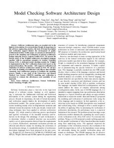
The topography step in the mask which allows this destructive interference is created by selectively etching into the mask substrate, which in turn requires a CAD data level to define the location of the desired phase region. Speaking from the point of view of the mask layout, there must be a PHASE1 shape on one side of each feature to be phase shifted and a PHASE2 shape on the other side. The PHASE1 shape would represent, for example, the portion of the mask which is transparent with 0° phase, and the PHASE2 shape the portion of the mask which is transparent with 180° phase. Although only one of these shapes may actually be manufactured as a recessed region in the mask, both shapes may need to be drawn in the layout for reasons which will become clear during the discussion of altPSM design rules which follows. Fig. 1 shows the relationship between the drawn layout shapes and the physical mask. Mask Layout PC PHASE2 PHASE1 shape shape shape cross section
Mask 180°
180° 0° chrome
0°
0° residual phase edge
Figure 1. Relationship between altPSM layout and mask. Many unique embodiments of the relatively simple altPSM design concept have evolved. The initial concept was introduced for alternating apertures in a dark background [1]; however, the same principle can be applied to imaging dark lines in clear backgrounds [2], as is needed in the lithography of the polysilicon conductor (“PC”), or gate level, of IC processes. Various techniques can be employed to print dark line patterns; [3]-[7] describe some of the approaches. While the techniques may differ, the fundamental design strategies and challenges remain relatively independent of the particular implementation chosen.
1.2
AltPSM Feasibility Assessment
Shortly after its conception in 1981, altPSM was used at IBM to print functional isolated device structures at extremely small dimensions (200 nm, using a low-NA 365 nm I-line exposure tool) [8], thus demonstrating the potential of altPSM for practical resolution enhancement. The development of automated design systems that could convert entire logic chip polysilicon conductor levels to altPSM layouts allowed full chip demonstrations of this powerful lithography technique in 1996 [9]. Approaching the 180 nm technology node in 1997, altPSM presented a possible lithography solution for the logic gate level and promised significant processing benefits. It was well known at the time that altPSM would present significant challenges to the design community, require tradeoffs in layout density, and necessitate changes to the established design flow. Thus, a detailed study was undertaken to quantify the net cost of implementing altPSM as the as the lithography process of record for an entire logic technology generation. This study included the development of altPSM design rules and design rule checking approaches and tools, further evolution of the altPSM design engine, and the creation of algorithms and tools for automated design migration using altPSM [10]. The study further involved the development of design methodologies for circuit types including full custom, synthesized, ASIC, array, and several mixtures thereof, the education of dozens circuit designers in the process of altPSM design, the conversion of several hundred layouts to altPSM designs, and front-up design for altPSM of three different full-scale test chips. This comprehensive look at the entire altPSM design process allowed us to evaluate the impact of altPSM in terms of layout density, designer productivity, and infrastructure required (both tools and methodologies). The full details of this study will be reported elsewhere [11]; here we concentrate on a single aspect of the altPSM design process: the challenge of applying standard design rule checking (DRC) approaches to altPSM designs. We describe a general rules-based approach to altPSM design, detail a few such design rules, and show how “legal” layouts can easily fail to produce altPSM solutions. We relate some of the difficulties in maintaining consonance between the altPSM design engine and the DRC tools, and finally present our conclusions as to the most realistic approach to dealing with these issues.
2. ALTPSM DESIGN APPROACH All other RET can be applied to the design data after “tape-out” of the design. The circuit designer does not even need to know that RET are being used. AltPSM is fundamentally different in that it requires designer intervention fairly early in the design process. As will be seen, altPSM design carries with it the potential for longrange shape interactions which can result in a failure to find a valid altPSM solution (that is, one where every feature to be phase shifted can have a 0° phase on one side and a 180° phase on the other). If these conflicts are not detected until the mask data is being generated, one must essentially choose between sending the data back to the designers for re-work, or simply not phase shifting those features (which could result in yield problems and later rework of the design anyway). Either choice may be expensive. Furthermore, if the circuit designers don’t understand altPSM, they may not be able to repair the problems when the design is rejected.
Thus, our fundamental altPSM design approach relies on knowledgeable circuit designers who both understand and implement the altPSM solution for their designs.
2.1
Rules-Based Approach
In a rules-based approach to altPSM design, a set of design rules are derived from the lithography system in use (i.e., λ, NA, partial coherence, etc.), the altPSM technique selected (e.g. trim mask, block mask, conjugate twin-shifter, etc., see [3]-[7]), and the desired minimum feature size and tolerance. These rules govern both the level to be phase shifted, and the design levels for the phase shapes themselves. This approach has the benefit of being predictable: a designer can hand-draw the phase shapes and arrive at exactly the same solution as a CAD tool following the same rules (with the possible exception of phase “color” assignment). A rules-based method is not the only way to approach altPSM design. One could use a simulation-based method which attempts to find lithographically optimized solutions for local layout configurations. Thus, the same basic PC layout construct may not always end up having surrounding phase regions which are identical in size and shape. A simulation-based method has an advantage over a rules-based approach in that it is more flexible; trade-offs can be made to the optimal lithographic result in return for not having to change or manipulate design data. However, there will eventually be limits in which the lithographic result is unacceptable, and the PC layout will have to be modified. While a simulation-based approach is valuable and may even be necessary for some of the highest density layouts, we do not feel that it is practical for full-scale chip design.
2.2
AltPSM Design Flow
In the basic rules-based altPSM design flow, the circuit designer first draws or generates a layout which contains shapes on the design level to be phase shifted (in this case, the PC level). The designer then runs a DRC tool which checks the conventional design rules (width, spacing, interaction with other levels) as well as some new types of design rules which are specific to altPSM design. The purpose of these checks is to give some degree of confidence that an altPSM solution will be possible. The designer next runs another tool which automatically creates and places the phase shapes into the layout. In our case, the phase generation tool is implemented using Niagara [12], an IBM-proprietary shape manipulation engine used extensively for physical IC design functions. These first two steps are repeated as necessary until a finalized design with a legal altPSM solution has been created. Hierarchical construction of the full chip design then proceeds (see [11] for discussion). A final DRC step which checks the phase shapes themselves as well as the PC level is undertaken to ensure that no modifications which would invalidate the altPSM solution were made after its initial generation.
2.3
Other Assumptions
In our approach to altPSM design, we assume that the phase shape generation tool is not allowed to manipulate the existing layout shapes in any way. The tool is only allowed to create and add phase shapes, or report a failure to find an altPSM solution. We also do not permit “critical edges” (an edge of a feature which is to be phase shifted) to be broken into multiple phase regions. Each critical edge can touch only one phase “color” for its entire length.
This is done to eliminate the negative lithographic impact of residual phase shadows.
critical features (width < PCc) must have a phase transition across the major axis, and
1.
non-critical features (width ≥ PCc) do not require a phase transition, where PCc is the width at which phase shifting is no longer beneficial or necessary. 2.
3. BASIC ALTPSM DESIGN RULES 3.1 The Concept of Critical Features The first and most fundamental altPSM design rule is that “every critical feature on the level to be phase shifted must have a phase transition across its major axis.” Critical features are those which, based on their nominal size and required linewidth control, must be phase shifted in order to achieve an acceptable process window. Since the benefits of phase shifting decrease with increasing feature size, at some large feature size phase shifting becomes unnecessary. The major axis of a feature is in the direction perpendicular to the edges which are at or below the critical feature size. It should be noted that most layout features are not simple rectangles which lend themselves easily to classification; rather, they are often polygons with segments at both critical and noncritical dimension. As seen in Fig. 2, identifying the critical features and determining the major axis can be complicated for compound shapes. In the face of such ambiguity, it is very challenging to implement algorithms for this deconstruction. Critical feature size. Features at or below this dimension must be phase shifted; larger features do not require phase shifting.
The phase regions themselves must have a set of traditional design rules governing their dimensions and spacing. The minimum width of a phase region, that is, the distance between a residual phase edge and the PC feature it is phase shifting, is driven by the required linewidth control for critical features as well as the focus asymmetry present in the lithography system. Residual phase edges on the mask also need to be at a minimum distance from one another to prevent the printing of residual images at process window extremes. Additionally, residual phase edges must be kept a minimum distance from chrome regions to prevent undue biasing of non-critical features. Fig. 3 shows design rules 3, 4, and 5: 3.
minimum space between an “interior” residual PHASE edge and PC, minimum space between PHASE shapes, and minimum space between an “exterior” residual PHASE edge and PC.
4. 5.
7 critical feature
1
major axis
6
3
non-critical feature
4 5
?? ? =
-or-
??
? =
-or2 Figure 3. Variables for the determination of altPSM design rules for phase shapes.
? =
-or??
? =
The remaining design rules for phase shapes are driven by mask manufacturability and inspectability requirements. Wherever phase regions abut or overlap, there must be some minimum allowable width of the resulting merged area. Additionally, there will be some phase-to-chrome overlay required by the mask process alignment tolerances. These are rules 6 and 7 of Fig. 3:
-or-
?? Figure 2. Definition of critical features and decomposition of compound shapes into critical and non-critical segments.
3.2
Design Rules Governing Phase Shapes
The development of a rules-based approach to altPSM design begins with the derivation of design rules governing the phase shapes which will be translated to etched regions on the mask. The first two rules address the fundamental concept of phase shifting critical features:
6. 7.
3.3
minimum width of a PHASE region, and PHASE-PC overlay.
Design Rules Governing the PC Level
Following the determination of the manufacturing design rules governing the phase shapes, the design rules governing the level to be phase shifted must be ascertained. These design rules can be directly inferred from the phase rules by drawing all possible combinations of interactions between shapes on the PC level. This is obviously a non-trivial task. Despite our efforts to capture all cases when enumerating our design rules, during the assessment of existing designs we continually found new constructs for which
the rules had to be modified or exceptions made. A more explicit description of a set of altPSM PC design rules is given in [11]. As will be seen, many of the altPSM rules for PC are non-traditional: rules concerning line-ends, parallel vs. perpendicular lines, opposing vs. non-opposing lines, adjacent vs. non-adjacent lines, etc. This complicates not only the understanding of these rules by designers, but also the checking of these rules by DRC tools. Fig. 4 shows how a design rule governing the phase shapes may affect the allowable relationships between PC shapes. Another interesting result of the interplay between the phase design rules and the PC shapes is that a phase design rule may constrain the space of altPSM solutions instead of constraining the relationship between PC shapes. Sample phase design rule: minimum space between two PHASE shapes. Motivation: to prevent printing of a shadow (in a conjugate twin-shifter method), or to leave adequate space for the trim mask (in a 0-180 approach). Implications of this phase design rule to PC design rules: Minimum space between PC line-end and perpendicular PC line. Implications of this phase design rule to altPSM solution space: If PC shapes are “too close” to allow for this spacing, a single phase region is created, resulting in two possible altPSM solutions instead of four.
key steps in the altPSM design process. For the PC level, traditional DRC approaches of checking line widths and spacings may not be sufficient. It is therefore worth considering whether the PC altPSM DRC can be dispensed with in favor of simply testing the layout for “altPSM compliance” - that is, whether or not a valid altPSM solution exists. One method for doing this is the checker proposed by Galan, et al. [13]. This method takes advantage of the fact that for logic polysilicon conductor levels, the goal of the phase shift design is to create a 180° phase transition coincident with the major axis of the critical patterns; i.e. the background of the layout needs to be manipulated in such a way that opposite sides of a critical feature see opposite phases. This simple principle allows the layout to be broken into three useful pieces with the following properties: 1.
phase transitions, which are linear constructs defined by the abutment of two regions of opposite phase. Phase transitions must be collinear with critical structures. 2. free space, which is any portion of the layout that can be traversed by a phase transition. Since phase transitions are not allowed to cross one another, any critical structure and the space occupied by its phase regions is not free space, and any space between critical regions that is occupied by a common phase region is not free space. However, open regions of the layout and, depending on details of the design methodology, non-critical structures, are free space, i.e. layout space that can be traversed by a phase transition. 3. nodes, which are simply the ends of the phase transitions. Checking the phase shiftability of an arbitrary layout is now simply reduced to the task of determining whether all phase transitions can be joined into closed polygons without crossing through forbidden space (i.e. not free space). Since the phase regions can only assume two values, this task is further reduced to verifying that any free space contains an even number of nodes. Any odd node in an isolated free space will not be able to connected into a closed polygon (Fig. 6).
Figure 4. A sample phase design rule and its implications to PC design rules and possible valid altPSM solutions.
3.4
Non-Phase-Shiftable Constructs
Even the most sophisticated altPSM phase design tool will fail to conflict convert any arbitrary layout to an altPSM design. Certain topologies, such as a three-way Figure 5. A three-way intersection intersection of critical (“T”) of lines at critical dimension cannot be phase shifted. dimension lines, cannot be converted to an altPSM design such that all three critical lines receive the required phase transition (see Fig. 5). There are also instances where multiple phase runs join at a single node, leading to the potential for long range phase conflicts. These types of “topological” design rules are difficult to describe as well as difficult to implement and verify.
4. DRC CHALLENGES Accurate and efficient design rule checking (DRC) of both the level to be phase shifted and the phase shapes themselves are two
transition axis forbidden space paired node odd node Figure 6. Free space method for verifying phase shiftability. The outer free space has 5 nodes, the inner one has 1. While it is possible to base phase shift design tools on the concept of connecting the nodes at the ends of phase transitions that are collinear with critical layout segments ([13], [14]), design rule checking based on this methodology has the distinct disadvantage that an accurate assessment of the free space requires most of the complexity involved in the actual phase shift design. Hence, another approach is to dispense with the DRC of the level to be phase shifted altogether, simply run the altPSM design tool to generate the phase shapes, and then DRC check the result. Preferably one would check with a different approach than the one which was used to create the phase shapes. Unfortunately, this
method does not really satisfy most design methodologies. In general, fast and accurate DRC approaches can be as complicated as the altPSM design itself, and this portion of the total altPSM design strategy is not to be dismissed lightly. A few of the more challenging aspects of altPSM DRC are discussed below.
4.1
Critical Features and PC DRC
Conventional intra-level PC design rules govern width and spacing of PC features. The concept of different rule values in different circumstances is not entirely new; e.g. there may be different allowable values for gate-gate (PC ∩ AA) space than for wirewire space. AltPSM design adds further complication in that space rule values may change as PC linewidth changes. Thus, the DRC tool must divide up the polygons into critical (“PCc”) and noncritical (“PCnc”) segments and apply the rules differently to PCc and PCnc. This greatly increases the complexity of checks on this level (see Fig. 7). Before altPSM: PC to PC space is fixed rule.
AltPSM rule may have different values for PCc to PCc, PCc to PCnc, or PCnc to PCnc space, even for different segments of the same polygon: critical PC (PCc)
non-critical PC (PCnc)
Line-ends, usually those edges which are at or below the critical dimension, are frequently featured in altPSM design rules. One such case is the “included line-end,” which occurs when a lineend falls into the projection of the major axes of its two nearest neighbors (Fig. 8). A free space must be created between the two outer lines, and the PCc-PCc space rule takes on yet another value.
Figure 8. For an “included line-end”, the spacing between the outer PC features is relevant. Another example is PCc line-end to PCc line-end spacing. This rule is dictated by PHASE to PHASE spacing (Fig. 9). However, when the PC polygons are sorted into critical and non-critical features, additional line-ends appear. The line-end spacing rule must be applied here as well, effectively limiting the size of a noncritical block which breaks a critical PC line. This example further emphasizes the need for agreement between the phase generation tool and the DRC tool. If the DRC tool decides that this polygon is composed of two critical lines with a non-critical segment between them, it will expect two phase transitions and a minimum space between opposing line-ends. If, on the other hand, the phase generation tool determines that the non-critical segment is too small to act as a phase-breaking block, it may categorize the entire polygon as critical and generate only one phase transition.
⇒
⇒
Figure 7. The PC design rules or design rule values may be different for critical and non-critical PC. It is extremely important to maintain agreement between the DRC tool and the phase generation tool in the definition of critical features. After the phase shapes have been generated, the DRC tool will be checking to see that each critical feature has a PHASE1 shape on one side and a PHASE2 shape on the other side for the full length of the critical edge. If the definitions do not match exactly, DRC errors will be generated or real errors missed.
4.2
Line-Ends and Free Space
A second complexity of altPSM PC DRC is the need to further classify the different edges of shapes and determine their orientation w.r.t. one another. Whether their major axes are ⊥ or // to each other can change the spacing rule for two or more PC lines.
⇒
-or-
⇒
Figure 9. The rule regarding spacing between ends of critical lines becomes less obvious when the line-ends are joined by a non-critical segment.
4.3
Non-Contingent and Missed DRC Errors
Another frequent consequence of altPSM PC DRC is the detection of errors whose best remedy is actually different from a simple correction of the particular errors noted. For example, a “beltbuckle” configuration of critical PC lines (Fig. 10) yields a phase transition error as well as two PCc-PCc line-end errors. Simply repairing those errors to meet the design rule values does not necessarily produce the optimal altPSM design solution. A designer with experience quickly learns that he can repair the error without substantially growing the design by converting some of the PC to non-critical dimension and changing the spacing rule rather than obeying the current rule. In our experience, solutions of this type almost invariably satisfy the needs of the design better
than the simple spacing correction and do so without requiring additional area. This is an example of the type of designer intervention which is key to the success of altPSM design and which cannot be substituted in a data-prep operation. A design with an altPSM conflict and DRC errors denoting bad PC-PC spacings:
The design modified to simply correct the DRC errors per the design rules:
An alternative correction which satisfies different design rules from the ones flagged, and almost invariably satisfies the needs of the design. Figure 10. Simple corrections of DRC errors do not necessarily yield the optimal altPSM design solution. Finally, with any reasonable set of design rules, there can exist PC DRC correct layouts which still fail to produce a valid altPSM solution. The most phase conflict common of these is the “odd-even run” pictured in Fig. 11. The method of counting nodes in free Figure 11. The “odd-even run” - a space would find this layout which passes PC DRC but fails to yield a valid altPSM solution. problem; conventional DRC does not. As before, the bulk of the work of finding the altPSM solution needs to be done to locate this error, calling into question the purpose of a pre-phase-generation DRC check.
5. CONCLUSIONS The fact that altPSM requires specific design constraints, not all of which are readily checkable with conventional DRC tools, means that altPSM cannot be applied as part of mask data preparation without careful integration of altPSM into the entire chip layout design process. Only an extremely conservative set of design rules (basically, minimum PC-PC space everywhere is twice the minimum width of a phase region plus the minimum phase-tophase spacing) can guarantee phase shiftability. The consequences to layout density of this set of rules are nothing short of disastrous. However, with a fairly comprehensive set of rules and good designer education regarding altPSM design practice, the vast majority of designs which pass DRC of the altPSM PC design
rules will also yield successful generation of valid phase shapes. It is crucial, however, that consistency is maintained between the DRC tool and the altPSM generation method used. In our experience, this is the most challenging aspect of altPSM design. The DRC of the PC level is linked to the same “critical vs. noncritical” concept as the generation of phase shapes. Exact agreement is required between what the DRC tool calls “critical” and what actually ends up getting phase shifted. Furthermore, the cause-effect relationship in altPSM DRC is much more complicated than in conventional DRC in many cases. The point at which an error gets flagged (usually a gate with the same phase on both sides) is frequently not actually the cause of the problem due to the long range interactions of phase shapes. To facilitate layout legalization, a DRC tool which suggests layout fixes in addition to simply flagging errors will be extremely helpful (see [10]). In general, more sophisticated altPSM design approaches drive more sophisticated checking approaches to a point where “checkability” of the design becomes the gating factor.
6. REFERENCES [1]
M. Levenson, N. Viswanathan, and R. Simpson, “Improving resolution in photolithography with a phase-shifting mask,” IEEE Transactions on Electron Devices, V. 29, pp. 1828-1836, Dec. 1982.
[2]
M. Levenson, “Phase-shifting mask strategies: isolated dark lines,” Microlithography World, pp. 6-12, Mar./Apr. 1992.
[3]
P. Agnello, T. Newman, E. Crabbe, S. Subbanna, E. Ganin, L. Liebmann, J. Comfort, D. Sunderland, “Phase edge lithography for sub-0.1 um electrical channel length in a 200 mm full CMOS process,” VLSI Symposium, p. 79, 1995.
[4]
L. Liebmann, S. Mansfield, A. Wong, J. Smolinski, S. Peng, K. Kimmel, M. Rudzinski, J. Wiley, and L. Zurbrick, “High-resolution ultraviolet defect inspection of DAP (darkfield alternate phase) reticles,” in 19th Annual BACUS Symposium on Photomask Technology, F. Abboud, B. Grenon, eds., SPIE V. 3873, p. 148, 1999.
[5]
H. Ohtsuka, et al., “Conjugate twin-shifter for new phase shift method to high resolution lithography,” in Proc. SPIE, V. 1463, p. 112, 1991.
[6]
S. Kim, S. Woo, W. Han, Y. Koh, M. Lee, “Application of alternating phase shift mask to device fabrication,” in Proc. SPIE, V. 2440, 1995.
[7]
L. Liebmann and A. Wong, “Optimized alternating phase shift mask design,” filed as US patent docket FIS920000006US1, May 2000.
[8]
T. Brunner, et al., “170 nm gates fabricated by phase shift mask and top anti-reflector process,” in Proc. SPIE, Vol. 1927, p. 16, 1993.
[9]
L. Liebmann, I. Graur, W. Leipold, J. Oberschmidt, D. O'Grady, D. Rigaill, “Alternating phase shifted mask for logic gate levels, design and mask manufacturing,” in Proc. SPIE, V. 3679, p. 27, 1999.
[10] F.-L. Heng, L. Liebmann, and J. Lund, “Application of automatic design migration to alternating phase shifted mask design,” ISPD, Apr. 2001. [11] L. Liebmann, J. Lund, F.-L. Heng, and I. Graur, “Enabling alternating phase shifted mask designs for a full logic gate level,” to be submitted to IEEE Transactions on CAD. [12] P. Russell and G. Weinert, “System and method for verifying a hierarchical circuit design,” US patent #5528508, June 1996. [13] G. Galan, I. Graur, and L. Liebmann, “Phase shifted design verification routine,” US patent #5923566, July 1999. [14] T. Waas, et al., “Automatic generation of phase shift mask layouts,” Microelectronic Engineering, Vol. 23, pp. 139-142, 1994.