Figure 1: The equations, circuit diagram and symbolic representation of a ... ow charts and examples are shown in section 3. In section 4 .... Read the desired method of design, i.e. 1- TSC. 2- SFS/SCD. ... implicants and calculate the number of.
Design automation of self checking circuits S. M. Kia, S. Parameswaran Department of Electrical and Computer Engineering University of Queensland St. Lucia, Queensland, 4072, Australia
Abstract
In this paper we explain the steps of the CAD tools developed for self checking circuits. The CAD tools developed are used to design Strongly Fault Secure, Strongly Code Disjoint (SFS/SCD) and Totally Self Checking, Code Disjoint (TSC/CD) circuits. Self checking combinatorial and sequential synchronous circuits including shift registers, counters, adders and checkers are designed, using these tools. The output of these CAD tools is given in structural level VHDL which can be synthesized via commercial tools. Key words: Design Automation, CAD, Totally Self Checking Circuits, Strongly Fault Secure Circuits, VHDL.
1 Introduction
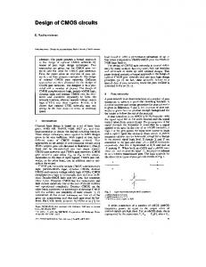
Self checking circuits give an indication before producing any error on the output. Two circuits which are currently used for self checking circuits are Totally Self Checking (TSC) [1] and Strongly Fault Secure (SFS) [2] circuits. TSC circuits give the indication of error after the rst fault occurrence. The SFS circuits may not give an indication of error after the rst occurrence of a fault. But, the SFS circuits continues to operate correctly until a certain number of faults, before giving an indication of error. For cascading the self checking circuits at system level, the error propagation or Code Disjoint (CD) [1] property is quite important. There is no guarantee that TSC circuits are CD and thus may have to use checkers between succeeding circuits. Due to the di�culty in making TSC circuits CD, a method for making SFS combinational circuits Strongly Code Disjoint (SCD) [3] has been developed in [4]. The SCD property ensures the error propagation in the SFS circuits. They have been further extended in order to create asynchronous circuits [5]. These TSC and SFS methods have been applied for combinational parts of synchronous circuits. The authors have introduced two low cost ip ops (DDn FF and TTn FF ) which are TSC and CD. These FFs use two rail codes which is suitable for TSC/CD and SFS/SCD synchronous circuits. Internal next state equations, output equations, circuit diagram and symbolic representation of DDn FF and TTn FF are shown in Figure 1 and Figure 2. The related methods of application and design of DDn FF and TTn FF are given in [6] and [7].
PRn CLR
O
Xn
Q
D O
O
O
O
O
C
O
Cn O
O
Dn
O
PR O
O
Qn
O
O
X
CLRn
Internal next state equations: X = Cn . Dn + C . X Xn = Cn . D + C . Xn Output equations: Q = C . Xn + Cn . Q Qn = C . X + Cn . Qn
PR
PRn
O
C Cn
O
Q
D F.F. Dn
Qn
O
CLR
CLRn
Figure 1: The equations, circuit diagram and symbolic representation of a DDn FF When a whole self checking system is implemented using self checking modules (combinational logic and synchronous circuits, adders, registers etc), the level of complexity increases. Thus it is critical to be able to analyze and simulate such circuits before manufacturing. The ability to explore the design alternatives is an added necessity in a self checking design environment. In this paper the authors introduce the algorithms of CAD tools which can design the modules of TSC, SFS/SCD and TSC/CD combinational and sequential circuits and checkers needed for self checking designs. These modules are then manually put together to build the total system. The outputs are presented in structural VHDL. The design procedure is explained in section 2. The
ow charts and examples are shown in section 3. In section 4 conclusions are given.
2 Self checking processor design
The design procedure of the self checking processors with our CAD tool is done in the following order.
Permission to copy without fee all or part of this material is granted provided that the copies are not made or distributed for direct commercial advantage, the ACM copyright notice and the title of the publication and its date appear, and notice is given that copying is by permission of the Association for Computing Machinery. To copy otherwise, or to republish, requires a fee and/or speci c permission. (c) 1994 ACM 0-89791-687-5/94/0009 3.50
PRn
Process description O
CLR
Subsystems and ~~~ their interconnections
O
T
Xn
Q
O O
O
TSC/CD flipflop in VHDL
O
O
C
~~~ ~~~
O
FF
Design detail information of each cicuit
000 010
11 01
110
10
Gate struture in VHDL
Cn O
O O
O
O
CAD tools developed in house
O
Tn
Qn
X O
PR
Optimum TSC/CD modules in VHDL
O
e.g. I.Adder II.Shift register III Counter IX.Two rail checker ...... ......
CLRn
Internal next state equations: X = Tn . Qn + Cn . T . Q + C . X Xn = Tn . Q + Cn . T . Qn + C . Xn
PR
O
Output equations: Q = C . Xn + Cn . Q Qn = C . X + Cn . Qn
Q F.F.
Cn O
Tn CLR
O
SFS/SCD sequential circuits in VHDL e.g. Controllers
PR
T
C
SFS/SCD combinational circuits in VHDL e.g. ROMs
SFS/SCD verification of the total system
Qn CLRn
Figure 2: The equations, circuit diagram and symbolic representation of a TTn FF Figure 3 depicts the procedure. 1. The introduction of basic elements (e.g. logic gates) and components (e.g. TSC/CD FlipFlops). 2. The construction of commonly used circuits are held in a library of modules. For example, adders, counters, shift registers and two rail checkers are built in this stage. As far as possible these circuits are TSC/CD in order to have low design cost. We have a single bit designed of these (prede ned) circuits in the library. 3. The analysis and generation of the combinational circuits for di�erent input-output mappings. These circuits are designed with SFS/SCD or TSC/CD rules and can be used with di�erent unordered codes1 . 4. The analysis and generation of the sequential circuits for controllers. These modules are clocked and they are SFS/SCD or TSC/CD utilizing the two rail code for state assignments. 5. The construction of the whole system with the generated parts. The subsystems previously designed are connected together manually, in order to arrive at the nal design. 1 Unordered codes are used for self checking circuits. Two rail and Berger coding can be done by the CAD tools. Other kinds of unordered code such as m out of n codes can be given too.
Synopsys CAD tools
Final Design
Figure 3: Procedure of automated self checking system design with VHDL structure Presently the CAD tools developed in this project nd the equations and create separate VHDL descriptions for each module. The input to the CAD tools di�er according to the circuit. The output of the CAD tools are modules such as combinational logic, synchronous sequential logic, adders, registers, etc, written in VHDL structural description. These descriptions are put together to create a total VHDL description of a system which is then put through commercial design tools to create the nal system.
3 Algorithms of developed CAD tools
In the system developed at the University of Queensland, two analytical CAD tools generate combinational and synchronous sequential logic circuits. The combinational circuits can be made with variety of unordered codes. The unordered codes that are used for self checking circuit design, generate the SFS circuits [2]. The method in [5] is used to generate TSC circuits. The transformation of an SFS circuit to an SFS/SCD is based upon the method in [4]. By applying the method of [5] on SFS/SCD circuits, the TSC/CD combinational circuits are built. Prede ned component generators are also available which create TSC/CD adders, decoders and checkers. These prede ned component generators generate circuits for any bit widths prescribed by the user. Non prede ned
combinational circuits are created in two level logic format (either And{Or format or Nand format). The synthesis of these circuits will be given in Algorithm 1. The synchronous circuits use two rail codes. Synchronous circuits are divided into two sections: the rst, prede ned circuits such as shift registers, counters etc; and the second controllers. In the rst category, a simple generator generates optimized TSC/CD circuits given the necessary bit width. In the case of the controller, a more elaborate algorithm is used to design the circuit. The controller algorithm will be given in \Algorithm 2". Self checking Controllers have a state register which is constructed with DDn FF s or TTn FF s, and self checking combinational circuitry. The models for TSC/CD and SFS/SCD synchronous circuits are presented by the author in [8]. Details of the self checking system design are given by the author in [9]. The steps of transaction with these two CAD tools are summarized in the following two sections. The terms used in the following sections are due to mentioned design methods.
3.1 Combinational logic circuits Algorithm 1
1. Read the input output table. 2. Read the number of input output bits from the input output table. 3. Read the desired method of coding for inputs and outputs, i.e. 1- Two rail code 2- Berger code 3As it is 2. 4. Create a new input output table with desired coding and nd the number of bits for input output coding. 5. Read the desired method of design, i.e. 1- TSC 2- SFS/SCD. 6. Separate the implicants for each output variable. 7. According to the selected option follow the TSC(a) or SFS(b) methods. (a) TSC procedure: i. Extract the testing implicants for each variable. ii. Check every variable in every implicant for each function to be tested by testing implicants. If any variable is not tested, eliminate that variable. Continue this process for all variables of the functions which are left over from last elimination. iii. Simplify the repeated implicants and implicants which are subset of bigger implicants and calculate the number of product terms and size of each product term.
2 Any other kind of unordered code like m out of n is directly given in the input table and no more coding is required.
(b) SFS/SCD procedure: i. Follow the covering-nc-CD procedure: Find every immediately covering non codeword which covers at least two codewords. If outputs of all covered codewords are the same, make them different by setting new values to don't care conditions and if there is no don't care value, add new two rail codes. ii. Follow the covered-nc-CD procedure: Find every immediately covered non codeword which is covered by at least two codewords. If outputs of all covering codewords are the same, make them di�erent by setting new values to don't care conditions and if there is no don't care value, add new two rail codes. iii. Set any left don't care values to a two rail code, e.g. 01 or 10. iv. Calculate the number of product terms and the size of each product term. 8. Print the output functions if required. 9. If TSC/CD was selected, use the SFS/SCD design and apply the TSC method else go to the next step. 10. Write the VHDL description of circuit structure as follows. (a) Read the name of the le for VHDL description of the circuit. (b) Read the desired hardware i.e. 1- AND-OR 2-NAND. (c) Put the entity information in the le. (d) Put the necessary component in the le. (e) Introduce the interconnection points as signals in the le. (f) Make a NAND or AND gate for every new product term (do not repeat). (g) Make a NAND or OR gate for every output function. (h) Make the input, output and intermediate line connections. (i) Print the ending message including number of gates and the sum of their fan-in. Any non meaningful input will result in an error message being displayed.
3.1.1 Combinational circuit design example
Given below is the input to Algorithm 1. The rst line gives the program information about the number of inputs and outputs. In this case there are three inputs and four outputs.
34 000 0011 001 0110 010 1100 011 1001 100 1010 101 0101 110 0011 111 1010 We select the Berger coding for the input which adds two more bits to the input codes. The 2-out-of-4 coding is chosen for the output of the circuit as shown in the above input-output table. The SFS/SCD functions of outputs (Z) are found due to inputs (a) with no added extra output lines as follows: Z1 = a2a4 + a2a3a5 + a1a4 + a1a2a3 Z2 = a3a4 + a2a4 + a1a3a5 Z3 = a4a5 + a3a4 + a1a4 + a1a2a5 + a1a2a3 Z4 = a4a5 + a2a3a5 + a1a3a5 + a1a2a5 Then by demanding the TSC/CD functions the equations program generates the following: Z1 = a2a4 + a2a3 + a1a4 Z2 = a3a4 + a2a4 + a1a3a5 Z3 = a4a5 + a3a4 + a1a4 + a1a2 Z4 = a5 The procedure is continued and the VHDL description of the circuit is given with the size information (10 gates which the sum of their fan-in is equal to 25) of the circuit. Shared terms have been taken into account.
3.2 Synchronous circuits
Some extra points related to sequential synchronous design are considered below. � Both functions of internal states and outputs of the circuit must be considered. � Only two rail codes are used. � The internal states or outputs functions can be TSC, SFS, TSC/CD or SFS/SCD. � With two rail codes, the covering and covered ncCD procedures in SFS/SCD design are identical. � The Mealy and Moore model can be selected. � One of two Flip-Flop kinds (DDn FF or TTn FF ) can be selected for a state register. � The product terms of the combinational logic are shared between internal states and outputs. The algorithm is as follows:
Algorithm 2
1. Read the synchronous circuit table.
2. Read the desired kind of Flip-Flop for state register, i.e. 1-DDn FF 2-TTn FF 3. Read the number of bits and combinations of input, state and next states from the synchronous circuit table. 4. If TTn FF is selected, change the next state table accordingly. 5. Read the desired method of design, i.e. 1- TSC 2- SFS/SCD. 6. Read the desired model of the synchronous circuit, i.e. 1- Mealy 2- Moore. 7. For Moore model read if the output is to be extended as a Mealy model or not. 8. If Moore model output is to be extended as a Mealy model, put equal outputs in the table for all input assignments. From this point the extended Moore to Mealy model will be considered as a Mealy model. 9. Separate the implicants for each next state variable. 10. According to the selected method follow the TSC (a) or SFS/SCD (b) methods for the next state table. (a) TSC procedure for next state table: Follow the TSC procedure for the next state functions as the TSC procedure for outputs of the combinational circuit (step \a" in the combinational circuit algorithm). (b) SFS/SCD procedure for next state table: Follow (i) for Mealy and (ii) for Moore model. i. Do not change the next state table. It is already SFS. ii. Follow the SFS/SCD procedure for the next state functions as the SFS/SCD procedure for outputs of the combinational circuit (step \b" in the combinational circuit algorithm). 11. Print the next state functions with new added functions if wanted. 12. For Mealy model implicants will be made according to input and state assignments. For Moore model, implicants will be made only according to state assignments. 13. Separate the implicants for each output variable. 14. According to the selected method follow the TSC (a) or SFS/SCD (b) methods to derive the output table.
15. 16. 17. 18.
(a) TSC procedure for output table: Follow the TSC procedure for the output functions as the TSC procedure for outputs of the combinational circuit (step \a" in the combinational circuit algorithm). (b) SFS/SCD procedure for output table: Follow the SFS/SCD procedure for the output functions as the SFS/SCD procedure for outputs of the combinational circuit (step \b" in the combinational circuit algorithm). Print the output functions with new added output functions if required. If TSC/CD was selected, use the SFS/SCD design and apply the TSC method else go to the next step. Write the VHDL description of circuit structure (see step 10 of the combinational circuit algorithm). Display the ending message including the number of gates and the sum of their fan-in and the number of Flip-Flops.
3.2.1 Synchronous circuit design example
Suppose the input le name for our synchronous circuit design is `SYNexample' with the following inputoutput coding relations. 8656 010101 010110 011010 011001 101001 101010 100110 100101 010101 010110 101001 101010 011010 11112222 22333322 44444444 55444455 22222222 Mealy 4 0101 0101 0101 0101 0101 0101 0101 0101 0101 0110 0110 0101 0101 0110 0110 0101 1001 1001 1001 1001 1001 1001 1001 1001 0101 0101 0101 0101 0101 0101 0101 0101 1001 1001 1001 1001 1001 1001 1001 1001 The rst line shows that there are 8 input combinations using 6 input variables and 5 state assignment combinations using 6 state variables. The next two lines give the input assignments and state assignments. The next states are given by their numbers in the next ve lines. For example, the second line of these ve lines is 22333322 which gives the eight possible next states under eight possible input combinations if the present state is 2. The controller is a Mealy model with 4 output variables. The output table is given in the last 5 lines. Note that two rail codes are used.
The SFS/SCD design of the controller with DDn FF s (TTn FF s is also possible) is made by adding a
pair of lines to the output lines. The TSC/CD process simpli es the SFS/SCD equations [5]. The TSC/CD next state (Y ), output (Z ) and added output (ZA ) equations found by the developed CAD tools are given below: Y1 = y4y5x3 + y3y6 + y1x3 Y2 = y4x4 + y4y6 + y5x4 + y2y3 Y3 = y4y5x3 + y3y6 + y1 Y4 = y4x4 + y4y6 + y2x4 + y2y3 Y5 = y6x1 + x1x4 + y5x4 + y3 Y6 = y4y6x2 + y4x2x3 + y4y5x3 Z1 = y3y6 + y2y3 + y1y6 + y1y4 Z2 = y2y4 + y1y3y5 Z3 = y2y4y5x5 + y2y3y6 + y1y4y6 Z4 = y2y4x6 + y2y4y6 + y5x6 + y1y3 + y3y5 + y1y5 ZA1 = y6x2x4x5 + y6x2x3x6 + y6x1x3x5 + y6x1x4x6 + y2y4y5x2x4x6 + y2y4y5x2x3x5 + y2y4y5x1x3x6 + y2y4y5x1x4x5 + y3x2x4x5 + y3x2x3x6 + y3x1x3x5 + y3x1x4x6 +y1 x2x4x5+y1 x2x3x6+y1 x1x3x5+y1 x1x4x6 ZA2 = y6x2x4x6 + y6x2x3x5 + y6x1x3x6 + y6x1x4x5 + y2y4y5x2x4x5 + y2y4y5x2x3x6 + y2y4y5x1x3x5 + y2y4y5x1x4x6 + y3x2x4x6 + y3x2x3x5 + y3x1x3x6 + y3x1x4x5 +y1 x2x4x6+y1 x2x3x5+y1 x1x3x6+y1 x1x4x5 By following the CAD steps, the circuit design in the VHDL description language is made with 3 DDn FF s, 69 gates which the sum of their fan-in is equal to 272. The block diagram of the TSC/CD controller is shown in Figure 4. The SFS/SCD implementation has the same structure as in Figure 4 except for a larger combinational part. Other controller structures can be implemented. The ZA1 and ZA2 output lines support the error propagation of the controller. These two lines can be used for the cascading of self checking circuits by combining them to the same lines of previous stages.
3.2.2 A Large controller design example
As an example of a large circuit, the self checking structure of the controller of a 32 bit sample processor, DP32 given in [10], is designed. The next state diagram is derived with 22 states. The inputs are decoded to get 7 input two rail code pairs. Five pairs of two rail codes are used for state assignments. The outputs are decoded to 24 pairs of two rail codes. The next state and output table of the controller has 128 columns and 22 rows. For the TSC/CD design of the circuit as a Mealy model, the circuit required about 3100 gates and 5 self checking Flip-Flops as state registers. After including the next state and output table information in a le, the total time including the latency for choosing different design options is less than one hour (45 minutes user time, 30 seconds system time) on a DEC 5000 series computer. Note that the circuit is rst designed as SFS/SCD and then changed to TSC/CD. It is easy to examine di�erent state assignments and models to
ZA1 ZA2
O.L.
Z1 Z2
SFS/SCD
Z5
(TSC/CD) (sum level)
Z6
X1
X2
X5 X6
First logic level of product terms
I.L.
Y1
SFS Y2 (TSC) (sum level)
Y5 Y6
combinational logic
DDn-FF or TTn-FF
DDn-FF or TTn-FF
register
Figure 4: Block circuit diagram of TSC/CD (SFS/SCD) controller 'SYNexample' get to an optimum design. The complexity of the SFS/SCD design procedure increases exponentially with the number of inputs and outputs [4]. This exponential complexity favours the decomposing of circuits into smaller sections.
4 Conclusions
Self checking circuit CAD tools were introduced. Two algorithms were given which designed combinational circuits and synchronous controllers. Other generators are used for prede ned components such as shift registers adders etc. Applications of the two algorithms were demonstrated through examples. The hard and time consuming design task of self checking circuits are accurately done in a short time. It is now possible to explore the design space to nd an optimum solution. The designed circuit output is also given in VHDL which can then be synthesized using commercial tools.
References
[1] D. A. ANDERSON & G. METZE, \Design of totally self checking check circuits for m-out- of-n codes ," IEEE Transactions on Computers C-22 (Mar. 1973), 263{269. [2] J. E. SMITH & G. METZE, \Strongly Fault Secure logic networks ," IEEE Transactions on Computers C-27 (June 1978 ), 491{499. [3] M. NICOLAIDIS, I. JANSCH & B. COURTOIS, \Strongly code disjoint checkers," Proc. of 14th Fault Tolerant Computing SymposiumFTCS-14 (1984), 16{21.
[4] S. PAGEY, S. D. SHERLEKAR & G. VENKATESH, \A method for the design of SFS/SCD circuits for a class of unordered codes ," Journal of Electronic testing: Theory and Applications 2 (1991), 261{277 . [5] M. DIAZ, P. AZEMA & J. M. AYACHE, \Uni ed design of Self-Checking and Fail-Safe combinational circuits and sequential machines ," IEEE Transactions on Computers C-28 (Mar. 1979 ), 276{281. [6] S. M. KIA & S. PARAMESWARAN, \Design of TSC and SFS/SCD synchronous circuits with TSC/error propagating Flip-Flops," in Proc. 12th Australian Microelectronics Conference, H. B. HARRISON, ed. #MICRO'93, IREE,I E Aust, Marriott Surfers Paradise Resort, Queensland, Australia, Oct. 1993, 75{80. [7] S. M. KIA & S. PARAMESWARAN, \Synchronous TSC/CD error indicator for self checking systems," in The 1993 Paci c Rim International Symposium on Fault Tolerant Systems, T. S. DILLON & K. E. FORWARD, eds. #PRFTS'93, IEEE, CRL Publishing Ltd, London, Melbourne University, Melbourne, Australia, Dec. 1993, 156{ 160. [8] S. M. KIA & S. PARAMESWARAN, \Novel architectures for TSC/CD and SFS/SCD synchronous controllers," in 12th IEEE VLSI TEST SYMPOSIUM, Y. ZORIAN, ed. #VTS94, IEEE, Cherry Hill, New Jersey, April 1994, 138{143. [9] S. M. KIA, \Novel circuits, methods and automation in self checking circuits," Department of Electrical and Computer Engineering, the University of Queensland , PhD thesis(to be submitted) , Australia, 1994. [10] P. J. ASHENDEN, The VHDL Cookbook, Internet, Dept.of Computer Science, University of Adelaide, South Australia, 1990.