DESIGN SENSITIVITY FOR SKIN EFFECT AND MINIMUM VOLUME OPTIMIZATION ... shielding effect is determined by the flow patterns of the induced.
I
IEEE TRANSACTIONS ON MAGNETICS, VOL. 28, NO. 5, SEPTEMBER 1992
2817
DESIGN SENSITIVITY FOR SKIN EFFECT AND MINIMUM VOLUME OPTIMIZATION OF GROUNDED AND UNGROUNDED SHIELDS
K. Weeberl, E. Johnson2, S. Sinniah2, K. Hob3, J.C. Sabonnadiere4, S.RH. Hoolez
-
Abrtruct "be .Im of this paper is twofold: (a) to extend the ddgn sensitivity d y s l s of finite element eddy current formulatiom
to t k situation of constrdnlng the total induced current by applying Ampere's law and @) to present a formulation for the minimum uelght optimization of magnetic shields. In the first step an existing flnlte element formulation is implemented and validated with test measurrments In the second step design sensitivity analysis is derived for this formulation. The formulation of the optimal design of a shield b based on these sensitivity calculations and solved by nonlinear programming methodologies. The presented formulation results in a large number of expliclt and nonlinear constraints, which require the utlllzatlon of appropriate nonlinear programming methods. The presented optimization examples demonstrate that grounded shields are far more eiIeetlve than ungrounded ones.
L FINITE ELEMENT FORMULATION AND EXPERIMENTAL VERIFICATION
,
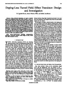
coefficients of all the elements connected to this one node. The column vector {J} represents the current distribution of the field excitation at some distant point from the shield. The solution of equ. (1) for the magnetic vector potential A enables one to determine the magnetic field distribution in the solution domain as well as the induced current densities in the shield. The analysis of a grounded shield is performed by neglecting the term [Q][C]of the imaginary part, which is included for the analysis of ungrounded shields. Before proceeding to the task of determining optimal shield dimensions by numerical methods, the integro-differential formulation of equ. (1) was verified by comparison with experimental data. An ungrounded copper shield (a = 58.Oe6 Wm, thickness = 0.794 mm, width = 762 mm) was exposed to magnetic fields generated by a current of 8.0 A in a thin wire at a distance of 12.8 mm below the centerline of the shield. The magnetic filds were measured at a distance of 25.4 mm above the shield. The results obtained by the finite element analysis including the integral constraint for the induced current in the shield and the measurement data show satisfactory agreement(Fig. 1).
The effectiveness of magnetic shields for dynamic fields is based 011 W e e r e n t phenomena: highly permeable shielding materials rllrrct the magnetic fElds and thus prevent their further propagation. Mditionally, dynamic fsld variationsinduce currents in a conductive rbield which also contribute to the shielding effect. It is this confributionof induced currents that is investigated in this study. In the analysis of passive electromagneticshields for dynamic fields the shielding effect is determined by the flow patterns of the induced O~S eddy currents, which in turn depend on the grounding C O M ~ C ~ ~ of the shield. In the case of a grounded shield, the induced currents may flow in a closed loop through the shield and grounding conductor, resulting in a net current through the shield. On the other hand, if the shield is not grounded, no such closed current path exists and the induced currents have to close within the shield itself, resulting in a rmo Wal current flow through the shield. In terms of numerical anal*. this physical situation is realized by applying Ampere's law Witb 8 total current of zero around the shield or, equivalently, x ["I blcgrUing the induced current density in the shield cross section to aao.A finiteelement formulation of this additional integral constraint Fig. 1) Comparison of field values of measurements and numerical analysis above the ungrounded shield on the induced eddy currents has been presented by Konrad [1,2] and Mayergoyz [3]. Mayergoyz's method has the advantageof yielding a sparse matrix for solution. But we have chosen Konrad's approach, 11. MINIMUM VOLUME FORMULATION OF SHIELD because of its simplicity in boundary conditions and the use of the OPTIMIZATION same variable inside and outside conductors. The corresponding Shape optimization of grounded magnetic shields without the fdte element equation for 2-dimensional steady state problems is constraint of zero total current has been previously investigated by the givenas authors [4]. In those analyses the optimizationwas formulated based on a least square object function, which described the deviation of the (1). [[PI +MQI- jw$ll[Cl]. {A) = {J) flux density from a desired value in the shielded region. Thus the desired flux density value at sampling points along the boundary of The real part of the complex coefficient matrix is given by the the shielded region was exactly achieved at the optimal shield K e a b i h t y matrix p].The imaginary part consists of two terms: the one determines the currents induced in conductive materials as cofliguration. However, a more realistic formulation asks for the shield of minimum volume, which results in flux densities smaller than a given threshold value Bmin. In this case a desired shielding effect is achieved by a shield of minimum volume and therefore minimal material costs. For the formulationin terms of mathematical optimization methods, the parameter vector p contains n parameter values for the shield dimensions and the shield volume Vol is minimized as the objective function. The desired fsld values B d in the shielded region are imposed as inequality constraints to yield the -following minimum volume formulation of the shield design problem: I of Engineering.Harvey Mudd college,enrolled in a Qctorate's pogamattbeLaboratoired' 'que, ENSIEG. minimize F(p) = Vol(p) (2a) 2 m t of Engineerhrg,-=coelge, claremont, CA 91711, j = 1 ... m (2b) subject to gj(p) = Bj(p) - B,h 5 0 U.S.A. 3 ~osram ~anager,soutbem califomia=on ~ e s e a r center, ~h 6090 windale i = 1 ...n
-
Ave., Irvindalc.CA 91702, U.S.A. ENSIEG,38402 St. Martin #Heres, France.
4 L&xatoii d'Elec"ique,
reQivedFebruary 17, 1992. This work has been supported by the y Mudd College - Southem California Edison Center of Excellence in
kIrm&pt
J&
m
Ebctricalsm.
In this formulation the nonlinear object function F(p) depends explicitly on the n design parameters pi. The parameter side ear and explicit in the n design parameters pi. The m constraintsare h constraintsfor the field values in the shielded region however depend
0018-9464/92$03.00 0 1992 IEEE
>, , 2818
implicitly and generally nonlinearly on the parameter vector p, which causes this opthiition problem to be a nonlinear one. Thus, suitable optimization techniques have to be applied to solve equ. (2) which is charactenzedby a significant number of nonlinear constraints. For the present study sequential quadratic programming (SQP) methods are selected which are regarded as the most efficient nonlinear programming algorithms today [5,6,7] and which handle large numbers of nonlinear constraints efficiently. Among the total number of constraints m only a subser is active at the optimum. This subset of indica j is contained in the active set A, which may contain ma 5 n constraints for the optimization problem not to be overdetermined. Equ. (2b) is satisfied as a strict equality for this subset of inequality constraints. At the optimum the Langrangian function relam the object function and the active constraints with the Lagrange multipliersX as
Lo = F@) +
x
gj(P) Xj
jc A
nonlinear constraints. The solution of the algebraic subproblem (6) for the search direction requiresrelatively small computationaleffort once the gradient information of the matrim A and W is available. IIL DESIGN SENSITIVITY ANALYSIS The gradient information of object and constraint functions is obtained by sensitivity analysis which determines how the field configurationis affected by small changes in the design parameters p. The gradient of the magnetic fields is based on the derivative of the magnetic vector potential A with respect to the design parameters, which can be obtained by direct differentiationof the finite element equ. (1) with respect to each design parameter pi
(3).
j
At the optimum the gradient VL has to vanish while the feasibility cOll(iiti0lls (2b2c) have to be satisfied to yield the necessary Kuhn-
Tucker optimalityconditions for a constrained optimum [51: je A j = l...m
(4b)
&A (4C) Aj=O je A (4d). In the course of Lagrange-Newton methods [8] equation (4a) is solved iteratively by updating the parameters p and the estimates for the Lagrange multipliers X. The parameters Pk at iteration k are updated by a step in the search direction Sk with a step-size factor a rccc#dingto R h-1+ a Sk (5) Tbe seearch direction is determined by the following inequality a " e d quadratic programming subproblem midnnizewrtg,
Fk
As both equ. (1) for the field solution and equ (8) for the gradient information are characterized by the same coefficient matrix, they are
preferably solved by Choleski decomposition. The computational effort for the evaluation of the potential gradients is then reduced to the assembly of the right hand side of equ. (8) and forward and backward substitution [lo]. As the matrices [PI and [Q] are expressed in terms of the physical geometry and material properties of the solution region, their derivatives with respect to any physical parametersare expressed by direct differentiationof the fdte element matrices without need for an additional field computation [ll-141. The newly required gradient of the c ~ n n e ~ t i ~matrix i t y [C] to impose the total current constraint for ungrounded shields follows the same principles. As the entries of [C] are summations of Newton-Cotes coefficients, the gradient of [C] with respect to a geometricparameter is assembled from the gradients of the Newton-Cotes coefficients. For the case of 1st order triangular elements. these coefficients m simply 1/3 of the element area 4.1.Then the derivative of entry C, with respect to parameter pi follows simply as the summation of the gradienrs of the areas of those elements connected to node 1
+ VFk% + is:Wks
subject to Aksk + g k 5 0 (6b) The rows of the matrix Ak contain the gradients Vgj of the constraint functions and the matrix wk is the Hessian matrix of the Lagrangian function L, given by the 2nd order gradients of object and constraint functions as w k = v2Fk + ktv2gk (7) The quadratic programming subproblem (6) in the search direction can thus be viewed as a minimization of a quadratic approximationto the Lagrangianfunction subject to linearized constraints. The solution of this inequality constrained quadratic programming problem is achieved by a sequence of equality constrained problems which are obtained by treating the constraints of the active set as equalities and temporarily disregarding the remaining constraints. The active set is iteratively adjusted to achieve the finally active constraints at the optimum of (6). The equality constrained problem can be solved drnctly by using the equality constraint relationships for variable eliminations.The search direction obtained as the solution of equ. (6) iC tben used in the line search of equ. (5) to determine the step size a, for which 1 is a good starting estimate due to the Newton technique applied in the derivation of equ. (6). The constrained search is performed on an exact penalty function as a merit function to maintain feasibility [8]. The computation of 2nd order derivatives is avoided in the determination of the matrix Wk by employing a quasi-Newton BFGS-type updating formula which builds up curvature information by observing 1st order gradients [8,9]. The resulting approximation to Wk maintains positive definiteness which guarantees a descent during the line searches. The important feature of this formulation is that the curvature information of the constraints is included in the Hessian matrix W. Thus the method retains 2nd order characteristicseven in the case of
(9) The gradient of the element area itself depends on the parameter dependency of the nodal coordinates, which follows from the geometric parametrization employed. In the present study a structural mapping technique is used for the geometric parametrization which directly provides the gradients of the nodal coordinates of the parameter dependent shape [ 15,161. *Id.
constralntr :
0.01 5 p l 5 0.01 5 p2 5 0.05 ?; p3 5 0.25 r; p4 5
shield --/ a = 212
0.2 0.2 0.6 1.0
f =.60.0
0 0.1
Fig. 2)
I
1.U
P4 conductor I = 0.5
I :
P3
0.4
0.1
0.2
0.2
I
Parametrized shield geometry and location of sampling points in the shielded region
IV. NUMERICAL EXAMPLES As a numerical demonstration example for the presented minimum weight formulationthe parametrized shield configurationof Fig. 2 is used. The finite element solution region is reduced by symmetry to the upper half plane. For a permeability of F ~ 1=.O VdAm the magnetic fields at a frequency f = 60 Hz are generated by a source current of I = 0.5 A in the conductor to the left of the profileshaped shield, which has to reduce the magnetic flux densities in the ___~___. square region to its right to B,in = 0.1 T from 0.2 T without shielding. The conductivity o = 2.12 Wm of the shield is chosen so
2819
tbat the eddy current penetration depth of 0.05 m is equal to half of the shield thickness of O.lm at the starting configuration of the optimization. The shield parameters p1 to p4 describe thickness and length of vertical and horizontal shield arms and are constrained to stay withia a specified bound of side consaaints. The desired flux dsnaity B h is imposed as nonlinear side constraints at 9 sampling saipt,along the boundary of the shielded region.
a)
HPlApollo DN 5500 workstation. Fig. 4 shows the flux density distribution along the boundary of the shielded region in terms of the constraint numbss j=l...9. The results obtained visualize the difference between grounded and ungrounded shields: the total current flow in the grounded shield has a significant influence on the global field distribution. The current distribution within an ungrounded shield may merely influence the field configuration locally and therefore the shape of the conductive shield has to embrace the shielded region to achieve the same shielding effect as with a grounded shield. This requireshowever a considerably larger amount of shielding material, in the present example roughly 5 times as much. The shielding achieved in this example is only modest, reducing the fields from 0.2 T without shield to 0.1 T with shield. If the tolerance value Bmin is further reduced below 0.1 T, the ungrounded shield is not able to provide the desired shielding within the imposed bounds on the geometric parameters, whereas the grounded shield easily satisfiesthe reduced tolerance values.
V. CONCLUSIONS Based on an existing integro-differentialformulation a new minimum volume formulation for the optimal design of magnetic sbields for dynamic fields has been presented. The optimization is "constraint"-drivenin the sense that the desired field configuration in the shielded region is imposed as a series of inquality constraints for the magnetic flux density. The required design sensitivity analysis has been extended to include integral constraints on the total current flow through the shield and the resulting nonlinear optimization problem has been solved using sequential quadratic programming techniques. Itr is shown that grounded shields are far more effective than ungrounded ones.
shield grounded
REFERENCES
-
A. K o a "The Numerical Solutionof Steady-StateSkin Effect problans An IntegrodiffemtialApproach", IEEE Trans. Magn, Vol.-MAG-17, No.
b) l4g. 3)
T&k
1, pp. 1148-1152, Jan. 1981. A. Konrad, "Integrodifferential Finite Element Formulation of TwoDimensionalSteady-StateSkin Effect problem",IEEE Trans. Magn.. V d MAG18, No. 1. pp. 284-292, Jan. 1982. ID. Mayergoyz, "A New Approach to the calculationof lb&&%bdd
shield not grounded Fleld coniiguratioasfor the optimized shield
1) Optimfzation data for the shield example
I
il
3;
-
..........~..&.s.~w"-- .--. ............ /
...............
-.
--....... FLU EKITY CCNSlRflINT
PI&
4)
shield not srcm2d s h l d d qe.nd4 cmrtrmt 1-1
ID
Flux dedty distributionalong the boundary of the
shielded region
The field distributions of the optimized configuration of a grounded and ungrounded shield are shown in Figs. 3. Table 1 lists the relevant optimizationdata: final parameter values, cross section of the shield, number of sequential quadratic programming iterations, number of function evaluations which is equivalent to the number of fdte element field calculations, and the number of gradient calculations. For a fmite element discretization of 750 nodes the OprimiZaCion of each example took roughly 13 CPU-minutes on an
Skin Effect Problems", IEEE Trans. Mag&. Vol.-MAG-l9, No. 5, pp. 2198-2200, Sept. 1983. K. Weeber, S.RH. Hoole, "Optimization of Shielding Systems", Prcceedings of the 13th IMACS World Congress on Computation and Applied Mathematics,pp. 1626-1627, July 1991, Dublin, Ireland. P. Y.Papahmh, D.J. Wilde, Principles of Optimal Design, Modeling and Computation, CambridgeUniversity Press,Cambridge, 1988. AD. Belegundu, J.S.Arora, "A Recursive Q"ic Programming Method with Active Set Strategy for Optimal Design", Ink J. Num Metb Eng., Vol. 20, pp. 803-816, 1984. J.K. Lim, J.S. Arora, "An Active Set RQP Algorithm for Engineering Design Optimization", Computer Methods in Applied Mechanics and Engineering, Vol57, pp. 5165,1986. R. Fletcher, Practical Methods of Optimization, Vol. 2, John Wiley & Sons,Chichester, 1981. MJ.D. Powell,. "Algorithms for Nonlinear Constraints that use Lagrangian Fmaions". Mathematical Praxramminx,Vol. 14, pp. 224248,1978.
[lo] S.R.H. Hoole, "Optimal Design, inverse Problems and Parallel Computers", IEEE Trans. Magn., Vol. 27, pp. 4146-4149. Sept.1991. [ll] S. Gitosusastro, J.L. Coulomb and J.C. Sabonnadiere, "Performance Derivative Calculations and Optimization Process", IEEE Trans. Magn., Vol. 25. pp. 2834-39, July 1989. [12] 11-Han Park, Beom-Teak Lee, Song-Yop Han, "Sensitivity Analysis based on Analytic Approach for Shape Optimization of E1ec"agnetic Devices: InterfaceProblem of Ifon and Air", IEEE Trans. Magn, Vol. 27, No. 5, pp. 41424145, Sept. 1991. [13] S.R.H. Hoole, "Inverse Problems: Finite Elements in Hop-Stepping to Speed Up", Int. J. App. Electrotnag. in Matl., Vol. 1, pp. 255-261, 1990. [141 S.R.H. Hoole, S. Subramaniam, R. Saldanha, J.L. Coulomb and J.C. Sabonnadiere, "Inverse Problem Methodology and Finite Elements in the Identification of Inaccessibleh t i o u s , Sources, Geometry and Materials': IEEE Trans. Magn., Vol. 27, No. 3, pp. 343343. May 1991. [15] K. Weeber and S.R.H. Hoole, "A Structural Mapping Technique in tbe Synthesis of Magnetic Devices", lnt.J.NumMeth.Eng., 1992 (ia press). [la K. Weeber, S.R.H. Hoole, "Geometric Parametrization and Constrained Optimization Techniques in the Design of Salient Pole Synchronous Machines", IEEE Trans. Magn., 1992 (in press).