Designing a CAN BUS Based Measurement System for Forklift Simulator #2 #3 #l Huseyin Ulvi Aydogmus ,Ahmet Akbas ,Ibrahim Delibasoglu #1 2 3 , , Computer Engineering Department Yalova University, #l
Yalova, Turkey
[email protected]
#2
[email protected] #3
[email protected]
Ahstract- In this
study,
CAN-Bus
based
measurement
complicated than other protocols and its code size takes much
system has been designed for forklift simulator. A Simple CAN
more space in microcontroller flash. CAN bus is preferable
Bus network with multiple nodes has been modelled by software
because of CSMA/CD, simplicity of software, ability of
simulator for testing the CAN frame timing parameters. Two types of CAN based MCU modules have been designed according to
their
functions
portability.
to
provide
the
system
scalability
functioning even in noisy environments [2].
and
Embedded software for CAN based modules is
designed to transmit CAN messages periodically with the same
TABLE T. COMPARISON OF COMMUNICA nON PROTOCOLS
Protocol
Collision detection
Speed (Mbps)
periods that tested in the software simulator. The real hardware units of forklift such as steering mechanism, pedals, levers, gear,
CAN
I Mbps
gauges, switches have been modified with sensors and connected
RS485
I Mbps
to the CAN based digital and analog input/output modules. Test results have shown that the CAN network communication with
Ethernet
lOa Mbps
Software simplicity
+
+
-
+
+
-
designed CAN based analog and digital input/output modules is stable for forklift simulator, achieved the goal of this design.
IT.
Keywords-CAN Bus, simulator systems, embedded systems, forklift simulator
The
FUNCTIONAL STRUCTURE OF THE SIMULATOR
control
of
forklift
simulator
is
provided
from
simulation engine in simulator computer. Data collected from forklift controls via CAN based modules are transferred to the I.
dynamic model. Acquired data is converted to physical
INTRODUCTION
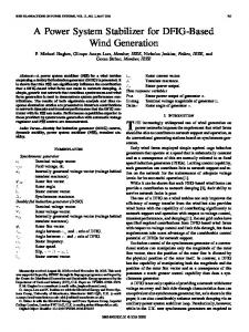
Forklift is widely used in many areas. It is needed forklift simulators to reduce the possible accidents caused by user errors and environmental circumstances and to train operators. The forklift simulator is consisted of a real forklift cabin, simulation screens, simulation computer on 6 DOF Stewart
parameters in dynamic model such as; speed, acceleration, direction and lifter position and animated to simulation screens. Meanwhile these physical parameters are used for motion control of 6 DOF platform. A simplified diagram of the system is presented in Fig.l.
Platform and trainer screens. Designed system transmits the data acquired from equipments such as lever, pedals, steering mechanism and buttons to the simulation computer and the commands sent from simulation computer shift the position and states of gauges and warning lights.
$IIIFf..g:r•
SREIING
1H.TI.MII
MEOtANSM
SI6NAI.«LT SENSOR
61U1615AND U6tfrS
CiEAR.fIOItN
The designed
measurement unit transfers data between simulator computer and simulator via CAN-Bus. CAN-Bus is widely used especially for communication among vehicle electronic systems and so on thanks to its low
ANAlOG MOIJUIf
cost and easy applicability [I]. Comparison of the advantages and disadvantages of CAN-Bus among the other protocols is given
in
Table
I.
According
to
the
comparison
of
communication protocols, RS485 does not have collision detection mechanism so it needs a network master. However, it reduces the communication speed. Ethernet protocol is more
ISBN: 978-1-4673-5613-8©2013 IEEE
Fig. I Block diagram of CAN based simulator system
498
I
Ill.
SYSTEM MODEL
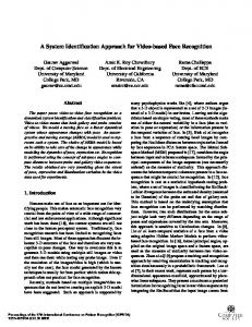
CAN Network of forklift simulator is modelled in RTaW
0,7 ms
Sim CAN-Bus simulator [3] for analyzing the CAN frame
0,65ms
response times and statistics. The virtual CAN network shown in the Fig.2, contains simulation computer, digital input-output module and analog input module nodes. There are 10 frames defined with different identifiers that send periodically between 3 nodes at 1 Mbps baud rate.
0,6 ms
� O,55ms
.5 0,5ms '";;0,45ms '" .1; 0,4ms
� O,35ms &.
0,3ms
100,25ms ICII:: O,2ms 0,15ms
Canld
ShortName
Type
Sender
Receivers.
P ayload
21/0>