CIRED
18th International Conference on Electricity Distribution
Turin, 6-9 June 2005
DETECTION, LOCALIZATION AND INTERPRETATION OF PARTIAL DISCHARGE IN THE UNDERGROUND DISTRIBUTION NETWORK AT HYDRO-QUÉBEC D. Fournier*, B. Cantin**, J. M. Bourgeois**, F. Léonard**, Y. Roy**, J. Fournier**, J. Caron** * Réseau souterrain, Hydro-Québec, Canada, ** IREQ Hydro-Québec, Technologie et dév. Industriel, Canada
[email protected]
INTRODUCTION Most of power failures occur at cable joints in Hydro-Québec underground conduit network. Some are due to partial discharges inside these joints and the corresponding degradation of their electrical insulation. Hydro-Québec Distribution conduit network consist mainly of XLPE cable with rubber premoulded accessories. In 2001, Hydro-Québec started a research project for the diagnosis of underground cable and their accessories. This project was implemented for safety issues, to perform predictive maintenance and to withdraw defective accessories before failure. This paper describes ours experimental steps and our experience in the field: - statistical analysis of accessories failures in the field - analysis of the cause of partial discharge activity in cable accessories - study of the degradation of the insulation due to partial discharges - change in PD pattern with aging - setting up of the main parameters for the detection and localization of partial discharges - design and testing in the field of a prototype for the detection and localization of partial discharges sources.
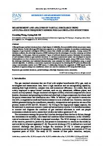
Fig. 1 Typical PD current pulse in cable accessory.
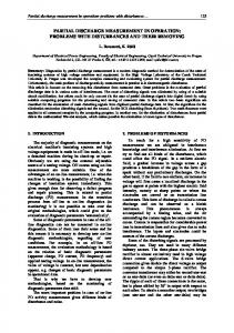
EXPERIMENTAL Laboratory An experimental set-up was built to study the long term (months to year) evolution of PD in cable accessories [1]. Indeed, homemade hardware and software allow us to monitor PD parameters such as intensity, pulse rise time, number per cycle, etc… all phased resolved. Figures 1 and 2 shows two displays of our software. PD pulse in cable accessories can have rise time from below 1 nsec up to 15 nsec. Normally, PD activity lies in the first ant third quadrant of the 60 Hz high voltage. We have currently, four experiments going on at the same time: two load break elbow and two cable splice. These premoulded accessories come from the field and they all had PD at 1 U0 (14.4 kV).
Fig. 2 Phased resolved of PD intensity with time.
A vault would be put under strict restrictive access if a lineman detects a signal 10 dB above the ambient noise when probing a cable accessory. This restrictive access forbids any worker to get in the vault unless the defective line is deenergized. This restriction goes on until the cable accessory has been replaced. While this PD detector has good detection sensitivity, it has several flaws [2]:
On Line PD Field Measurements
•
Hydro-Québec has been using a commercial portable PD detector since 1994. This device is basically a narrow band (around 7 MHz) AM receiver with a small capacitive probe. Linemen are presently using it.
•
CIRED2005 Session No 1
low immunity to aerial RF coupled on distribution lines no discrimination capacity towards conducted RF signal (other than PD signal) traveling through the distribution line
It is thus very difficult to determine whether or not a signal
CIRED
18th International Conference on Electricity Distribution
Turin, 6-9 June 2005
measured with this device is really coming from a PD source inside a cable accessory under test. Finally, these flaws generate lots of false ‘positive’ diagnosis and therefore numerous costly unnecessary ‘vault access restriction’ and equipment replacements [2]. Hydro-Québec new portable PD analyser In view of the situation described above, Hydro-Québec needed a new portable device for the detection, localization and interpretation of PD in cable accessories. The main characteristics of our new device (see fig. 3) are: •
Wide bandwidth measurements. Each PD pulse is recorded, filtered and analyzed (see fig. 4)
•
Phased resolved PD detection (see fig. 5)
•
Probes are shielded from capacitive coupling
•
Analog and numerical filtering
•
Automated software for the detection, discrimination among spurious RF signals and localization of PD sources (see fig. 6)
Fig. 4 Filtered and analysed PD pulse. Here one can see a PD pulse in a cable splice and its reflection from a nearby manhole.
Fig 5 On line phased resolved PD detection (60 Hz) in a cable splice.
Fig. 3 Portable Hydro-Québec apparatus for field PD detection and localization.
Finally, this device is presently used in the field to verify the validity of the vaults restrictions generated by the commercial portable PD detector described at the beginning of this section.
Fig. 6 Final diagnosis and statistics.
RESULTS AND DISCUSSION As mentioned before, the portable commercial PD detector has been used for ~10 years. As of today, Hydro-Québec is plagued with ~500 vault restrictions in its underground distribution network. Each restriction costs ~15 k$ mainly due to replacement of cable and accessories and manpower. We have so far verified over 100 vault restrictions with our new PD apparatus. We have performed in these vaults over 600 PD measurements. We found that more than 95% of the CIRED2005 Session No 1
CIRED
18th International Conference on Electricity Distribution
Turin, 6-9 June 2005
vault restrictions are not justified. Concerning the equipments with real PD activity, we found 3 transformers, 1 SF6 switchgear, 4 load break elbow connectors, 1 transition splice (PILP to XLPE cables), 2 separable connectors, 1 thermo retractable splice and 2 bad ground connections in vaults. Selected field cable accessories with PD have been monitored for 1 to 2 years. Our purpose here is to study the field evolution of PD activity and time to breakdown of these cable accessories. Field case stories In Montréal suburb, we had 8 manholes with strong signal measured with the commercial PD detector, which resulted in 8 vault restrictions. Thanks to our new PD device, we first concluded that cable splices in these vaults were PD free. We also quickly localized (see fig. 7) the source of this signal. Indeed, a transformer 2 km away had strong PD activity. This PD activity generated RF signal travelling in the underground distribution lines and was therefore «polluting» a portion of the distribution network.
Fig. 8 Infrared image of a cable splice at 14,4 kV, no current load. Note the abnormal heat ring near the center.
Fig. 9 Analysis showing that the recorded PD pulse is coming from the defective cable splice.
Fig. 7 Localization, in one hour, of a strong PD source. Each blue arrow is a measurement point and indicates the direction of the PD RF related signal. A defective transformer was finally found 2km away of the first measurement.
In Montréal downtown area, a cable splice with PD and an abnormal heat ring was found. Figure 8 shows an infrared image of this splice at 14.4 kV with no current load. Analysis (see fig. 9) performed by our software indicates that PD pulses had a high frequency content and that they all originated (see fig. 10) from the defective cable splice with the abnormal heat ring. Moreover, the phase resolved analysis (see fig. 11) shows an unusual 90° shift in the occurrence of PD.
CIRED2005 Session No 1
Fig. 10 Final diagnosis and statistics related to the defective cable splice.
Explanations for the abnormal heat ring and the 90° shift in PD occurrence had to be found. The defective cable splice was therefore X-rayed. Radiographic images showed that the inner semi-conductive layer (semi-con) was partially in contact with the high voltage aluminium conductor. Moreover, a cavity was observed near the edge of the semicon exactly were the heat ring occurred. Electrical tracking was also observed on the upper side of this cavity. Figure 12 shows an equivalent circuit which explains the 90° shift in the occurrence of the PD activity and the abnormal heat ring. Normally, an equivalent circuit does not have a
CIRED
18th International Conference on Electricity Distribution
leakage resistance in parallel with Cb [1]. In this case, the current I (the charge displacement) is 90° in advance of the power voltage. The voltage at Cc is then in phase with the power voltage. That is why most PD occurred in the 1st and 3rd quadrant of the power voltage cycle, where the maximum dV/dT lies (see fig. 5). In our specific case, our X-ray images shows that the cavity Cc, where PD activity occurred, is feed in charges through the inner semi-con which is the leakage resistance Ll. The current and voltage at Cc are then respectively in phase and ~ 90° late with the power voltage. This explains the 90° lag observed on figure 11 since PD occurred mostly at the maximum dV/dT. Remember that this situation results from the bad adhesion of this semi-con to the inner aluminum conductor at high voltage. Finally, losses related to Rl caused the heat ring observed on figure 8.
Turin, 6-9 June 2005
(a range from 100 metres to few kilometres) of equipment plagued with PD (transformer, switchgear and cable accessories). Our experimental and fieldwork show that PD in premoulded accessories last from months to years before final breakdown. Infrared images are also very useful to detect defects in accessories that will eventually degrade and develop PD activities Our work demonstrates that a too hasty field introduction of a commercial PD detector with not enough performance can be very costly. Final development of the new Hydro-Québec PD device is under way and commercial grade units will be available later next year. ACKNOWLEDGMENT We would like to thank all the HQ-Distribution and IREQ employees (engineers, technicians and linemen) who contributed to this project. They were very helpful in providing us with a laboratory truck and with field samples. REFERENCES
Fig 11 The phased resolved detection for the defective cable splice shows that PD activity is shifted 90°. All PD pulses occur in the 2nd and 4th quadrants.
Fig. 12 Equivalent circuit of a PD in a cavity with a leakage resistance. Ca is the bulk capacitance; Cb is the lump capacitance between the cavity and both the ground and high voltage; Cc is the cavity capacitance and Rl is the leakage resistance.
CONCLUSION Field PD measurements are not an easy task. Underground distribution lines are usually polluted by many RF signals. Therefore one needs leading edge electronic equipments and ‘rugged’ algorithms to measure tiny PD signals in such environment. Localization of a PD source in the field is even more demanding. Hydro-Québec new PD device exhibits excellent field performance. For the first time, Hydro-Québec has a realistic picture of the PD phenomena in its distribution network. Moreover, this device can perform remote on-line detection CIRED2005 Session No 1
[1] D. Fournier, B. Cantin, J.-M. Bourgeois, C. Larose, Y. Roy, F. Léonard, R. L’Écuyer, S. Poirier, 2003, “Rapport synthèse étape II, projet «Diagnostic des lignes souterraines de distribution »; volets décharges partielles et mitigation des ondes de chocs”, HydroQuébec report: IREQ-2003-100C [2] D. Fournier, B. Cantin, N. Amyot, C. Larose, M. Foata, C. Comte, E. David, 2001 “Etat de l’art et identification des options”, Hydro-Québec report: IREQ-2001-160C