It is widely acknowledged that nanoelectronic devices will suffer from more manufacturing and operational faults than classical CMOS devices in large-scale ...
Developing Fault Models for Nanowire Logic Circuits Daniel Gil, David de Andrés, Juan-Carlos Ruiz, Pedro Gil Fault Tolerant Systems Research Group (GSTF), Universidad Politécnica de Valencia (UPV) DISCA – ETS Informática Aplicada, Campus de Vera s/n, E-46022, Valencia, Spain Phone: +34 96 3877007 Ext {75777, 75752, 85703, 79707}, Fax: +34 96 3877579 {dgil, ddandres, jcruizg, pgil}@disca.upv.es Abstract It is widely acknowledged that nanoelectronic devices will suffer from more manufacturing and operational faults than classical CMOS devices in large-scale integrated circuits. The confident use of these emerging technologies relies on our capacity to better understand their fault mechanisms, and our ability to deduce related fault models. These challenging goals are addressed in this paper for nanowire logic circuits, which constitute one of the most promising technologies in the nanoelectronics realm. Fault models are proposed attending to how fault mechanisms manifest at device and logic abstraction levels. This research is framed within a more global investigation focused on the development of suitable dependability assessment methodologies and defect and fault tolerance strategies for systems built-up using nanodevices.
1. Introduction As CMOS technology enters the nanoelectronics realm (tens of nanometres and below), where quantum mechanical effects start to prevail, conventional CMOS devices are meeting many technological challenges for further scaling. This situation has motivated the increasing emergence of a variety of new nanoelectronic devices [1] [2]. As new generations of nanodevices are developed, we become less familiar with their fault mechanisms and the causes behind their failures [3]. On the one hand, the nature of the materials and the physical phenomena used in these technologies are very different from current CMOS. On the other hand, it is widely acknowledged that the very small sizes of the resulting devices will provoke higher levels of manufacturing defects than those affecting present-day CMOS solutions. In addition, transient (or permanent)
IEEE/IFIP DSN-2008
in-service faults will have to be dealt with [4]. So reliability is a big challenge in nanoelectronic devices and architectures. The confident use of the emerging technologies relies on our capacity to better understand their fault mechanisms, and our ability to develop related fault models. Those fault models can be considered as a step forward towards the dependability assessment of emerging architectures for the definition of new and efficient fault mitigation techniques [5]. Among the wide set of new proposed nanoelectronic devices, 1D structures (Carbon Nanotubes (CNTs) and Nanowires (NWs)) are one of the most promising to develop logic circuits [6]. A number of factors (scalability, performance, energy efficiency, gain, operational reliability, room temperature operation, CMOS technological compatibility, and CMOS architectural compatibility) have been evaluated to establish the potential use of different nanodevices. 1D structures present the best results in most of these factors. In addition, reconfigurable architectures based on the use of programmable gate logic arrays are suggested for 1D structures. The use of simple, regular, crossbar structures seems to offer the best chance for eventually fabricating nanocomputers with more than 1010 devices per chip. So we will focus our study on 1D structures and, more particularly, on nanowires. First of all, the analysis of both CNTs and NWs exceeds the extension of this paper. Secondly, NWs offer some interesting advantages over CNTs, such as the ability of manipulating and assembling NWs into different structures and the difficulty in controlling the electronic properties of nanotubes [7]. This paper focuses on the analysis of the main manufacturing defect causes and mechanisms of nanowire-based logic circuits. It allows the definition of fault models at device and logic abstraction levels, which will enable the development and precise
2nd Workshop on Dependable and Secure Nanocomputing, June 27, 2008
Page 1/6
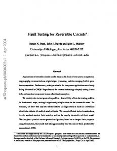
parameterisation of fault-tolerant schemes for nanoelectronic systems in future works. Figure 1 shows the applied methodology, which determines the manifestation at the device and logic abstraction levels of manufacturing defects in nanowires. Hence, it is necessary to understand the hierarchical structure of logic circuits at different abstraction levels, i.e. the structure of logic circuits consisting of nanowire-based devices (diodes and transistors).
Figure 1. Applied methodology: study of fault manifestation at higher abstraction levels.
Section 2 presents a brief description of semiconducting nanowires and the main devices and logic circuits that can be designed with them. Section 3 studies fault causes and mechanisms related to manufacturing defects, which leads to the identification of fault models at device level. Fault models of some representative logic circuits are defined in Section 4. Finally, Section 5 provides some conclusions and proposals for future work.
2. Semiconducting nanowires Nanowires (NWs) are long thin wires made up of semiconducting materials, such as silicon or germanium. They have been fabricated with diameters as small as 3 nm and lengths of up to hundreds of micrometers [8]. The most successful method of controlled growth is VLS (Vapour-Liquid-Solid) synthesis [8] [7]. VLS growths crystalline structures using a liquid catalyst seed such as gold or iron, at high temperature. The catalyst absorbs the vaporized NW materials (silicon or germanium plus a possible dopant) until it becomes supersaturated, at which point a solid crystal begins to form. NWs will continue growing until the catalyst is cooled and becomes solid, or the vaporized crystalline material is used up. When dopant materials are added to the vapour, NWs will become semiconducting (ptype or n-type, depending on the dopant). NWs can conduct like a metal if they are highly doped. The controlled growth of NWs also allows for the doping to be varied along the length of the NW. NWs exhibit some advantages over the nanotube counterpart. NWs synthesis techniques provide a high
IEEE/IFIP DSN-2008
degree of control over their chemical composition, physical dimensions, and electronic and optical properties. This control provides many more active device possibilities for NWs. On the other hand it is difficult to control the properties of nanotubes.
2.1 Electronic devices with nanowires By controlling the doping profile along the length of the NW, active devices can be constructed [8]. A diode can be obtained in two different manners. One method consists in crossing one p-type and one ntype semiconducting NWs, creating a connection and therefore a p-n junction. The other procedure is based on creating a p-n junction in the same nanowire, growing part of the nanowire with a p-type dopant and then changing to an n-type dopant for the remainder of the nanowire. A field effect transistor (FET) can also be created by crossing two nanowires. One of them has a low doped region that works as the transistor channel. The other is placed over the top of this region, with an insulator separating the two wires. The top wire controls the current in the bottom wire. An alternative design consists in using nanowires as the channel in a more conventional FET, similar to what is done with carbon nanotubes [9].
2.2 Logic circuits with nanowires A Diode-Resistor Logic like structure is proposed in [7] as a possible way to implement AND and OR gate designs. As Figure 2c shows, diodes consist of nanowire crosspoints and resistors are based on crosspoint NWFETs. In this way, two-dimensional crosspoint structures can be used to implement simple and regular designs.
Figure 2. AND gate designed with nanowires [7]. A pseudo-NMOS (in this case pseudo-PMOS) like structure is also proposed in [7] to implement NAND and NOR gate designs. Figure 3 shows the design of the NOR gate. As before, FET transistors and resistors are built as regular two-dimensional structures made of crosspoint NWFETs.
2nd Workshop on Dependable and Secure Nanocomputing, June 27, 2008
Page 2/6
Figure 3. NOR gate designed with nanowires [6]. It is possible to build complex circuits extending the previous structures. AND/OR arrays of programmable crosspoints can be used to design Programmable Logic Arrays (PLA), memory cores and programmable crossbar interconnect arrays [8] [10]. Programmable crosspoints exhibit hysteresis and non-volatile state storage in order to work as programmable diodes or as non-volatile read/write memory cells. Figure 4 roughly reproduces the structure of a PLA OR plane, comprising a diode-programmable wired-OR NW, followed by a field-effect inverter NW for signal restoration [10]. Crosspoints can be programmed on/off by programming their resistance into low or high states. Programmable crossbar arrays can be built from the wired-OR programmable array, as long as each output connects with only one selected input. This allows routing any input to any output. This structure can be useful to avoid defective resources in a post-fabrication phase.
Figure 4. Scheme of an OR nanoPLA plane with signal restoration [10].
3. Fault models at device level for manufacturing defects Some defects have been reported in nanowires and crosspoints [10]. Nanowire defects include broken wires, doping variations, and poor contacts. Defects in programmable crosspoints lead to non-programmable crosspoints or shorted crosspoints. Although defects related to the bridging of adjacent nanowires have been also reported, lesser incidence is expected. Our goal is to analyse how these defects manifest at the device abstraction level and suggest fault models at this level. The knowledge of the structure of nanowire devices (diodes and transistors) is therefore necessary. The fault models development are summarised in the following paragraphs and in Table 1.
Table 1. Fault models at device level for manufacturing defects in nanowires. Causes and mechanisms Fault models at device level (manufacturing defects [10]) Diodes FETs I/O connections Broken wires open open open Nanowire defects Poor contacts delay delay delay Doping variation delay delay delay Open crosspoint open/missing* open Crosspoint defects Short crosspoint short/extra** short Imperfect alignment short short short Bridging of adjacent nanowires Shell thickness variations short short short * In programmable circuits: missing devices due to permanent off crosspoints ** In programmable circuits: extra devices due to permanent on crosspoints
NWs may break along their axis during assembly, due to mechanical stress in high length-to-diameter ratio wires. As it was shown in section 2.1, nanowires can constitute I/O connections, p-n junctions or the channel of FET transistors. The consequence of this defect, and our proposed fault model, may be an open (the current intensity becomes null) in nanowire-based devices (diodes and transistors) and I/O connections. Poor contacts due to statistical number of atomic scale bounds will increase the wire resistance out of the designated resistance range. This defect can provoke a
IEEE/IFIP DSN-2008
variation of the timing RC constant in I/O connections and devices. Delay is thus the proposed fault model. Statistical doping may lead to an excessive variation in the NW doping which can push its resistance out of the designated range and provoke timing faults. The suggested fault model is also delay, although the timing variation in this case can be positive or negative. Junctions between crossed NWs consist of tens of atoms or molecules and the individual bond formation is statistical in nature. Open and short defects can occur in crosspoint junctions, leading to open and short fault models for devices. In programmable circuits,
2nd Workshop on Dependable and Secure Nanocomputing, June 27, 2008
Page 3/6
such as PLAs, defects can manifest as nonprogrammable or shorted crosspoints, which cannot be programmed into the on- or off-state, respectively. This leads to missing or extra devices in the array [11]. Other defect is the bridging of adjacent nanowires. Imperfect planar NW alignment and variations in core shell thickness are potential causes of bridging and can lead to obvious shorts between I/O connections or device terminals. Radial shells around the (semi) conducting NW cores prevent the shorting of adjacent NWs, and of gated and control wires in transistors. As previously stated, it is also necessary to study faults occurring during normal operation. Wear out processes can lead to permanent faults, and some environmental agents may produce transient ones. Possible fault mechanisms related to wear out include mechanical stress, thermal processes, and electrostatic discharge, like in carbon nanotubes [12] [13]. On the other hand, external agents like thermal fluctuation and cosmic radiation can cause transient faults in nanowire devices. It is expected that transient faults will have a high impact on these small devices [6]. Fault models for wear out processes and environmental agents in nanowires will be the subject of future research.
4. Fault models at logic level It is first necessary to obtain the hierarchical structure of the device-based logic circuit. Then, the analysis of faults propagation and manifestation at logic level will be based on the previously defined device-level fault models (see Table 1). Although this work assumes single and independent faults, the high defect rate of new nanodevices suggests the interest of a future analysis of the effect of multiple faulty devices. This methodology has been applied to two examples: a single gate and programmable circuits.
4.1 Example 1: AND gate This first example deals with the AND gate whose design and structure can be seen in Figure 2. It consists of the following devices: two diodes and one resistor, all of them based on nanowire crosspoints. Figure 5 summarises the hierarchical structure, the fault models at device level which are derived from Table 1, and the proposed fault models at logic level.
Figure 5. Hierarchical structure and fault models for the AND gate.
IEEE/IFIP DSN-2008
2nd Workshop on Dependable and Secure Nanocomputing, June 27, 2008
Page 4/6
Fault models for defects in diodes and resistors are explained by means of diagrams on the right side of Figure 5. They are obtained by applying the fault models at device level to the electronic circuit of Figure 2b. Due to their complexity, some of them have been obtained after PSPICE simulations. It must be noted that defects in the wire connections between the devices have been also considered. Open faults due to broken wires may manifest as open faults in the devices. Delay faults in devices due to poor contacts or doping variation may provoke delay faults in the gate. The bridging of adjacent wires can lead to shorts between input-output, input-input or inputcontrol signals. In the first case the result is an obvious stuck-at. In the second one, the bridging can produce power supply shorts or error value 1Æ0 faults, depending on the source of the inputs. The last fault
model is derived assuming that the two shorted signals come directly from the supply layers. In summary, a wide set of fault models have been defined, although the most frequent may be logic value error, mainly due to defects in the diodes.
4.2 Example 2: programmable circuits This second example refers to programmable circuits, such as PLAs or non-volatile memories based on two-dimensional arrays of programmable crosspoints that act as programmable diodes or memory cells. Figure 6 summarises the hierarchical structure, the fault models at device level and the proposed fault models at logic level.
Figure 6. Hierarchical structure and fault models for programmable circuits. In memory cells, defects may manifest as open or short of programmable crosspoints, as shown in Table 1. This forces the content of the cell to one logic value and therefore the assigned fault model is stuck-at. This study has considered two subcircuits of the PLA structure: the OR array of diodes and the restoration array (see Figure 4). The OR array comprises the programmable diodes and the static load of each output. Defects in programmable diodes imply missing or extra diodes (see Table 1). This manifests as
IEEE/IFIP DSN-2008
logic value errors, as depicted in the related figures. Defects in the static load manifest as open/short fault models at the crosspoint. These, in their turn, may manifest as high impedance or stuck-at at logic level, as figures show. Finally, the restoration circuit consists of three NWFETs, as shown in Figure 4, for each output of the array. They form a dynamic like inverter structure, and each transistor is based on a nanowire crosspoint. From open and short fault models at device level (see Table 1), six cases can be easily analysed for
2nd Workshop on Dependable and Secure Nanocomputing, June 27, 2008
Page 5/6
the three transistors. Open faults in the precharge/ evaluate transistors prevent the discharge/charge of the output capacitance and may provoke logic value errors 0Æ1/1Æ0 (respectively), as shown in related figures. Short faults in precharge transistor produce an obvious stuck-at-0 fault in the output. Short faults in the evaluate transistor may manifest in a more complex way. As the related figure shows, a “0” input during precharge cause a contention because both pull-up and pull-down transistors will be ON, and the output cannot be guaranteed to be “0” during precharge. This results in an indetermination fault model. Finally, open/short faults in the input FET avoid/force the charge of the output capacitance in the pull-up subcircuit, which can manifest as logic value error 1Æ0/0Æ1 (respectively). The programmable crossbar array is a particular case of a PLA structure, as stated in Section 2.2. Then its proposed fault models match those of PLAs. Defects of I/O interconnection nanowires have not been studied in this work, due to the complexity of the circuit, although their fault models seem to be similar. As in the previous example, a wide set of fault models have been obtained. The most frequent ones in PLAs and crossbar arrays may be those related to defects in programmable diodes, which are the most abundant devices. Specifically, logic value errors due to missing and extra diodes. In memory cores the predominant fault model is stuck-at.
5. Conclusions and challenges This work has presented a study about the definition of fault models for nanowire logic circuits. Nanowire devices are widely acknowledged as very promising nanodevices to build logic circuits due to their good properties. In addition, reconfigurable architectures based on the use of programmable gate logic arrays are suggested for nanowire structures. We have analysed the effects of nanowire manufacturing defects in logic circuits following a bottom-up methodology. The fault manifestation from the physical to the device and, from here, to the logic abstraction level has been studied. This process needs the previous definition of the hierarchical structure of the considered logic circuits at the different levels. This methodology, which will greatly benefit from the use of CAD tools for the simulation of nanowire-based device models, can be applied to any logic circuit regardless its complexity. Two examples of different complexity have been analysed, and a wide set of fault models has been obtained, emphasizing the most frequent ones. Those fault models can be considered as a step forward towards the dependability assessment of
IEEE/IFIP DSN-2008
emerging architectures for the definition of new and efficient fault mitigation techniques. Some challenges requiring a further research include (i) the analysis of the effect of multiple faulty devices in nanowire circuits; (ii) the study of the faults produced during operation, particularly, wear out processes and environmental agents that provoke transient faults in nanowire circuits; and (iii) a similar overall research for other promising devices (mainly carbon nanotube, spintronic and molecular devices).
6. Acknowledgements This work has been sponsored by the Spanish project MCYT TEC 2005-05119/MIC.
7. References [1] R. Waser, “Nanoelectronics Technology”, Wiley-VCH, 2003.
and
Information
[2] J. Han, “Fault-Tolerant Architectures for Nanoelectronic and Quantum Devices”, Ph.D. dissertation, Delft University of Technology, 2004. [3] W. Kuo, “Challenges related to reliability in nano electronics”, IEEE Trans. on Reliability, vol. 55, no. 4, 2006. [4] R. Forshawet al., “Nano_Arch_Review”, IST Programme (Future and Emerging Technologies), 2004. [5] D. Gil, et al., “Identifying Fault Mechanisms and Models of Emerging Nanoelectronic Devices”. IEEE Int. Conf. on Depend. Syst. and Networks, Edinburgh, UK, pp. 288, 2007. [6] International Technology Roadmap for Semiconductors (ITRS): Emerging Research Devices, 2007. [7] Z. M. Nuseibeh and A.M. Halawani, “Electronic Components using SiNWs”, Electrical and Electronic Engineering Department, Imperial College London 2006. [8] M. Haselman and S. Hauck, “The Future of Integrated Circuits: A Survey of Nano-electronics”, Submitted to Proceedings of IEEE, 2007. [9] G. W. Hanson, “Fundamentals of Nanoelectronics”, Pearson-Prentice Hall, 2008. [10] Dehon, “Nanowire-based Programmable Architectures”, ACM Journal on Emerging Technologies in Computing Systems, Vol. 1, No. 2, pp. 109-162, July 2005. [11] W. Rao, et al., “Fault Tolerant Approaches to Nanoelectronic Programmable Logic Arrays”, IEEE Int. Conf on Dependable Syst. and Networks, Edinburgh, UK, 2007. [12] L. Anghel, “Conception Robuste dans les Technologies CMOS Avancées et post-CMOS“, Lab. TIMA, 2007. [13] T. Dang, “Nanotubes de carbone, SET et QCA en logique: modélisation de fautes“, Lab. TIMA, 2005.
2nd Workshop on Dependable and Secure Nanocomputing, June 27, 2008
Page 6/6