Journal of Medical and Biological Engineering, 23(3): 149-158
149
Development of 3D Navigation System for Retained Auricular Prosthesis Application Chung-Hsien Kuo
Ming-Yih Lee*
Kai-Feng Hung1
Chiung-Shing Huang1
Yi-Shan Chiu
Department of Mechanical Engineering, Chang Gung University, Tao-Yuan, Taiwan, 333, ROC 1 Craniofacial Center, Chang Gung Memorial Hospital, Tao-Yuan, Taiwan, 333, ROC Received 10 Aug 2003; Accepted 3 Sep 2003
Abstract Computer aided surgery (CAS) had been an important research topic in recent years. 3D navigation is the crucial technique in the CAS applications. In this paper, a sound-guided 3D navigation system used for the retained auricular prosthesis surgery wad developed. This system consists of a 3D digitizer arm, a 3D space coordinate transformation module and a sound-guided navigation module. A 3D digitizer is a 5 degree-of-freedom passive robotic arm, and it is used to measure the coordinates of the registration and implant landmarks of the patient. The measured coordinates of landmarks are further compared with the patient’s 3D reconstruction computer model that is constructed in terms of the computed tomography (CT) images to calculate the coordinate transformation matrix. The transformed implant coordinates are desired for the real-time navigations. In addition, the proposed sound-guided navigation module provides the real-time surgical guidance based on different audio tones and intermittence frequencies to improve the surgical accuracy. Finally, a clinical study of the retained auricular prosthesis surgery is introduced in this paper. Based on the results of the clinical validation, the proposed system effectively assistants the surgeon to increase the surgical quality and reduce the surgical time as well. Keywords: Microtia, Retained auricular prosthesis surgery, Computer aided surgery, Medical mechatronics
Introduction The term of “microtia” [3, 5, 10] is a combination of the words of the “micro” and “otia” literally; the micro indicates small and the otia indicates ear. Microtia is a congenital deformation with incompletely formed ear. Due to the auricle developing from tissues of the branchial arches, the facial deficiency is common for the microtia patient. The photo of the abnormal ear of the microtia patient is shown in Fig. 1. When the ear deformity occurs in conjunction with other facial deficiencies, the “hemifacial microsomia” is one of the most common conditions. It appears as a flattened side of the face, and it is an underdevelopment of the bony jaws and overlying soft tissues. In addition to the artificial ear reconstruction, the retained auricular prosthesis surgery is one of the most suggested ear reconstruction surgeries. Computer aided surgery (CAS) [1-2, 5-8] is getting more popular and important to the clinical medicine in recent years. The CAS integrates the techniques of information system, 3D *Corresponding author: Ming-Yih Lee Tel: +886-3-2118800 ext. 5340; Fax: +886-3-2118037 E-mail:
[email protected]
coordinate transformation, computer graphics and navigation, and the knowledge of the clinical medicine to assist the surgical navigations. The CAS aims to increase the quality and precision of the surgery and to reduce the surgical time as well. In 2002, Paglia et al. [6] proposed the computer aided surgery planning for the knee surgery. The authors developed a system for the tri-dimensional reconstruction of the knee’s structure. The cartilage segmentation was reconstructed based on the magnetic resonance imaging (MRI). In addition, Dohi et al. [2] also proposed a computer aided surgery system in 1990. The proposed CAS developed a surgical simulation and planning environment based on the three-dimensional reconstruction model. A clinical trail of this system for a surgical planning and a prognosis of the liver carcinoma were discussed. The results showed a great possible use in the abdominal surgery. Kuo et al. [5] proposed a conceptual design of the image-based and CT-free solution for the retained auricular prosthesis surgery in 2002. In this work, the image processing, landmark recognition and real-time navigation were done based on three diagonal digital images, as shown in Fig. 2. However, many CAS systems are expensive and time consuming, and the surgeons must learn additional skills in
150
J. Med. Biol. Eng., Vol. 23. No. 3 2003
Figure 1. Photo of the abnormal ear of the microtia patient
The image processing technique is used to recognize the craniofacial characteristics and ear contour features from each sliced computed tomography (CT) image. The 3D reconstruction technique [2, 6] is used to reconstruct the 3D surface model for the further computer-based pre-surgical planning and simulation. In addition, it can also be used to produce a physical rapid prototyping (RP) model using a RP machine. Especially, the localizations of the surgical landmarks can be identified and assigned in terms of the 3D reconstructed model. The data acquisition technique is realized using the 3D digitizer arm, and it can acquire the coordinates of the space points. The kinematic transformation technique is developed to calculate the transformation matrix between the coordinates of the computer model and the space coordinate acquisition from the patient. The sound-guided navigation technique uses different audio tones and intermittence frequencies to guide the operation of the surgery by calculating the distance between the implant positions of the pre-planed computer model and the patient. The software engineering technique is used to develop a user-friendly graphical user interface to simplify the operation of the surgery. The proposed surgical protocol that integrates the previously described techniques was verified by the surgical expertise. In order to validate the proposed navigation system, a rapid prototyping head physical model that is identical to the patient’s head was produced for the surgical rehearsal. Finally, a clinical study of a microtia patient had been evaluated using the proposed 3D sound-guided navigation system.
Materials and Methods Figure 2. Retained auricular prosthesis surgery based on three diagonal digital images [5]
Figure 3. Projection of the normal ear contour to the abnormal ear side using distance measurements
operating the complex calibration, navigation, and surgical procedures [8]. In this paper, a sound-guided 3D navigation system was proposed for the retained auricular prosthesis surgery. This system integrates the techniques of the image processing, 3D reconstruction, data acquisition, kinematic transformation, sound-guided navigation, and software engineering.
Quick Review of Traditional Retained Auricular Prosthesis Surgery The ear reconstruction surgeries of the microtia patients can be categorized into the “artificial reconstruction ear” and the “rib reconstruction ear”. The retained auricular prosthesis surgery uses the rib reconstruction ear for the ear reconstruction. In this section, the procedures of the traditional retained auricular prosthesis surgery for the unilateral abnormality are introduced. For the traditional retained auricular prosthesis surgery, the surgeons must markup the surgical landmarks on the patient’s face initially. The surgical landmarks are determined by measuring the distances between the central line of the nasal and the normal ear contour. Then, the normal ear contour is mirrored to the abnormal ear side in terms of the previously measured distances as the surgical landmarks. Fig. 3 shows the photo of the operations for such procedures. In addition, the landmarks can also be identified in terms of sketching the normal ear contour using a transparency film, and then mirroring it to the abnormal era side, as shown in Fig. 4. Eventually, the determined implant contour of the rib reconstruction ear is shown in Fig. 5. On the other hand, the procedures of reconstructing the rib reconstruction ear are introduced. The rib reconstruction ear is carved from the patient’s rib cartilage. The cartilage
3D Navigation System
Figure 4. Projection of the normal ear contour to the abnormal ear side using transpartancy film
Figure 5. Determined implant contour of the rib reconstruction ear
Figure 6. (a) Carved cartilage framework of the rib reconstruction ear; (b) photo of the constructed tragus; and (c) deepened conchal bowl of the reconstructed rib ear [10]
framework is formed to simulate the ear’s cartilage, as shown in Fig. 6 (a) [10]. Fig. 6 (b) shows the photo of tragus that has been constructed [10]. Finally, the conchal bowl can be deepened, and the shape of the reconstructed ear appears, as shown in Fig. 6 (c) [10]. Therefore, from the previously described surgical procedures, the determination of the implant landmarks is one of the most important factors to the success of the microtia surgery. However, the traditional landmark markup method heavily relies on the clinical experiences of the surgeons. In addition, due to the non-rigidity of the soft tissues of the nose tip, nasal and facial skin, the traditional method is not accuracy for localizing the implant landmark. Meanwhile, traditional method also lacks of the online evaluation mechanism.
151
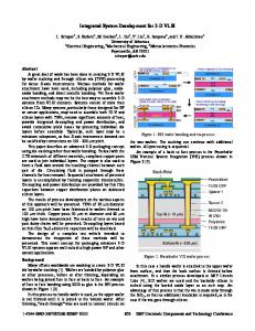
Architecture of Sound-Guided 3D Navigation System The proposed system development architecture is composed of the mechanical device, software component and audio guidance device. Fig. 7 shows the system development architecture. In this figure, the CT images are used to reconstruct the 3D computer model. The surgeons can use the 3D reconstructed model to define the registration and implant landmarks in the pre-surgery stage. In addition, the 3D reconstructed model can also be used to produce the physical RP head model for the further rehearsal. In order to illustrate the operational relationships among the components and devices, the system operation scenario is indicated as shown in Fig. 8. The proposed protocol is composed of two stages: the pre-surgery and in-process surgery stages. For the pre-surgery stage, the CT images of the patient are used to reconstruct the 3D computer graphic model. The CT images are loaded and transformed to the stereo lithography (STL) format using the Mimics software [9]. The image processing is used to recognize the images for the further 3D reconstruction. Such a reconstructed 3D computer model can be used to identify and assign the registration and implant landmarks in the pre-surgery stage. The patient’s head 3D computer model is shown in Fig. 1. The surgeon can identify and markup the surgical landmarks on the 3D computer model. Although such works are similar to the traditional procedures that were described in the pictures of from Fig. 2 to Fig. 4, the landmarks are more accurately identified and assigned than the traditional one. In the 3D computer model, the contour of the normal ear can be precisely mirrored to the abnormal side. The mirror plane for the mirror of normal features to the other side can be found by using the Mimics software and the FreeForm. The Freeform consists of a 3D force feedback mechanical arm and a 3D visualized windows application program, and it is a product of SensAble Technologies (MA, USA) [11]. Initially, the patient’s facial 3D computer model was allocated at the center position of the software. Then, the center of the nose was tried to align with the sagittal plan and make the left face and right face to be symmetric to such a plan. The sagittal plan is defined as the mirror plane in this work. The surgical landmarks are further categorized into the “registration landmarks” and the “implant landmarks”. Consequently, the landmarks are recorded in the database for the accessing of the in-process surgery stage. The “registration landmarks” are defined as the points on the upper face that must be clearly and easily identified such as the nose tip, slot between two front incisor teeth, and so on. They are required to be identified for the coordinate transformations between the patient’s upper face and the corresponding computer 3D graphic model. Note that there are at least three characteristics landmarks that are not collinear to be defined as a unique plane. On the other hand, the “implant landmarks” are defined as the space points that the rib reconstruction ear can be implanted. Such “implant landmarks” are determined using the geometric computing of mirroring the contour of the normal ear side. Therefore, the coordinate transformation matrix can be calculated in terms of the “registration landmarks” of the real patient’s upper face
152
J. Med. Biol. Eng., Vol. 23. No. 3 2003
Figure 7. Sound-guided navigation system development architecture
Figure 8. System operation protocol
and the 3D computer graphic model. The patient’s implant landmark can be further calculated from the transformation matrix and the “implant landmarks” of the computer model. Fig. 9 illustrates the details of the coordinate transformation relationships. In the in-process surgery stage, the surgeon acquires the coordinates of the registration landmarks from the patient’s
face using the 3D digitizer. The 3D digitizer arm is a five-degree-of-freedom passive robot arm with 10-3 inch resolution. The coordinates of the end point can be calculated using the forward kinematics. In addition, this work develops a windows-based software application program to guide the surgeons to reach the pre-registered landmarks using the Microsoft Visual C++[4]. The software application is designed
3D Navigation System
M2(M21,M22,M23) N2(N21,N22,N23)
M1(M11,M12,M13) N1(N11,N12, N13)
153
M4(M41,M42,M43) N4(N41,N42,N43)
M5(M51,M52,M53) N5(N51,N52,N53)
M3(M31,M32,M33) N3(N31,N32,N33)
Registration Landmarks
M6(M61,M62,M63) N6(N61,N62,N63)
Implant Landmarks (a)
M4 M1
M5
M3
N1 N-Coordinate N3 Patient Model
M6 M2
Transformation
M-Coordinate Computer Model
N2
N6
N4 (b)
N5
Figure 9. (a) Representation of landmarks; and (b) coordinate transformations
to enable the 3D digitizer arm communication, calculate the coordination transformation matrix, and guide the 3D digitizer arm to reach the physical implant positions. In order to calculate the transformation matrix, the physical coordinates of the patient’s registration landmarks are cooperated with the registration landmarks of the computer graphic model to calculate the transformation matrix. Meanwhile, the coordinates of the implant landmarks of the computer graphic model are transformed to the 3D digitizer arm (i.e., patient) coordinates for the further navigation. The audio guidance device is composed of a speaker. The audio sounds are desired to inform the implant location identifier and the distance between the actual implant position and end point of the 3D digitizer arm in terms of different audio tones and intermittence frequencies. Landmark Coordinate Transformations In this paper, the landmarks are used to identify the 3D coordinates of the registration and implant locations in the pre-planned and in-process stages. The coordinate transformation problem [1] can be described as: given M1, M2, M3, M4, M5, M6, N1, N2, and N3, and find N4, N5, and N6, as shown in Fig. 9. By defining the matrices of MC (computer registration), NC (patient registration), MI (compuetr implant), and NI (patient implant) as the landmark coordinate matrices of the computer model and the patient, respectively.
M 11 MC = M 21 M 31
M 12 M 22 M 32
M 13 M 23 ; NC= M 33
N 11 N 21 N 31
N 12 N 22 N 32
N 13 N 23 (1) N 33
M 41 MI = M 51 M 61
M 42 M 52 M 62
M 43 M 53 ; NI = M 63
N 41 N 51 N 61
N 42 N 52 N 62
N 43 N 53 N 63
(2)
Now translate MC by M1 in M-coordinate such that M1 reaches the origins; and translate NC by N1 in N-coordinate such that N1 also reaches the origins to obtain the relative coordinates matrices of ∆ MC and ∆ NC, respectively.
M11 − M11 M12 − M12
M13 − M13 P1
∆ MC = M 21 − M11 M 22 − M12 M 23 − M13 = P2 ; (3) M 31 − M 11 M 32 − M 12 M 33 − M 13 P3
N11 − N11 N12 − N12 N13 − N13 Q1 ∆ NC = N 21 − N11 N 22 − N12 N 23 − N13 = Q2 N31 − N11 N32 − N12 N 33 − N13 Q3
(4)
Therefore, MC = M1 + ∆MC
(5)
NC = N1 + ∆NC
(6) T
T
Note that P1 = [0 0 0] ; Q1 = [0 0 0] ; Pi = [Pix Piy Piz]T ; and Qi = [Qix Qiy Qiz]T. The coordinate transformations can be calculated in terms of the following steps. Step 1: Rotate P2 to the X-Z plane in M-coordinate with respect to x-axis with angle θMyz = tan-1(P2y / P2z) as P2’. The transformed P2’ can be written as P2’ = [P2x’ P2y’ P2z’]T = R Myz P2 .
154
J. Med. Biol. Eng., Vol. 23. No. 3 2003
Figure 10. Navigation application program
1 0 0 where R Myz = 0 cos(θ Myz ) − sin(θ Myz ) 0 sin(θ Myz ) cos(θ Myz )
(7)
Similarly, the N-coordinate can also be transformed in the same manner, θNyz = tan-1(Q2y/Q2z) as Q2’. The transformed Q2’ can be written as Q2’= [Q2x’ Q2y’ Q2z’]T = R Nyz Q2 .
1 0 0 where R Nyz = 0 cos(θ Nyz ) − sin(θ Nyz ) 0 sin(θ Nyz ) cos(θ Nyz )
(8)
Step 2: Next, rotate P2’ again to the Y-Z plane in M-coordinate with respect to y-axis with angle θMxz =-tan-1(P2x’ / P2z’) P2”. The transformed P2” can be written as P2” = [P2x” P2y” P2z”]T = R Mxz P2’ .
cos(θ Mxz ) 0 sin(θ Mxz ) 0 1 0 where R Mxz = − sin(θ Mxz ) 0 cos(θ Mxz )
(9)
Similarly, the N-coordinate can also be transformed in the same manner, θNxz= - tan-1(Q2x’/Q2z’) as Q2”. The transformed Q2” can be written as Q2”= [Q2x” Q2y” Q2z”]T = R Nxz Q2’ .
cos(θ Nxz ) 0 sin(θ Nxz ) 0 1 0 Where R Nxz = − sin(θ Nxz ) 0 cos(θ Nxz )
(10)
Step 3: Now, P2” and Q2” have only z-axis with nonzero components in the M-coordinate and N-coordinate,
respectively. Next, transform P3” and Q3” again as P3”’ and Q3”’ such that P3”’ and Q3”’ are in the same direction. Note that, P3” = [P3x” P3y” P3z”]T = R Mxz R Myz P3 ; and Q3”= [Q3x” Q3y” Q3z”]T = R Nxz R Myz Q3 . Rotate P3” to the X-Z plane in M-coordinate with respect to z-axis with angle θMxy = tan-1(P3x” / P3y”) as P3”’. The transformed P3”’ can be written as P3”’ = [P3x”’ P3y”’ P3z”’]T = R Mxy P3” .
cos(θ Mxz ) − sin(θ Mxz ) 0 where R Mxy = sin(θ Mxz ) cos(θ Mxz ) 0 0 0 1
(11)
Similarly, the N-coordinate can also be transformed in the same manner, θNxy =tan-1(Q3x” / Q3y”) as Q3”’. The transformed Q3”’ can be written as Q3”’ = [Q3x”’ Q3y”’ Q3z”’]T =R Nxy Q3” .
cos(θ Nxz ) − sin(θ Nxz ) 0 cos(θ Nxz ) 0 where R Nxy = sin(θ Nxz ) 0 0 1
(12)
Consequently, P2” = P2”’ ; and Q2” = Q2”’. Now, P1”’ and Q1”’ are equal to [0 0 0]T ; P2”’ and Q2”’ are in the same direction ; and P3”’ and Q3”’ are in the same direction. From ∆MC”’= [P1”’ P2”’ P3”’]T ; and ∆NC”’= [Q1”’ Q2”’ Q3”’]T, and they are not essentially equal. Therefore, it is required to introduce a scaling factor, fMN to make ∆MC”’and ∆NC”’ to be identical. fMN = Q2z”’/ P2z”’.
(13)
Hence, ∆NC”’ = fMN × ∆MC”’. Step 4: Finally, The transformation relationships between M-coordinate and N-coordinate can be desired. From ∆NC”’= [Q1”’ Q2”’ Q3”’]T, it is noted that:
3D Navigation System
155
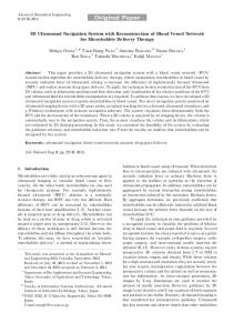
Results In this section, the implementation and clinical study are introduced. The proposed system is operated based on the windows-based application program. The modules of application program are composed of the 3D digitizer communication, data acquisition, pre-registered landmark loading, coordinate transformations, error calculating, and sound-guided navigation. The navigation application program is shown in Fig. 10. In this figure, the control icons indicate the operation procedures of this system, and they are the “connecting the 3D digitizer arm”; “enabling the 3D digitizer arm space point acquisition”; “saving the landmarks and results”; “initializing new operation”; “loading pre-stored landmarks”; “calculating the transformation matrix”; “starting the navigation”; “stopping the navigation”; “setting the error range”; and “calling for online help”. In addition, the coordinate information relating to the surgery can be seen form the windows view. Note that the unit uses the inch. The system had been clinically validated in Chang-Gung Memorial Hospital, 2001. The system setup is shown in Fig. 11. In order to validate the proposed process, a rapid prototyping (RP) head physical model that is identical to the patient’s head was produced, as shown in Fig. 11. The proposed methodology was first clinically held in our university and Chang Gung Memorial Hospital, Although the authors had confidence within the proposed surgical navigation, a RP head model based rehearsal really decrease the risk of the surgery. In addition to validate the proposed methodology, the surgeon suggested us to use a physical RP head model for the surgical rehearsal in the first trial. Consequently, it is necessary to have the RP model for surgical rehearsal. The rehearsal was held before this surgery. The photo of using the proposed system and the 3D digitizer is shown in Fig. 12. Finally, the completely marked implant rib reconstruction ear contour shown in Fig. 13 was extended as the contour which was plotted by the surgeon. In order to make consistent mapping between Fig. 9 (a) and Fig. 13, the implant landmarks were further identified in this figure.
Figure 11. System setup and RP head model
Figure 12. Surgery of using the proposed system
Discussion Figure 13. Implant rib reconstruction ear contour
∆MC”’ = R Mxy R Mxz R Myz ∆MC
(14)
∆NC”’ = R Nxy R Nxz R Nyz ∆NC
(15)
∆NC
= R Nyz R Nxz R Nxy ∆NC”’ = fMN ×(R Nyz)-1 (R Nxz ) -1 (R Nxy) -1 ∆MC”’
= fMN ×(R Nyz)-1(R Nxz ) -1(R Nxy) -1R Mxy R Mxz R Myz ∆MC = Rtrans ∆MC (16) Consequently, from (5-6) NC = N1 + Rtrans ∆MC
(17)
Finally, such transformation is valid for any points in the M-coordinate and N-coordinate. Therefore, the NI can be solved form the knowledge of the Rtrans and MI.
Because the three registration landmarks are not well identified on the real soft tissues of the patient, it is difficult to select identical landmarks on both the patient and the 3D model. In order to validate the accuracy the of navigation algorithm and the procedures of the practical operation, the registration and implant landmarks were pre-marked using small tips from the CT reconstruction model as the validation marker. Since the RP head was produced from the marked CT reconstruction model, the small tips were also found in the RP head. Hence, the proposed rehearsal validation accuracy can be achieved within 0.5 mm with computer re-slicing technique to refine the resolution of the CT image model. On the other hand, the thickness of CT slicing was 1 mm. The results shown in Table 1 was measured based on the result of one of the “rehearsal” trials. The gray area indicates
156
J. Med. Biol. Eng., Vol. 23. No. 3 2003
Table 1. Space coordinates of the registration and implant landmarks
Computer Model Coordinate in Pre-Surgery Stage X (inch) Y (inch) Z (inch)
3D Digitizer Coordinate in In-Process Surgery Stage X (inch) Y (inch) Z (inch)
Registration Landmrak 1
12.788
-1.204
6.636
-2.345
15.105
6.686
Registration Landmrak 2
13.156
-0.801
4.878
-2.654
15.639
4.977
Registration Landmrak 3
9.107
-0.945
6.361
-3.941
11.799
6.393
8.004
-1.454
6.32
-3.865
10.632
6.309
8.774
-1.301
5.723
-3.751
11.411
5.737
9.342
-1.192
4.602
-3.691
12.004
4.643
Implant Landmrak 1 Implant Landmrak 2 Implant Landmrak 3
inch
X-Coordinate Tracking
Ditigizer Implant Target
0 -2 -4 -6 -8 -10
Z-Coordinate Implant Desired Target
-12 -14
(a) inch
Y-Coordinate Tracking
Digitizer Implant Target
16 14 12 10 8 6
Y-Coordinate Implant Desired Target
4 2 0
(b) inch
Z-Coordinate Tracking
Digitizer Implant Target
8 6 4
Z-Coordinate Implant Desired Target
2 0
(c) Figure 14. Plots of X-Y-Z coordinate tracking for the implant landmark # N4
the transformed implant landmarks. The rehearsal procedures also followed the protocol as indicated in Fig. 8. The registration and implant landmarks of the computer model were generated from the pre-marked small tips, and they are shown in the left hand side of this table. On the other hand, the
registration landmarks of the RP physical head were identified from the small tips on the physical RP head using the 3D digitizer. The acquired space coordinates of registration landmarks of physical RP head were indicated in the right-upper part of Table 1. Based on the computing of the
3D Navigation System
kinematic transformation technique, the transformed theoretical implant landmarks were indicated as shown in the right-down part of Table 1. Finally, the implant positions were determined using the sound-guided navigation module and a 3D digitizer. The surgeon can determine the implant positions in terms of different audio tones and intermittence frequencies. Once the implant position is determined, the space coordinates of implant landmarks in physical RP head were recorded. In addition, the determined implant positions can be marked on the physical RP head, and they can be compared with the small tips of the implant landmarks to get the accuracy of the navigation system. By recording the trajectory of the real-time navigation of the 3D digitizer arm, the error value of the final implant location is approximately 0.5 mm. That is, the pre-assigned implant landmarks can all be accurately reached. Fig. 14 shows the trajectory of implant landmark # N4 (referred to Fig. 9). Note that the unit of Fig. 14 is “inch”. This figure indicates the navigation history of (X,Y,Z) coordinates of implant landmark of “N4”, and the navigation history of (X,Y,Z) coordinates were acquired using the 3D digitizer in terms of 0.01 second sampling time. It is noted that the horizontal lines in three coordinate tracking figures indicate the desired (i.e., that is transformed from the CT computer model) coordinates of the axes of X, Y, and Z. On the other hand, the registration and navigation times were also reduced based on the investigations of 10 times practical RP head model based “rehearsal” trials. Based on these investigations, the registration and navigation times can be reduced within 3 minutes. In this work, one clinical case was reported. Therefore, this system actually increases the surgical quality and reduces the surgical time.
graphical model will be included in this application program. In this manner, the vision-based navigation technique can be cooperated with the current sound-based navigation technique to provide more surgical navigation information. In addition, the results of this work will be modified to apply to the other clinical studies such as the orthopaedic surgeries.
Acknowledgements This work was partially supported by the Medical Mechatronics Education Resource Center, Ministry of Education, Taiwan, R.O.C., under the 2001 Student Hand-On Competition Project. The authors also acknowledge the clinical supports from the Craniofacial Center, Chang-Gung Memorial Hospital.
References [1]
[2]
[3] [4]
[5]
Conclusions In this paper, the 3D navigation system for retained auricular prosthesis application is proposed. The techniques of the image processing, 3D reconstruction, data acquisition, kinematic transformation, sound-guided navigation, and software engineering were integrated to complete this work. The proposed system reduces the complex procedures of the traditional retained auricular prosthesis surgery. In addition, the surgery quality is improved, and the surgery time is reduced. Especially, it is a low cost solution when compared to the imaged-sensor based navigation system. Finally, a clinical study of the retained auricular prosthesis surgery had been validated. In the future, the real-time 3D animation computer
157
[6]
[7]
[8] [9] [10] [11]
M.H. Davis, A. Khotanzad, D.P. Flamig, S.E. Harms, “Coordinate Transformation in 3D Image Matching by a Physics Based Method-Elastic Body Splines,” Proceedings of International Symposium on Computer Vision, 218-222, 1995. T. Dohi, Y. Ohta, M. Suzuki, K. Chinzei, T. Horiuchi, D. Hashimoto, M. Tsuzuki, “Computer Aided Surgery System (CAS): Development of Surgical Simulation and Planning System with Three Dimensional Graphic Reconstruction,” Proceedings of the First Conference on Visualization in Biomedical Computing, 458-462, 1990. J. Fearon, A Guide to Understanding Microtia, Children's Craniofacial Association (www.ccakids.com), 1993. D.J. Kruglinski, Inside Visual C++ - The Standard Reference for Programming with Microsoft Visual C++, Version 4, Washington:Microsoft, 1996. C.H. Kuo, J.A. Ku, M.Y. Lee, and S.C. Huang, “Development of Computer-Aided and Image-Guided Retained Auricular Prosthesis Surgery,” CD Proc. of 2002 IEEE/ASME International Conference on Advanced Manufacturing Technologies and Education in the 21st Century, Taiwan, Paper ID: B121, 2002. M. La Paglia, J.H. Kuiper; J.B. Richardson, L. McCall, C. Ruggiero, “3D Processing of MRI Images of the Knee for Computer Aided Surgery Planning,” Proceedings of the IEEE-EMBS Special Topic Conference on Molecular, Cellular and Tissue Engineering, 188-189, 2002. R.A. Robb, D.P. Hanson, J.J. Camp, “Computer-Aided Surgery Planning and Rehearsal at Mayo Clinic,” Computer, 29: 39-47, 1996. http://www.brainlab.com/scripts/website_frame_english.asp?la nguage=E http://www.materialise.be/mimics/main_ENG.html http://www.microtia.com/whatis.html http://www.sensable.com