Anal Bioanal Chem (2008) 391:2365–2370 DOI 10.1007/s00216-008-2163-0
TECHNICAL NOTE
Development of an automated system for isolation and purification of humic substances André van Zomeren & Esther van der Weij-Zuiver & Rob N. J. Comans
Received: 12 February 2008 / Revised: 24 April 2008 / Accepted: 25 April 2008 / Published online: 17 May 2008 # Springer-Verlag 2008
Abstract Characterization of humic substances (HS) in environmental samples generally involves labor-intensive and time-consuming isolation and purification procedures. In this paper, the development of an automated system for HS isolation and purification is described. The novelty of the developed system lies in the way the multiple liquids and columns used in the isolation/purification procedure are handled in both forward and back-elution mode by solenoid valves. The automated procedure significantly reduces the total throughput time needed, from 6–7 days to 48 h, and the amount of labor to obtain purified HS for further characterization. Chemical characterization of purified HS showed that results were in good agreement with previously published values for HS from a variety of sources, including the IHSS standard HS collection. It was also shown that the general properties of HS were consistent among the different source materials (soil, waste, aquatic) used in this study. The developed system greatly facilitates isolation and characterization of HS and reduces the risk of potential Electronic supplementary material The online version of this article (doi:10.1007/s00216-008-2163-0) contains supplementary material, which is available to authorized users. A. van Zomeren : E. van der Weij-Zuiver : R. N. J. Comans (*) Energy Research Centre of The Netherlands (ECN), Post Office Box 1, 1755 ZG Petten, The Netherlands e-mail:
[email protected] R. N. J. Comans Department of Soil Quality, Wageningen University, P.O. Box 47, 6700 AA Wageningen, The Netherlands Present address: E. van der Weij-Zuiver Chefaro Nederland BV, P.O. Box 6014, 3002 AA Rotterdam, The Netherlands
(time-dependent) alteration of HS properties in the manual procedure. Keywords Natural organic matter . Humic acid . Fulvic acid . Isolation . Purification . IHSS method
Introduction Natural organic matter (NOM) in the environment can be of plant, animal, or microbial origin and may range from relatively fresh to highly decomposed and transformed. NOM plays an important role in, for example, soil properties such as cation-exchange capacity, soil structure, water entry and retention, nutrient cycling, and binding of heavy metals and organic micropollutants [1, 2]. The study of these properties often requires isolation and purification of organic matter. Currently, the International Humic Substances Society (IHSS) uses the adapted fractionation method of Aiken [3], earlier described in detail by Thurman and Malcolm [4], for isolation and purification of humic (HA) and fulvic acid (FA) standards from aqueous samples, and the method of Swift [2] for solid source materials. These methods are based on precipitation of HA at pH 1 or 2 and adsorption of HA and/or FA on the macroporous XAD-8 resin. Adsorbed HS are subsequently desorbed with 0.1 mol L−1 NaOH and cations are removed by a cation-exchange resin. The reader is referred to Refs. [2–5] for detailed descriptions of the methods of isolation. Although these procedures are well established and widely used by scientists, they all share the disadvantage of being very laborious, particularly because of the manual handling of the multiple liquids and columns that are required.
2366
Anal Bioanal Chem (2008) 391:2365–2370
first cleaned to remove organic impurities by five consecutive 24-h extractions with 0.1 mol L−1 HCl and 0.1 mol L−1 NaOH. Fine floating particles were removed by decantation. The XAD-8 and the cation-exchange resin (Biorad AG-MP-50, 100-200 mesh) resin were thoroughly cleaned by Soxhlet extraction with acetonitrile and methanol, each for 24 h. The cleaned resins were stored in methanol until use.
This paper describes the development of an automated system to perform isolation and purification of HS, especially from solid source materials. The setup of the system is very flexible and easy to modify, which allows methods that involve HA separation after prior preconcentration and purification (e.g. Thurman and Malcolm [4] and Leenheer [5]). However, these methods then involve intermediate HA separation by acidification and centrifugation. The novelty of the method lies in the automated handling of the multiple liquids and columns, required in the isolation/purification procedure, in both forward and back-elution mode. The particular experimental set up allows the procedure to be executed with only a single pump and flowmeter. Our main objective for automation of the IHSS procedure was to save a significant amount of labor and total throughput time in the performance of HS isolation and purification. By automating the procedure, our objective is also better standardization of the HS isolation and purification methods.
Samples
Materials and methods
The automated procedure was performed (according to Swift [2]) on a peat (Devoke UK), a compost sample, a landfill waste mixture, and a sample of municipal solid waste incineration (MSWI) bottom ash. Moreover, HS from four aquatic samples, a landfill leachate, influent and effluent water from a landfill water treatment plant, and water from a DOC-rich pond in a nature reserve (Zwanenwater, NL), were isolated and purified according to Thurman and Malcolm [4]. All purified HS (except from MSWI bottom ash) were also characterized by the method of van Zomeren and Comans [6].
Reagents
Hardware
All reagents used were of analytical-grade quality. Double demineralized water (nanopure) was used for preparation of reagents. Every new batch of XAD-8 (Amberlite) was
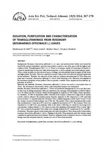
The experimental setup of the procedure is outlined in Fig. 1. The lines in the scheme represent Teflon tubing (FEP, 1/8″ O.D., 1/16″ I.D.) connected to several two-way
Sample 1 (FA1)
no S1 nc
I1
Water
I8
I3
Sample 2 (FA2)
I9
Pump
*
I5
FA3
unadsorbed XAD-4
I 10
I4
FA1 + FA2
unadsorbed FA1 + FA2 S6 MeOH 0,1 M HCl no nc 0,01 M HCl
I7
I2
0.1 M NaOH
I 12
nc
no S2
no S3
CB1
CB2
CA4
CB3
CA5 Column 5
CA3 Column 4
CA2 Column 2
CA1
Column 3
nc
CB4
CB5
nc S5
no
no
nc S4
Flowmeter Fraction collector F1 F2 F3 F4 F5 F6 F7 F8 F9 F10
10 % HCl
I 11
I6
Column 1
Fig. 1 Schematic representation of the automated isolation and purification system. An asterisk marks the manual option (Omnifit manual three-way connector, part: 1102) to de-aerate the tubing and the pump before each experiment. Dashed lines mark connections from fractions that are first produced (F2 and F4) in the procedure and that are later used in subsequent elution steps (FA1 + FA2 and FA3). N2 gas was supplied to the eluate FA3 (fraction 4) until it was purified by the cation-exchange resin. Sample vessels F2 (containing 6 mol L−1 HCl and concentrated HF) and F4 were placed on a magnetic stirrer with a Tefloncoated magnet to homogenize the solution
N2 supply for fraction 4
XAD-4-NaOH
Anal Bioanal Chem (2008) 391:2365–2370
2367
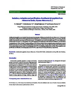
Table 1 Procedure statements used to perform the isolation and purification procedure of Swift [2] Step
Description
Stop volume
Column
Fraction
Flow
Deviation
1 2 3 4 5 6 7 8 9 10 11 12 13 14 15 16 17 18 19 20 21 22 23
Pumping water through column 4 (i2) Pumping 10% HCl through column 4 (i11) Pumping water through column 1 (i2) Pumping water through column 2 (i2) Pumping water through column 3 (i2) Pumping 0.01 mol L−1 HCl through column 1 (i8) Pumping FA1 through column 1 (i1) Pumping 0.65 column volumes of water through column 1 (i2) Back-eluting with 1.5 column volume of 0.1 mol L−1 NaOH (i3) Back-eluting with 3.5 column volumes of water (i2) Pumping 0.01 mol L−1 HCl through column 2 (i8) Pumping FA2 through column 2 (i4) Pumping 0.65 column volumes of water through column 2 (i2) Back-eluting with 1.5 column volumes 0.1 mol L−1 NaOH (i3) Back-eluting with 3.5 column volumes of water (i2) Pumping 0.01 mol L−1 HCl through column 3 (i8) Pumping FA1+FA2 through column 3 (i5) Pumping 0.65 column volumes of water through column 3 (i2) Back-eluting with 1.5 column volumes 0.1 mol L−1 NaOH (i3) Back-eluting with 3.5 column volumes of water (i2) Pumping water through column 4 (i2) Pumping FA3 through column 4 (i6) Pumping 2 column volumes of water through column 4 (i2)
20×cv4 15×cv4 20×cv1 20×cv2 20×cv3 1.5×cv1 0.95×FA1 0.65×cv1 1.5×cv1 3.5×cv1 1.5×cv2 0.98×FA2 0.65×cv2 1.5×cv2 3.5×cv2 1.5×cv3 4.9×(cv1+cv2) 0.65×cv3 1.5×cv3 3.5×cv3 20×cv4 4.9×(cv3) 2×cv4
4 4 1 2 3 1 1 1 1 1 2 2 2 2 2 3 3 3 3 3 4 4 4
3 3 3 3 3 3 1 1 2 2 3 6 6 2 2 3 1 1 4 4 3 5 5
fl4 0.6×fl4 fl1 fl2 fl3 fl1 fl1 fl1 fl1 fl1 fl2 fl2 fl2 fl2 fl2 fl3 fl3 fl3 fl3 fl3 fl4 fl4 fl4
5 5 5 5 5 5 5 5 5 5 5 5 5 5 5 5 5 5 5 5 5 5 5
The steps are executed in increasing number until the stop volume is reached. Sample (FA1/FA2) and column volumes (CV) are entered by the user in the user interface and the flow (FL) is derived from these volumes (default: 5 CV h−1 ). Column number, fraction number, and the deviation in the stop volume (%) are given for each step
used in the database (see “Software” section) to specify their function (Tables 1 and 2). The position of the fraction collector is denoted F1-10 (Fraction). The two-way valves that control the liquid to be pumped are named I1-
(Takasago, type, 24 V DC) and three-way solenoid valves (Furon, model 1101493, 24 V DC) by Omnifit PEEK fitting nuts (part 2222) and grippers (part 2312). All valves and fraction-collector positions of the system were named and
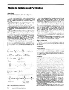
Table 2 Modbus addresses and status of the solenoid valves in each step of the isolation and purification procedure according to Swift [2] Modbus 22 Address Step/Valve S1 1 2 3 4 5 6 7 8 9 10 11 12 13 14 15 16 17 18 19 20 21 22 23
23
24
25
26
27
0
1
2
3
4
5
6
7
8
S2
S3
S4
S5
S6
I1
I2
I3
I4
I5
I6
I7
I8
I9
9
10
11
12
13
14
15
16
17
18
19
20
21
I10 I11 I12 CA1 CA2 CA3 CA4 CA5 CB1 CB2 CB3 CB4 CB5
The grey cells indicate that the appropriate valve is opened during the specific step in the procedure
2368
12 (input). The system contains two blocks (Takasago, MTV-2-6NMFG-1, 24 V DC) with six solenoid valves (manifolds). Additionally, two manifolds (Takasago, MTV2 -5NMFG-1, 24 V DC) with five valves above and below the columns are named CA1-5 and CB1-5 (Column), respectively. The system was developed to perform the isolation and purification procedures of Swift [2], Thurman and Malcolm [4], and Leenheer [5]. Therefore, the connections and liquids for all of these methods are addressed in Fig. 1 (e.g. liquid inputs I8, I9, and I12). The six three-way valves (S1-6, Switch) were used to reverse the flow to perform back elution during recovery of the purified HS. The normally open (no) and normally closed (nc) positions of the valves are noted in Fig. 1. Glass columns (Omnifit 2.5 cm I.D.×40 cm for XAD-8 and Omnifit 1.5 cm I.D.×40 cm for AG-MP-50) were used and the adjustable endpieces (2008NS and 6465NS) were equipped with 100 μm PTFE frits (6243NS). All liquids were pumped (ProMinent Verder; Type: GALA1602TTT000UA002000) after the appropriate set of valves was opened (Tables 1 and 2). To reduce pressure pulses from the pump, either silicone tubing (0.7 mm I.D., 1 mm O.D.) or special crimped flexible PTFE tubing (3 mm I.D., 5.5 mm O.D., Polyfluor, NL) can be installed behind the pump. The flow was measured with a liquid flowmeter (G.J.C. Instruments, model 5025500) and adjusted to the set point value by the software. A home-made rotating fraction collector collected the eluates in the various bottles using a stepper motor (Astrosyn, Y129, art. 586389, 12 V DC, 0.16 A). The home position (fraction number 1) was determined with an inductive sensor (Balluff, BES 5163005-E4-C-PU-05). Communications The data I/O system contains several modules (Wago) for control of the valves, pump, inductive sensor, and stepper motor. All modules and their functions are specified in Table S1, the connections are shown in Figure S1 (Electronic Supplementary Material). The I/O modules were connected to the fieldbus network system (Modbus/ RS232 communication) by a fieldbus controller (750-814), which was connected to COM1 of the PC. The second serial port of the PC (COM2) was used to communicate with the liquid flowmeter (RS232). Software The software was developed to control the pump, valves, flow meter, and fraction collector and includes a user interface to specify experiments. During the experiment the current status of each step is displayed and the user is allowed to stop or pause the experiment. Liquid volumes,
Anal Bioanal Chem (2008) 391:2365–2370
elapsed time, flow, and experiment set points are written to a data file. A Flow diagram showing the sequence of events during execution of a typical experiment is shown in Fig. 2. The software can be obtained from the authors free of charge. The experimental configuration, procedure definitions (Table 1) and Modbus protocol register addresses (Table 2) were stored in a MS Access database. Elemental analysis of purified HS The elemental composition (CHNO) of the purified HS (after drying at 110 °C) was analyzed with a Carlo Erba
Read a record from the database table (StepMain or StepsPurge) Move the fraction collector to the desired position Open the appropriate valves
Evaluate the formulas for the stop volume and the flow Send the flow set point to the pump While the calculated volume is less than the stop volume: 1. Calculate the volume if a flow value is received from the flowmeter 2. Adjust the flow if necessary 3. Check the stop and pause button in the user interface Else : go to next event Switch off pump, close valves and write data to data file While the current step number