The Ninth International Conference on Electronic Measurement & Instruments
ICEMI’2009
Development of an Electromechanical Sensor System to Monitor Sports Activities Yull Heilordt Henao
Fabiano Fruett
Department of Semiconductors, Instruments and Photonics, University of Campinas Av. Albert Einstein, 400, CEP 13083-970, Campinas, SP, Brazil Email:
[email protected] and
[email protected]
Abstract – This paper proposes the development of a low cost electronic non-invasive comfortable prototype based on acceleration and rotation microelectromechanical (MEMs) sensors for obtaining physiological measures during training or regular physical activities of a chosen athlete. In this paper we present the prototype system; The system for acquisition, calibration and testing of accelerometer (SACTA) and some preliminary field tests. Keywords – Accelerometer, Sport Sensing, Real Time Feedback, Wireless Communication.
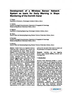
I. INTRODUCTION Fig. 1. Block diagram of the system prototype.
Currently advances on microelectronics and microelectromechanical sensors, which are each time smaller, low power consumption and affordable prices make more feasible and enable its application on sports. Accelerometers, gyroscopes, microphones and cameras all lend themselves suitable to a range of sports applications [1], making possible to obtain biomechanical, physical or cognitive information from monitoring the athletes performance during his/her training or sports practice. New Wireless communication standards like Bluetooth and Zigbee, provide a wireless platform to networking sensors, that can be widely applied in the healthcare sector as well as in sports [2] since it allow data transmission without interfering mobility. The athlete’s performance depends on the environment where he/she is being monitored [2], for example: laboratory, training, competition or playing field conditions. In addition to that, it is known that when feedback is provided in an appropriate manner, motor skill acquisition improves significantly. Consequently, feedback is a major factor in the improvement of sport skill performance [3], and besides systems with immediate feedback to the athelete increase motivation.
The prototype sensors were chosen taking into account the operation range, size, energy consumption, number of axes, type of output, encapsulation and price. In that way, the accelerometer MMA7260 from Freescale and the Gyroscope IDG-300 from InvenSense were chosen. With regard to microcontrollers, they were selected two eight bit chips from Freescale. They have low energy consumption, data bus over 10 MHz and SPI communication. The MC9S08Q which works with the sensors, has a ten bits and eight channels ADC and the HC908JW32 adds communications with USB 2.0 in the same circuit. The radiofrequency module is made up of a transceiver MC13191 from Freescale and the antennas. This module is appointed to operate in ISM (Industrial, scientific and medical) band with frequencies from 433 MHz to 2.4 GHz both sending and receiving signals [4]. Before assembling the mentioned prototype, a system to make acquisition, calibration and test of the MMA7260 and MMA7261 accelerometers (SACTA), was designed. These two accelerometers are totally pin-to-pin compatible but they have different sensitivity. III.
SACTA
II. SYSTEM PROTOTYPE Figure 1 shows the block diagram of the proposed prototype which is divided in two boards: the first one, (the upper part of the figure) has the acceleration and rotation sensors, a microcontroller, a radiofrequency module and a battery. This is the mobile part of the prototype and can be attached to the athlete’s body. The second board only has a microcontroller and the radiofrequency module which is connected directly to the USB plug of the computer in order to get the data.
_____________________________
The system to make acquisition, calibration and test of the accelerometers (SACTA) is represented in Figure 2. The SACTA is made up of the following components of hardware: An acceleration board for each one of the tested accelerometers (MMA7260 e MMA7261) (Figure 3), mechanical shaker for linear displacement (Figure 4(a)), rotation system, electronic circuit to make the frequency reading of the shaker motor (Figure 4(b)), power circuits for speed controlling of the shaker displacement and the rotation position and one data acquisition (DAQ) NI-USB-6251 from National Instruments. The software of
978-1-4244-3864-8/09/$25.00 ©2009 IEEE
4-6
Authorized licensed use limited to: UNIVERSIDADE ESTADUAL DE CAMPINAS. Downloaded on November 3, 2009 at 14:47 from IEEE Xplore. Restrictions apply.
The Ninth International Conference on Electronic Measurement & Instruments the entire system was developped on LabVIEW, which is a graphical programming language that has been widely adopted throughout industry, academia, and research labs as the standard for data acquisition and instrument control software [5]. This software allows the reading and writing into the tri-axis accelerometer, it controls speed of the shaker and reads the rotation speed of the motor as well. It makes the rotation control over a step motor, calibration, data processing and display of signals over a dynamic and easy interface to the user.
ICEMI’2009
purpose of the state machine is to provide defined responses to all events that can occur. This mechanism for control is easily implemented, is scalable for additional events, and always provides the same response mechanism to events [6].
Fig. 5. Frontal panel of the SACTA software.
Fig. 2. Block diagram of SACTA.
(a) MMA7261QT
1) Accelerometer calibration with SACTA: The two tested accelerometers presented an offset in all operational ranges. To eliminate this offset, a calibration process was developped. This process measured the gravity acceleration by each one of the accelerometer axes in three different positions, aligning the normal vector of the “Tic Tac sensor” box with the gravity vector in every position and keeping the other axis without acceleration, as it is represented in Figure 6.
(b) ”Tic Tac Sensor” Fig. 3. Accelerometers test boards.
(a) Position 1
(b) Position 2
(c) Position 3
Fig. 6. Tic Tac sensor axis orientation for SACTA.
For the calibration task, the program guides the user to align the sensor box in each one of the positions showed in Figure 7, and works out between the real acceleration data for each axes and the expected theoretical acceleration data. At the end, the offset value for every axis is saved in a file and read by SACTA during the startup.
(a)
Shaker with sensor
(b) Frequency reading circuit
Fig. 4. Mechanical shaker for linear displacement.
The software of the SACTA, has an user interface with three tabs of configurations: Principal panel, Configuration and Save; and six operation modes: Acquisition, Calibration, Rotation, Acquisition with rotation, Displacement and Acquisition with displacement. In Figure 5 is presented the Frontal panel of the program. Internally, the SACTA uses a state machine, which, in simple terms, is a case structure inside a While loop. The
(a) Position 1
(b) Position 2
(c) Position 3
Fig. 7. Accelerometer calibration positions.
Table 1 presents the offset values for every axis and for all sensibility range of the two accelerometers. Due to the linear response of the accelerometers [7] [8], these values 4-7
Authorized licensed use limited to: UNIVERSIDADE ESTADUAL DE CAMPINAS. Downloaded on November 3, 2009 at 14:47 from IEEE Xplore. Restrictions apply.
The Ninth International Conference on Electronic Measurement & Instruments
ICEMI’2009
are inverted and added to the acceleration signals of each one of the axis during all the acquisition process. Table 1. Calibration offsets.
(a) Range ±1.5 G
Table 2 presents the average values for every calibration positions in all sensors ranges. For the first four ranges (Accelerometer MMA7260), the maximum value between axes which must have equal accelerations in 0 m/s2 was 0.35 m/s2 and the minimal was 0.02 m/s2. Now, between axis that must have equal accelerations in -9.8 m/s2, the maximum value was -10.24 m/s2 and the minimum - 9.85 m/s2. For the second accelerometer (MMA7261) the peak values were a little higher as it is showed in bold in the same Table. We believe that these small offset values in the signals after the calibration process, are probably due to small sloppy during the soldering process of the QFN package, because the soldering was manually “home made” with hot air re-soldering station.
(b) Range ±6 G
Fig. 8. Acceleration of the MMA7260 under the same acceleration and diferents ranges.
To validate this measurement, the system calculates the theoretical acceleration based on the rotation frequency of the motor: where r it the radius and f is the motor frequency.
Table 2. Average values after calibration process. (a) FFT
(b) Acceleration signal
Fig. 9. FFT and acceleration on X axis for a range of ±6 G.
IV.
TESTS
The tests done in the mechanical shaker for linear displacement were divided into three stages: in the first one, the different ranges of sensor operation were tested, in the next, a filter was incorporated and finally a data process was added to get to the linear speed and the linear displacement from the filtered acceleration signal. It was clear that in the first stage the calibration process was successful and to make a good acceleration signal measurement, even in a known range, it isn’t advisable to limit the sensor range, since the signal can have vibration peaks which easily saturate the reading and can make it difficult to analyze the target signal. Figure 8(a) shows how vibration (±2 G) saturates the reading of the acceleration over the displacement axis Xc where the subscribe c identifies the calibrated axes. Before doing the filtration, a frequency analysis was done, using a FFT (Fast Fourier Transformer). It is shown in Figure 9. Next, it was filtered with a second order lowpass filter with cutoff frequency value of 20 Hz.
In Figure 10, we compare a theoretical acceleration with an acceleration measured by the sensor. We notice that as the calculated acceleration sense is negative, it must be compared with the negative peak of the sensor acceleration. In this case, it is presented a negative peak value of the sensor -0.8621 G and a calculated peak value of -0.7889 G. See the dash line in Figure 10(b).
(a) Lowpass filter in 20 Hz
(b) Theoretical acceleration based in the motor frequency
Fig. 10. Filter and theoretical acceleration on X axis for a range of ±6 G.
With the validation of the calibration and the acceleration magnitude read by the sensor, two integrals were added to data processing of the SACTA software to get a linear speed and the space or linear displacement of the platform, Figure 11 shows both. The maximum
4-8
Authorized licensed use limited to: UNIVERSIDADE ESTADUAL DE CAMPINAS. Downloaded on November 3, 2009 at 14:47 from IEEE Xplore. Restrictions apply.
The Ninth International Conference on Electronic Measurement & Instruments
ICEMI’2009
displacement of the mechanical shaker is equal to the radius between the mast and the center of rotation of the motor, equal to 0.02 m, (see the dash line in Figure 11(b)), compared with the peaks of displacement in the same figure, 0.01832 m we see that these values are very close.
Fig. 13. Frontal panel from LSM-ZSTAR software. (a) Speed
(b) Desplacement
Fig. 11. Speed and desplacement on X axis.
V. ZSTAR In a parallel way, the Demo board ZSTAR from Freescale was tested, this board has the same accelerometer tested by SACTA (MMA7260), one wireless communication module between the boards and USB communication with the computer [9]. The ZSTAR picture is presented in Figure 12.
(a) Position 1
(b) Position 2
(c) Position 3
Fig. 14. Tic Tac ZSTAR mobile board calibration positions.for LSMZSTAR.
(a) Position 1
(b) Position 2
(c) Position 3
Fig. 15. Tic Tac ZSTAR mobile board axis orientation for LSM-ZSTAR.
Fig. 12. Picture of ZSTAR DEMO board from Freescale.
We developed a program with LabVIEW to make the acquisition and calibration from the “Tic Tac ZSTAR mobile board” (Figure 14). The frontal panel of the LSM-ZSTAR program is showed in the Figure 13. The calibration process implemented in the ZSTAR was based on SACTA calibration process, but it had some important modifications, basically due to the axis orientation adopted in the firmware board (Figure 15) and the 3 V battery power supply. The last one is very important since we are testing a ratiometric accelerometer and both the offset and its sensibility are linear dependent of the power supply voltage.
adapted with a fixation system to let us fasten it to the athlete. In these bike testes, the sensor was fixed in the thigh and ankle of the athlete (Figure 16). In Figures 17, 18 and 19 each axe accelerations are compared for both sensor positions.
(a) LSM-ZSTAR
(b) Thigh
(c) Ankle
Fig. 16. Fixation system for fasten it at any corporal segment.
VI.
TEST IN THE FIELD
We made two field tests on bicycle using the ZSTAR board, which was encapsulated in a “Tic Tac box” and
In both tests the athlete started from zero (without motion). In the thigh test the pedaling was progressive from low to high intensity until stop. In the ankle test the athlete make ten pedal cycles at high intensity and stopped.
4-9
Authorized licensed use limited to: UNIVERSIDADE ESTADUAL DE CAMPINAS. Downloaded on November 3, 2009 at 14:47 from IEEE Xplore. Restrictions apply.
The Ninth International Conference on Electronic Measurement & Instruments The ten pedal cycles can be counted easily watching the accelerations peaks in the Yc axis in Figure 18(b).
ICEMI’2009
B. Future works In the next stage we will test the gyroscopes IDG-300 and IDG-1004 from InvenSense to get rotation information and incorporate into the final prototype system to monitor sports activities based in accelerometers and gyroscopes. ACKNOWLEDGEMENTS The authors acknowledge CNPq under Universal Project N 481412/2008-5 for the financial support.
(a) Thigh
(b) Ankle
REFERENCES
Fig. 17. Acceleration in the X axis. [1]
[2]
[3]
[4] (a) Thigh
(b) Ankle
[5]
Fig. 18. Acceleration in the Y axis. [6]
[7] [8] [9]
(a) Thigh
E. H. Chi, G. Borriello, N. Davies, and G. Hunt, “Pervasive computing in sport technologies,” IEEE ComSoc, IEEE CS, pp. 22–25, September 2005. S. Armstrong, “Wireless connectivity for health and sport monitoring,” British Journal of Sport Medicine, pp. 285–289, January 2007. D. G. Liebermann, L. Katz, M. D. Hughes, R. M. Bartlett, J. Mcclements, and I. M. Franks, “Advances in the application of information technology to sport performance,” Journal of Sports Sciences, vol. 20, pp. 755–769, January 2002. MC13192 Technical Data, Rev. 3.2 ed., Freescale Semiconductor, June 2007. J. Travis and J. Kring, LabVIEW for Everyone: Graphical Programming Made Easy and Fun, 3rd ed. Prentice Hall, July 2006. R. Bitter, T. Mohiuddin, and M. Nawrocki, LabVIEW Advanced Programming Techniques. Boca Raton, New York, London, Tokyo: CRC Press, 2001. MMA7261QT Technical Data, Freescale Semiconductor, February 2008. MMA7260QT Technical Data, Freescale Semiconductor, February 2008. P. Lajsner and R. Kozub, Wireless Sensing Triple Axis Reference Design: Designer Reference Manual, rev. 3 ed., Freescale Czech Systems Laboratories, Janeiro 2007.
(b) Ankle
Fig. 19. Acceleration in the Z axis.
VII.
CONCLUSIONS AND FUTURE WORKS
A. Conclusions The calibration process made with both SACTA and ZSTAR was successfully implemented, making it possible to compare the measured accelerations in magnitude with a minimum margin of error. The filtration process allied with a spectral analysis were essential to obtain a good relation between the real measure acceleration signal and the theoretical frequency based acceleration. The data integration stages to obtain the linear velocity and the linear displacement, were successful too. The displacement peak values were very close to the real ones. Finally in the preliminary field test, a good sensor fixation was made in the athlete and the signal doesn’t show any high noise component. The acceleration shape and amplitude in these bike tests will give and additional information to other most common parameters used in cycling like RPM and power.
4-10
Authorized licensed use limited to: UNIVERSIDADE ESTADUAL DE CAMPINAS. Downloaded on November 3, 2009 at 14:47 from IEEE Xplore. Restrictions apply.