energies Article
Development of Sliding Mode Controller for a ´ Modified Boost Cuk Converter Configuration Sanjeevikumar Padmanaban 1, * 1 2 3
*
ID
, Emre Ozsoy 1
ID
, Viliam Fedák 2 and Frede Blaabjerg 3
ID
Department of Electrical and Electronics Engineering, University of Johannesburg, Auckland Park 2092, South Africa;
[email protected] Department of Electrical Engineering and Mechatronics, FEI TU of Košice, Letná 9, 04200 Košice, Slovakia;
[email protected] Centre for Reliable Power Electronics (CORPE), Department of Energy Technology, Aalborg University, 9000 Aalborg, Denmark;
[email protected] Correspondence
[email protected]; Tel.: +27-79-219-9845
Received: 18 June 2017; Accepted: 13 July 2017; Published: 29 September 2017
Abstract: This paper introduces a sliding mode control (SMC)-based equivalent control method to a ´ novel high output gain Cuk converter. An additional inductor and capacitor improves the efficiency ´ and output gain of the classical Cuk converter. Classical proportional integral (PI) controllers are widely used in direct current to direct current (DC-DC) converters. However, it is a very challenging task to design a single PI controller operating in different loads and disturbances. An SMC-based equivalent control method which achieves a robust operation in a wide operation range is also proposed. Switching frequency is kept constant in appropriate intervals at different loading and disturbance conditions by implementing a dynamic hysteresis control method. Numerical simulations ´ conducted in MATLAB/Simulink confirm the accuracy of analysis of high output gain modified Cuk converter. In addition, the proposed equivalent control method is validated in different perturbations to demonstrate robust operation in wide operation range. ´ Keywords: closed loop control; Cuk converter; sliding mode control; robustness; active hysteresis control
1. Introduction Direct current to direct current (DC-DC) converters play a vital role in electrical systems due to the increasing penetration of renewable sources in electrical networks. In addition to high efficiency and reliability requirements, robust performance of the converter in a wide operating range is of great importance, since DC-DC converters are also used in diverse special-purpose applications, such as electrical vehicles, DC motor drives, and telecommunication systems. Different DC-DC converter topologies can be encountered in the literature. Classical converter topologies suffer from the lack of voltage gain ratio. Higher output voltage gain ratio with improved efficiency increases the performance of the converter, which is especially crucial for solar applications [1]. Diverse DC-DC converter topologies are proposed in [2–9] to improve the voltage gain ratio and efficiency. Important voltage lift methods are also reviewed and compared in [10]. A DC-DC converter circuit topology must be upgraded for higher voltage output gain and improved efficiency, lowering the conduction losses, designing a smaller size converter, and minimizing voltage and current stress on the semiconductor switch. In addition to circuit modification for achieving the above goals, controller structure is also of great importance to improve the performance, robustness, and reliability in a wide operation range. Unfortunately, these converters are still bottlenecked in terms of system reliability and performance [1]. In addition to circuit and controller design requirements,
Energies 2017, 10, 1513; doi:10.3390/en10101513
www.mdpi.com/journal/energies
Energies 2017, 10, 1513
2 of 14
the availability and reliability of a complete system in harsh environments is also an important task to be considered. The studies given in [11–14] outline the harsh environment requirements of electronic circuits and implement different types of electronic circuit applications for automotive systems. High performance control of a DC-DC converter is a challenge for both control engineering and power electronics practitioners due to the highly nonlinear nature of DC-DC converters. Furthermore, fast response in terms of rejection of load variations, input voltage disturbances, and parameter uncertainties is mandatory for robust operation. ´ A Cuk converter is a kind of buck/boost converter topology; the inverted output is either lower ´ or higher than the input voltage. Different modifications are applied to classical Cuk circuit [15,16] to ´ enhance the performance. Modeling and control of Cuk converters has been investigated with different approaches. Linear methods [17,18] and proportional integral (PI) controllers [19] are well-known design procedures with ease of implementation. However, these classical methods do not guarantee ´ the stability and high performance in different perturbations due to highly nonlinear behavior of Cuk ´ converters. Thus, different nonlinear control algorithms are also implemented in Cuk converters to overcome this drawback, such as passivity-based control [20], neural networks [21], direct control methods [22], fuzzy logic [23], and sliding mode control (SMC) [24]. SMC for variable structure systems [25] is a robust control method of nonlinear systems due to its insensitivity to parameter variations, fast dynamic response, and ease of implementation. SMC was first applied to DC-DC converters in [26,27], and many diverse implementation examples are available in [27]. Design criteria for SMC application to DC-DC converters is outlined in [28]. ´ SMC-based equivalent controllers are applied to buck/boost and Cuk converter topologies in [29,30]. However, SMC is not popularly implemented in DC-DC converters due to its unavailability of integrated circuit forms for power electronic applications. Moreover, its variable switching frequency (SF) behavior depending on the converter parameters and operation regions complicates electromagnetic interference filter design and practical implementation. A scheme given in [31] outlines the SF fixing and reduction methods in SMC applications. In addition, it is known that DC-DC converters are unwanted noise generators, and this problem can be overcome with fixed frequency operation [28]. Different control techniques have been proposed to achieve constant SF operation to DC-DC converters. An equivalent controller is designed and the output of the controller is compared with a saw-tooth signal to fix the SF in [32]. Frequency locking techniques are applied in [33] to achieve constant SF operation of SMC for buck converter. An analog circuit design perspective for fixed frequency operation of SMC is given in [34]. Dynamic hysteresis control [35,36] is another contribution which is commonly used for fixed SF operation. ´ This study aims to improve the output voltage gain of a Cuk converter circuit by inclusion of a single inductor and capacitor. The efficiency of the overall system is increased, and it is verified that voltage transformation ratio (Vo /Vi ) is increased to 1/(1 − δ), just as in classical boost converters, where δ is the duty ratio of the converter. The proposed model is mathematically analyzed, and numerical simulations conducted on MATLAB/Simulink validate the accuracy of the analysis. Moreover, an SMC-based cascaded equivalent controller is implemented for robust operation of the proposed converter. The general structure of SMC for DC-DC converters consists of external voltage controllers to achieve the desired output voltage requirements, and inner SMC performs the control of input current [26]. In general, a PI controller is sufficient for voltage requirements. Therefore, ´ cascaded PI+SMC structure achieves robust operation of a novel high output gain Cuk converter in a wide operation range. Constant SF operation is achieved at different loading and disturbance conditions by using a simple dynamic hysteresis controller. The control algorithm is implemented in the MATLAB/Simulink environment in different scenarios: (1) A high value of output reference voltage step; (2) Output resistance variation; (3) Input voltage drop; (4) Input inductor parameter variation. The proposed method effectively achieves performance goals for all aforementioned perturbations.
Energies 2017, 10, 1513
3 of 14
2. High2017, Output Gain Energies 2017, 10, 1513 1513 Energies 10,
´ Modified Cuk Converter
of 13 13 33 of
´ ´ The developed Cuk converter is depicted in Figure 1. A classical Cuk converter was modified The developed developed Ćuk Ćuk converter converter is is depicted depicted in in Figure Figure 1. 1. A A classical classical Ćuk Ćuk converter converter was was modified modified The with an additional inductor (L3 ) and capacitor (C2 ). Figure 2a and b provides the equivalent circuit with an an additional additional inductor inductor (L (L33)) and and capacitor capacitor (C (C22).). Figure Figure 2a 2a and and bb provides provides the the equivalent equivalent circuit circuit with ´ representation of the modified Cuk converter with the semiconductor switch S turned ON and representation of of the the modified modified Ćuk Ćuk converter converter with with the the semiconductor semiconductor switch switch SS turned turned ON ON and and OFF, OFF, representation OFF, respectively. respectively. respectively.
+ ´ Figure 1. 1. Topology Topology novel Ćuk Ćuk converter. Cuk Topology of of proposed proposed novel Figure converter.
++ ii11 ++ V11 -- V
VL1 L1 V
v
--
v C1 ++ C1-C11 C
L11 L --
VL3 L3 V
++
L33 L C22 C --
++
VL2 L2 V
--
--
L22 L Co iiCo
Coo C
iioo
-v-vCo R vv Co RL L oo + + ++
C2 vvC2
(b) (b)
(a) (a)
Figure 2. 2. Circuit Circuit configuration configuration (a) (a) ON ON state; state; (b) (b) OFF OFF state. state. Figure Figure 2. Circuit configuration (a) ON state; (b) OFF state.
When the the switch switch SS is is turned turned ON ON and and OFF, OFF, the the following following inductance inductance voltage voltage equations equations can can be be When When the switch S is turned ON and OFF, the following inductance voltage equations can be written to the circuit over one period for steady-state conditions. When the S is ON: written to the circuit over one period for steady-state conditions. When the S is ON: written to the circuit over one period for steady-state conditions. When the S is ON: VL1 L1 = =V V11,, V VL2 L2 = =V Voo −− V VC2 C2 − −V VC1 C1,, V VL3 L3 = = −− V VC2 C2 (1) V (1) (1) When the the SS is is OFF: OFF: V L1 = V 1 , V L2 = Vo − V C2 − V C1 , V L3 = − V C2 When When the S is OFF:
VL1 L1 = =V V11 −− V VC1 C1,, V VL2 L2 = = −− V Voo ++ V VC2 C2,, V VL3 L3 = =V VC1 C1 + +V VC2 C2 V
(2) (2)
According to to Faraday’s Faraday’s Law, Law, the the average average voltage voltage across across an an inductor inductor is is zero zero at at steady-state. steady-state. According V L1 = V 1 − V C1 , V L2 = − Vo + V C2 , V L3 = V C1 + V C2 (2) Hence, the the voltage voltage gain gain ratio ratio of of the the converter converter can can be be obtained obtained by by starting starting the the commonly commonly used used Hence, equation given below. below. equation given According to Faraday’s Law, the average voltage across an inductor is zero at steady-state. Hence, the voltage gain ratio of the converterδδcan be==obtained by starting the commonly used equation VL(ON) L(ON) (1 −− δ)V δ)VL(OFF) L(OFF) (3) V (1 (3) given below. The term term δδ means means the the duty duty ratio ratio of of the switch switch S. S. Equation Equation (3) (3) will will be be written written for for LL11,, LL22,, and and LL33,, The δ Vthe (3) L(ON) = (1 − δ)VL(OFF) and required required voltage voltage gain gain ratio ratio equation equation will will be be obtained. obtained. and The means the duty ratio the switch S. below Equation (3) will be written for L1 , L2 , and L3 , First,term (3) is isδwritten written for LL and the of equation given below is obtained; obtained; First, (3) for 11,, and the equation given is and required voltage gain ratio equation will be obtained. (1 −− δ)(V δ)(V11 −− V VCC)) (4) V11 == (1 (4) δδ V First, (3) is written for L1 , and the equation given below is obtained; The above above Equation Equation (4) (4) can can be be simplified simplified as: as: The δ V 1 = (1 − δ)(V 1 − VC ) (4) (2 δδ −− 1)V 1)V11 == (δ (δ −− 1) 1) V VC1 C1 (5) (2 (5)
Second, (3) (3) can can be be written written for for LL22 as as given given below: below: Second, (Voo −− V VC2 C2 − −V VC1 C1)) = = (1 (1 −− δ)(V δ)(Voo ++ V VC2 C2)) δδ (V Equation (6) (6) can can be be arranged arranged as as given given below: below: Equation
(6) (6)
Energies 2017, 10, 1513
4 of 14
The above Equation (4) can be simplified as: (2 δ − 1)V 1 = (δ − 1) V C1
(5)
Second, (3) can be written for L2 as given below: δ (Vo − V C2 − V C1 ) = (1 − δ)(Vo + V C2 )
(6)
Equation (6) can be arranged as given below: Vo (2 δ − 1) = V C2 + δ V C1
(7)
δV C2 = (1 − δ)(V C1 + V C2 )
(8)
V C2 = (1 − δ)V C1
(9)
Finally, (3) can be written for L3 :
This simplifies to: If (5), (7), and (9) are combined, the duty ratio of the converter can be obtained. If (9) is inserted into (7), Vo (2 δ − 1) = V C1 (10) If (10) is inserted into (5), the duty ratio of the system can be finalized. Vo 1 = − Vi 1 − δ
(11)
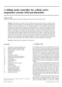
A sample design circuit can be conducted by using the circuit parameters given in Table 1 in MATLAB/Simulink. Different δ values are applied in the simulation, as shown in Figure 3c. Output voltage (Vo ) and input current (ii ) curves change accordingly, as shown in Figure 3a,b, respectively. Output voltage and input currents are zoomed; it is observed in simulations that the frequency of the ripples is equal to the SF (150 kHz). ´ Table 1. Design parameters of Modified Cuk Converter. Symbol
Quantity
Unit
Input Voltage Duty Ratio (∆) Switching Frequency Inductances (L1 , L2 , L3 ) Capacitors (C0 , C1 , C2 ) Load Resistance
15 0.1–0.9 150 100 5 100
V – kHz µH µF Ω
´ ´ The performance of the modified Cuk converter was compared to classical Cuk and buck/boost converter circuits. Figure 4a shows δ comparison of converters. A simulation platform is constructed in MATLAB/Simulink with the same parameters given in Table 1. Theoretical and simulation values of the ´ ´ modified Cuk converter validate the results. Efficiency comparison of simulated buck/boost, Cuk, and ´ ´ modified Cuk converter is depicted in Figure 4b. Modified Cuk converter efficiency is higher than classical ´ ´ Cuk and buck/boost converter. It can be stated that the proposed modified Cuk converter produces higher efficiency due to the inclusion of additional passive elements. This reduces several parasitic effects and switching/conduction losses and increases voltage gain ratio, as emphasized in [37].
Duty Ratio (∆) Switching Frequency Inductances (L1, L2, L3) Capacitors (C0, C1, C2) Load Resistance
Energies 2017, 10, 1513
0.1–0.9 150 100 5 100
– kHz μH μF Ω
5 of 14
Energies 2017, 10, 1513 Energies 2017, 10, 1513
5 of 13 5 of 13
of the modified Ćuk converter validate the results. Efficiency comparison of simulated buck/boost, of theand modified Ćuk converter validate results.inEfficiency comparison simulated buck/boost, Ćuk, modified Ćuk converter is the depicted Figure 4b. ModifiedofĆuk converter efficiency is Ćuk, and modified Ćuk converter is depicted in Figure 4b. Modified Ćuk converter efficiency is Ćuk higher than classical Ćuk and buck/boost converter. It can be stated that the proposed modified higher than classical Ćuk and buck/boost converter. It can be stated that the proposed modified Ćuk converter produces higher efficiency due to the inclusion of additional passive elements. This reduces converter produces higher efficiency due to the inclusion of additional passive elements. This reduces several parasitic effects and switching/conduction losses and increases voltage gain ratio, as ´ Figure 3. Simulation modified Cuk converter. (a) losses Outputand Voltage (V); (c) Ćuk Voltage (V); (b) (b) Input Input Current Current (A); (c)δ. δ. several parasitic effects of and switching/conduction increases voltage gain (A); ratio, as emphasized in [37]. emphasized in [37]. The performance of the modified Ćuk converter was compared to classical Ćuk and buck/boost converter circuits. Figure 4a shows δ comparison of converters. A simulation platform is constructed in MATLAB/Simulink with the same parameters given in Table 1. Theoretical and simulation values
(a) (a)
(b) (b)
Figure Ćuk, modified ĆukĆuk (a) Duty Ratio; (b) Efficiency. ´ and ´converter. Comparisonofofbuck/boost, buck/boost, Ćuk, and modified converter. (a) Ratio; (b) Figure 4. 4.Comparison buck/boost, Cuk, and modified Cuk converter. (a) Duty Duty Ratio; (b) Efficiency. Efficiency.
3. Equivalent 3. EquivalentControl Controlofof ofModified ModifiedĆuk Ćuk Converter ´ Converter 3. Equivalent Control Modified Cuk Converter A structure could be be used for for easeease of implementation to modified A cascaded cascadedPI+SMC PI+SMCcontroller controller used of implementation implementation to modified modified A cascaded PI+SMC controller structure structure could could be used for ease of to Ćuk converter as depicted in Figure 5. A simple external voltage controller can generate input current Ćuk converter as as depicted depicted in in Figure Figure 5. 5. A external voltage controller ´ Cuk converter A simple simple voltage controller can can generate generate input input current current reference, while equivalent controller controls the external input current [29,30]. reference, while equivalent controller controls the input current [29,30]. reference, while equivalent controller controls the input current [29,30].
Figure 5. Cascaded control of modified Ćuk converter. PI: proportional integral; SMC: sliding mode controller. Figure 5. ofof modified Ćuk PI: proportional integral; SMC: SMC: slidingsliding mode ´ converter. Figure 5. Cascaded Cascadedcontrol control modified Cuk converter. PI: proportional integral; controller. mode controller.
Although the modified Ćuk converter is a third-order nonlinear model, only an input current equation is required to construct anconverter equivalentiscontroller. This is the mainmodel, advantage SMC-based Although the modified Ćuk a third-order nonlinear onlyofan input current equivalent controllers, since the performance is independent of all system dynamics and equation is required to construct an equivalent controller. This is the main advantageparameter of SMC-based variations. Input currentsince of the modified Ćuk converter in termsofofallKirchhoff’s voltage law be equivalent controllers, the performance is independent system dynamics andcan parameter written in the following form:
variations. Input current of the modified Ćuk converter in terms of Kirchhoff’s voltage law can be 1 written in the following form: = ( − (1 − ) ) (12) 1
Energies 2017, 10, 1513
6 of 14
´ Although the modified Cuk converter is a third-order nonlinear model, only an input current equation is required to construct an equivalent controller. This is the main advantage of SMC-based equivalent controllers, since the performance is independent of all system dynamics and parameter ´ variations. Input current of the modified Cuk converter in terms of Kirchhoff’s voltage law can be written in the following form: di L1 1 (12) = (V − (1 − u)VC1 ) dt L1 i The terms Vi and Vc1 are input C1 voltages, and u is the switching signal of semiconductor switch as explained below. " # 1 Switch → ON Do → OFF u(t) (13) 0 Switch → OFF Do → ON The external PI controller aims to achieve the reference voltage target, and the output of the PI controller acts as reference current (i* ). The internal SMC-based equivalent current controller aims to track current trajectory, and the analytical design procedure is detailed below. The switching surface can be given as [29,30]: σ = i L1 − i∗ (14) The time derivative of the switching surface is: .
.
.
σ = i L1 − i∗
(15)
´ If the input current equation of the modified Cuk converter in (12) is written to derivative of the switching surface in Equation (15), the following equation can be obtained: .
σ=
. . Vi 1 − (1 − u)V c1 − i∗ L1 L1
(16)
.
If σ is assumed to be zero at steady-state, the equivalent control signal can be generated as given below. L . V ueq = 1 + 1 i∗ − i (17) Vc1 Vc1 .
The switching surface can be simplified as given below, considering σ is zero at steady-state. The continuous function ueq will be converted into discontinuous form as follows: .
σ = u − ueq
(18)
Closed loop control signal from switching surface can be given as: u = uˆ eq − Kσ
(19)
The term K is positive definite control gain, and if (19) is inserted in (18), the switching surface can be written as follows: . σ = uˆ eq − Kσ − ueq (20) where uˆ eq is the estimated equivalent control input. It can be written in steady-state that uˆ eq = ueq . .
σ = −Kσ
(21)
Energies 2017, 10, 1513
7 of 14
Finally, stability and existing conditions for sliding mode control must be clarified [18]. . The definition σσ < 0 must be satisfied, and it can be derived from (21) that; (
.
σ>0
σ