DHT-based Cluster Routing Protocol for IEEE802.11s mesh networks Marcos Pinheiro∗
Francisco Vasques
IDMEC, FEUP University of Porto Email:
[email protected]
IDMEC, FEUP University of Porto Email:
[email protected]
Abstract—The IEEE 802.11s draft standard defines a mesh network in which frame delivery is done by forwarding the frame through nodes, called Mesh Points (MPs). To make this possible, it specifies two routing protocols: HWMP and RA-OLSR. Both protocols suffer from scalability issues caused by the use of broadcast messages for discovery and update of routes. In this work, we propose a new routing protocol, the DHT-based Cluster Routing Protocol (DCRP), that improves the scalability of 802.11s networks. Our approach is based on two mechanisms: clustering of nodes and DHT-based searching. Clustering allows to reduce the number of broadcast messages required for routing as well as the amount of routing information broadcasted. DHT-based searching is used to make up for the required routing information that is not diffused by the DCRP itself. Some back-of-the-envelope calculations indicate that our approach increases the scalability of the routing protocol.
I. INTRODUCTION The IEEE 802.11 standards are responsible for the pervasiveness of wireless-LAN communication. Their main appeal stems from the fact that they support mobility of wireless nodes at very low cost and take advantage of the wired network infrastructure. Virtually all deployed IEEE 802.11 networks use the so-called infrastructure mode, in which a node is associated with an access point (AP) that relays all frames to and from the node. When the network has multiple APs, the communication between them is done via a wired network. The 802.11s draft standard [9] proposes to apply the Wireless Mesh Network (WMN) concept to 802.11 networks, thus allowing a wireless-only interconnection of APs, and consequently the deployment of 802.11 wireless LANs with multiple APs without any wired network infrastructure. In the terminology of 802.11s, a node may either be a mesh point (MP), which may forward frames that traverse the WMN, or a station (STA), which may receive or send frames, but does not forwards them. Furthermore, depending on the additional functionality it provides, a MP can be further classified as: a Mesh Point Portal (MPP), if it has a wired network interface, thus providing a connection to a wired network; and a Mesh Access Point (MAP), if it acts as an access point for non-mesh ∗ Marcos Pinheiro is currently on leave from DIMAp-UFRN, Brazil. His contact address at UFRN is:
[email protected]; This work was partially funded by IDMEC and by FCT/CAPES funding agencies (project SideTrail). † Silvio Sampaio is supported by FCT under project PTDC/EIA/74313/2006.
Silvio Sampaio
†
IDMEC, FEUP University of Porto Email:
[email protected]
Pedro Ferreira Souto ISR, FEUP University of Porto Email:
[email protected]
nodes, i.e. stations. A mesh point may be simultaneously a MPP and a MAP. An important issue on a WMN is message routing. In 802.11s networks, routing is performed at the data link layer and is given the name of path selection. According to the 802.11s draft standard, every MP must support the HWMP (Hybrid Wireless Mesh Protocol) [3], which is the default routing protocol. This hybrid protocol can work in both reactive and proactive modes. In reactive mode the routes are discovered on-demand. In proactive mode MPs discover the routes and constructs the route table before it is needed. However, the proactive mode is applied to routes only to the MPP, not to other MPs. The 802.11s draft standard, also specifies the RA-OLSR (Radio-Aware Optimized Link State Routing Protocol) [7] protocol, which is a proactive protocol, and may be more suitable than the HWMP in scenarios with higher mesh traffic. It should be noted that the 802.11s is rather flexible, and although it specifies only the two above mentioned protocols, it allows for the use of other path selection protocols, i.e. that are not specified in the draft document, as long as the mesh nodes agree on their use. Both the HWMP and the RA-OLSR make extensive use of broadcast messages for route discovery/update. Although, this may not be a problem for networks with up to 30 or so MPs, the size of the networks considered in the design of the 802.11s standard, it will limit the scalability of 802.11s WMNs. It is almost certain that the low cost of 802.11s WMNs and their success for smaller WMNs will tempt users to try to apply it to increasingly larger WMNs, pushing the routing protocols beyond the limits for which they were designed. In this work we propose a novel path selection protocol for IEEE 802.11s networks - the DHT-based Cluster Routing Protocol (DCRP). The main goal of the DCRP is to achieve high scalability in topologies where the mobility of the MP nodes are low or even zero, a topology that is expected to be rather popular. The proposed protocol, based on RA-OLSR, applies to wireless networks well known concepts such as clusters, distributed hash tables (DHTs) and proxies. The remaining of this paper is organized as follows. In Section II we outline the proposed protocol. A preliminary performance evaluation based on back-of-the-envelope calculations showing the scalability of the DCRP is presented in Section III. Section IV contextualizes our solution among other
978-1-4244-3938-6/09/$25.00 (c)2009 IEEE 1
works in the literature. Finally, we conclude in Section V. II. ARCHITECTURE In this section we describe the DCRP protocol. We start by describing the main components of its architecture. It follows a brief discussion about the main aspects of our approach: the DHT-based Searching Service, clustering, and the Path Selection and Forwarding processes.
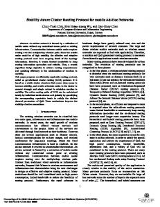
From the cluster mesh network overlay, each cluster is viewed as a Virtual Mesh Point (vMP) and each Border Mesh Point (bMP) is viewed as an interface to another vMP
{
A. Protocol Overview The DCRP protocol partitions a WMN into clusters, each of which has its own identifier. A cluster is a set of MPs physically close to each other, and the stations, i.e. non-MPs, associated with these MPs. The MPs in a cluster execute an intra-cluster routing protocol. This protocol exchanges only information regarding the routes to MPs in the cluster. This reduces the amount of routing information exchanged, because it does not include information regarding both MPs that belong to other clusters and stations in the cluster. Because the number of stations in a cluster is likely much higher than the number of MPs, this is likely to significantly reduce the number and size of routing messages broadcasted. Furthermore, this reduction will be especially effective in topologies where the MPs are mostly immobile and stations are highly mobile frequently changing the MAP with which they are associated. Thus, in intra-cluster communication, when a station sends a frame to its proxy MAP, i.e. the MAP with which it is associated, the latter has to first find the proxy MAP of the destination station. If the sender’s proxy MAP is not also the proxy MAP of the destination, the former finds the latter with the help of a DHT-based search service that we describe in the next subsection. After that, it uses the intracluster routing table, built with information collected trough the intra-cluster routing protocol, to find the next MP in the path to the destination’s proxy MAP. Subsequent MPs along that path use only the intra-cluster routing table to forward the frame towards the destination’s proxy MAP, which will finally forward the frame to its destination. In order to support communication among nodes in different clusters, the DCRP uses also an inter-cluster routing protocol. This protocol is executed only by the MPs of a cluster that are connected to MPs of other clusters. We call these MPs a cluster’s border MPs (bMP). Furthermore, we call MPs in a cluster that are connected only to MPs of the same clusters internal MPs (iMP). The inter-cluster routing protocol exchanges routing information regarding a cluster overlay network, whose nodes are the clusters of the WMN. In this overlay network, there is an edge between two nodes, if there is a wireless link between bMPs of the corresponding clusters in the underlying WMN. Figure 1 shows a WMN, its clusters and the corresponding cluster overlay network. Thus when a station sends a frame to a station in another cluster, the sender’s proxy MAP needs not only to find the destination’s proxy MAP, but also the cluster to which the destination’s proxy MAP belongs. Again, finding the cluster
Internal MP (iMP): MP, MAP, or MPP Border MP (bMP): MP, MAP, or MPP
Fig. 1.
Cluster link between bMPs
Cluster mesh network overlay.
to which a MAP belongs, is done with the help of a DHT search service. After that, the frame is forwarded towards the destination along iMPs and bMPs, using both the information in the intra-cluster routing tables and in the inter-cluster routing tables. Note that the description of the forwarding process given in this paragraph is rather simplified. In particular, the DHT is used to find not the cluster to which a MAP belongs, but a bMP of that cluster, which we call the destination station’s proxy bMP. Subsection II-D below describes the forwarding process in more detail. B. DHT-based Search Service In DCRP, MPs may use a DHT-based search service to make up for the information that is not diffused by either the intracluster or the inter-cluster routing protocol. More specifically, they use a DHT-based search service to map a station’s MAC address into the MAC address of either its proxy MAP or its proxy bMP. This DHT-based service operates at the data-link layer and uses only MAC addresses. This is in contrast with most DHTbased services which operate at the application layer and use IP addresses or even DNS names. Each register in this DHT contains the proxies associated with a station and the identifier of the cluster to which it belongs. Retrieval of this information uses a hash of the MAC address of the node as key. In order to populate the DHT, when a station associates with a MAP, the MAP enters a key-value pair in the DHT, where the key is an hash of the station’s MAC address and the value is a register with the relevant routing information for that station: the MAC addresses of the proxy MAP and the proxy bMP, and the cluster id. C. Cluster Management The reliance on clusters in the DCRP requires the provision of cluster management functionality that addresses questions like “how are clusters created?”, ”how many clusters should be created?” or ”how should they be connected?”. Although a distributed approach could be adopted, the DCRP uses currently a centralized approach. This approach is not only simpler, but it is likely to lead to better clustering decisions, as they are based on a complete knowledge of the
2
network topology. Thus, in DCRP, a special MP, the masterMP, maintains information about the network topology and takes decisions regarding clustering. When an MP joins the mesh network, it sends an RA-OLSR frame with the MAC addresses of its neighbors to the masterMP. Based on this information and on the network topology, the master-MP decides whether the joining MP should join an existing cluster, or should create a new one. D. Path Selection and Forwarding Path selection is the expression used in the 802.11s draft standard for what is usually known as routing, i.e. the process of finding the best route/path to a node. This process usually requires that routers exchange messages to build a snapshot of the network topology. Forwarding is the process of passing a packet/frame from an input interface to the appropriate output interface. This task is done by the routers using only their local information - usually obtained through the routing process. Thus the goal of path selection is to discover a valid route for forwarding. In the Internet, both functions are usually done at the network layer and the IP packet is not changed along the way. By contrast, in 802.11s mesh networks the routing is done at the data-link layer and along the way some fields of the frame may need to be changed, usually when they enter or leave the mesh network. The use of proxies proposed in this work affect the forwarding process because it may be necessary to change the address fields of a frame. 1) Path Selection: As mentioned above, in DCRP the mesh network is partitioned in clusters. Each MP knows the identifier (ID) of the cluster to which it belongs and whether it is an iMP or a bMP. Furthermore, each MP knows its neighbors and whether they belong to the same cluster or to other clusters. All this information is handed to the MP by the master-MP when it joins the mesh network. Each MP, whether an iMP or a bMP, of a cluster executes an instance of the RA-OLSR protocol, which diffuses routing information pertaining to MPs only. Most importantly, this protocol does not diffuse any information regarding stations. In addition, all the bMPs of the mesh, i.e. of all the clusters, execute another instance of the RA-OLSR protocol, in which each cluster is regarded as a virtual MP (vMP) and the bMPs of a cluster as interfaces of that vMP. This way, each bMP in the mesh is able to build a tree, according to the RA-OLSR protocol, which allows it to find a path to every other bMP in the mesh. Obviously, as this path traverses only bMPs, the path between bMPs of the same cluster must be found by that cluster’s intra-cluster routing protocol, as most likely it traverses one or more iMPs. Because a frame may traverse several iMPs when crossing a cluster, the inter-cluster instance of the RA-OLSR protocol uses not only the link quality metric specified in RA-OLSR, but also a new metric, the propagation delay, to take into account the different propagation delays of different links. The inter-cluster instance of the RA-OLSR will generate messages when there are changes to the overlay mesh network:
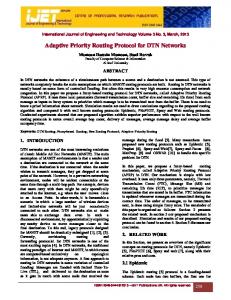
i) a new cluster is created; ii) there are changes in the bMPs of a cluster; and iii) there are changes to links between two bMPs. In addition, new messages may have to be generated when there are changes to the paths between bMPs belonging to the same cluster. Each iMP in a cluster has also a copy of the inter-cluster routing table built by the cluster’s bMPs. This copy is used to select the cluster’s bMP when forwarding a frame whose destination is in another cluster, as described below. This table is broadcasted inside the cluster periodically. The period can be adapted to reduce the negative effect of broadcasting on the cluster’s bandwidth. This is possible because the copies need not be up-to-date. Indeed, if an entry becomes stale, a MAP may select a bMP that is not the best choice, and therefore the selected bMP may then have to forward the frame to another bMP in the same cluster, leading to a longer path than if the routing table was up-to-date. However, absent any other problem, the frame will still be forwarded to its destination. 2) Forwarding: Frame forwarding with DCRP relies on the use of proxies of destination stations. In particular, DCRP uses the six-address frame format defined in 802.11s draft standard, using the Address 5 field for the destination node MAC address. The Address 3 DA field is used for the MAC address of one of the proxies of the destination node: the proxy bMP, when the frame traverses clusters different from the destination node cluster, and the proxy MAP, when the frame traverses the destination cluster. The different MPs along the path from the source to the destination use the different routing tables, i.e. both intra- and inter-cluster, and, in special cases, the DHT search service to determine the values of the different address fields of an 802.11s frame. The forwarding process with DCRP is better explained by an example. We use the example in Figure 2, which shows the path traversed by a frame that is sent by station S1 in a cluster to station S2 in another cluster, which is not a neighbor of S1’s cluster. We can distinguish six cases in forwarding along this path: forwarding by the proxy MAP of the sender’s; forwarding by an iMP that is not in the destination station cluster; egress forwarding by a bMP; ingress forwarding by a bMP, which has two distinct sub-cases depending on whether or not the bMP is in the destination station cluster; forwarding by an iMP that is in the destination station cluster; and, forwarding by the proxy MAP of the destination station. Because the last two cases do not differ from forwarding of intra-cluster frames, we describe only the first four cases in the following paragraphs. When MAP M1 receives the frame from station S1, it first looks-up the DHT to retrieve information regarding the destination station S2. As described above, it uses as key a hash of S2’s MAC address, and obtains a register containing both the MAP and the bMP proxies for S2 and the ID of the cluster to which S2 belongs. By comparing this ID with the ID of its own cluster, MAP M1 determines that S2 belongs to a different cluster. Therefore, MAP M1 sets the Address 3 DA field of the frame to the MAC address of the proxy bMP of station S2, and Address 4 SA to its own MAC address.
3
Furthermore, it sets the Address 5 and the Address 6 fields with the MAC address of the destination station S2 and of the source station S1, respectively, and flags the use of these fields by setting the AE bit. Finally, to find the next hop in the path to S2’s bMP proxy, it looks-up its own copy of the inter-cluster routing table, obtaining bMP B1. Because, MAP M1 is not directly connected to this bMP, it further looks-up the intra-cluster routing table, obtaining iMP I1. MAP M1 now sets the Address 1 RA to that iMP’s MAC address and Address 2 TA field to its own MAC address. Figure 3 (1) shows the relevant fields of the 802.11s frame sent out by MAP M1. The processing of this frame by iMP I1 illustrates the forwarding process of internal MPs in a cluster different from the destination cluster. Because the Address 3 DA field is not its own MAC address, iMP I1 determines that it is not the destination of the frame. Next it looks up the value of that field in its intra-cluster routing table. As it does not find it there, it infers that the destination is in another cluster. Therefore, to find the next hop in the path to S2’s bMP proxy, it looks-up its own copy of the inter-cluster routing table, obtaining bMP B1. Given that bMP B1 is its neighbor, it sets the Address 1 RA field to that bMP’s MAC address. Figure 3 (2) shows the relevant fields of the 802.11s frame sent out by iMP I1. The third case corresponds to egress forwarding by a bMP, i.e. forwarding by a bMP when a frame exits a cluster. This can be illustrated by the processing at bMP B1. This bMP first looks-up the value of the Address 3 DA field in its intra-cluster routing table. As it does not find it there, it then proceeds to lookup that MAC address in its inter-cluster routing table. In our example, the result is bMP B3 MAC address. Therefore, bMP B1 changes the value of the Address 1 RA to the MAC address of bMP B3. In order to avoid a new DHT lookup by S2’s proxy MAP in the case of a reply to S1, bMP B1 swaps the value of the Address 4 SA field to its own MAC address. This way, the address of S1’s proxy bMP will be learned by M2. The change of the frame’s Address 4 SA field is performed only by the egress bMP on the cluster were the frame was generated. Figure 3 (3) shows the relevant fields of the 802.11s frame sent out by bMP B1. The fourth case corresponds to ingress forwarding by a bMP, i.e. forwarding by a bMP when it receives a frame from a bMP in another cluster. There are two sub-cases two consider, depending on whether the cluster about to be entered is the destination cluster. However, ingress forwarding by a bMP that is not in the destination’s cluster is similar either to forwarding by an iMP in a cluster different from the destination’s cluster, or to egress forwarding by a bMP, in the case the bMP is simultaneously the ingress and egress bMP of the cluster being traversed. Thus the only new case is the sub-case of ingress forwarding by the bMP in the destination’s cluster. In our example this sub-case is illustrated by the processing at bMP B2. When bMP B2 receives the frame sent by bMP6, shown in Figure 3 (4), it finds out that the value of Address 3 DA field is its own MAC address. However, because the “EA flag” field is set, it has to take into account Address 5 field. As this MAC address does not belong to a station associated with
it, bMP B2 must use the DHT-based service to find the MAC address of station S2’s proxy MAP. Thus it looks-up the DHT using as key an hash of station S2 MAC address, obtaining a register which contains the MAC address of S2’s proxy MAP, MAP M2. Next it sets Address 3 DA field with that MAC address. Finally, because MAP M2 is not its neighbor, bMP B2 looks-up its intra-cluster routing to find the next hop in the route to MAP M2, obtaining the MAC address of iMP I2. Figure 3 (5) shows the relevant fields of the 802.11s frame sent by bMP B2. M1
I3 vMP1
B3
S1
I1
vMP2
vMP3 vMP5
vMP6
B1
B4
vMP4
B5
vMP10
vMP9
vMP7
vMP8
B6
B2
M2 I2 vMP11
Fig. 2.
Frame Control
Frame Control
Frame Control
Frame Control
Frame Control
Frame Control
... ... ...
... ... ...
vMP12
S2
Forwarding of a frame sent by station S1 to station S2.
Addr 1 Addr 2 Addr 3 Addr 4 SA RA TA DA
I1
M1
B2
M1
Addr 1 Addr 2 Addr 3 Addr 4 SA RA TA DA
B1
I1
B2
M1
Addr 1 Addr 2 Addr 3 Addr 4 SA RA TA DA
B3
B1
B2
B1
Addr 1 Addr 2 Addr 3 Addr 4 SA RA TA DA
B2
B6
B2
B1
Addr 1 Addr 2 Addr 3 Addr 4 SA RA TA DA
I2
B2
M2
B1
Addr 1 Addr 2 Addr 3 Addr 4 SA RA TA DA
M2
I2
M2
B1
... ... ...
... ... ... ...
AE bit
1 AE bit
1 AE bit
1 AE bit
1 AE bit
1 AE bit
1
Addr 5 Addr 6
...
(1)
S2
B1 » B3
S1 FCS
(4)
S2
B6 » B2
S1 FCS
(5)
S2
S1
Addr 5 Addr 6
...
FCS
(3)
S2
Addr 5 Addr 6
...
I1 » B1
S1
Addr 5 Addr 6
...
FCS
(2)
S2
Addr 5 Addr 6
...
M1 » I1
S1
Addr 5 Addr 6
...
FCS
B2 » I2 FCS
(6)
S2
S1
I2 » M2
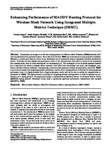
Fig. 3. Frames sent by different MPs along the path from station S1 to station S2 in Figure 2. The fields in bold are the address fields modified by the corresponding MP.
III. PRELIMINARY RESULTS In this section we present some preliminary results that show the benefits of clustering to the scalability of routing in large WMNs. More specifically, we compare the routing traffic generated by the DCRP protocol with that generated by RA-OLSR, assuming that there are no stations in the WMN. To estimate the routing traffic generated by RA-OLSR we use a model of the OLSR protocol for the ns-3 simulator. This is because, to the best of our knowledge, there is no model for 802.11s or even for RA-OLSR yet. However, because the differences between the RA-OLSR and the OLSR are not very
4
NDCRP = C × Mc + Ic × H
(1)
where C is the number of clusters, Mc is the number of TC messages sent by the OLSR protocol in a 5x5 cluster, Ic is the number of TC messages generated by a grid with as many nodes as bMPs in the mesh, and H is the average number of hops between bMPs within a cluster, i.e. the propagation delay metric. Thus the first term in Equation 1 is the total routing traffic generated by all instances of the intra-cluster routing protocol, whereas the second term is an estimation of the total routing traffic generated by the inter-cluster routing protocol. The factor H is used to take into account that the communication between bMPs in the same cluster may require more than one hop. Figure 4 compares the results obtained with the ns-3 simulation model for the OLSR protocol and those obtained with Equation 1. In computing the value of the formula we used for Mc and Ic values obtained also with the ns-3 simulation model. As for H we used the value of 5, as in our simulation we have used a 5x5 grid. As we would expect, DCRP generates a lower number of TC messages than OLSR. The results are promising, but the
90000 80000 70000 Number of Messages
relevant for the scenario we are considering, we believe that the results obtained are very close to those we would obtain, if we used a model for the RA-OLSR protocol. We plan to make more extensive experiments as soon as we get a model for the RA-OLSR protocol. To estimate the routing traffic generated by DCRP, we use a simple mathematical model with some parameters obtained with the OLSR model for the ns-3 simulator, as we describe below in more detail. The RA-OLSR protocol uses mainly two types of messages to build the routing tables: HELLO messages and TC messages. In our simulations we consider only TC messages. This is because, whereas these messages are diffused through the entire network, HELLO messages are not propagated to nodes further away than 2 hops, and thus they are not as relevant for the protocol’s scalability. The topology of the network used is a square grid of NxN nodes (MPs). The distance between neighbor nodes in the horizontal and vertical directions is 100m and constant for the entire grid. Furthermore, the radio ranges of all nodes are set so that a node can communicate in one hop only with its neighbors in the horizontal and vertical directions. As mentioned above, there are no stations. In our experiments we considered different values for N (5 to 30, in steps of 5) and run the model for 5 minutes, 5 times, for each value of N. For the analysis of DCRP, we partition the grid in clusters of 25 nodes in a square grid of 5x5 nodes, with 4 bMPs. The size of the cluster was chosen taking into account that the 802.11s draft standard was designed for meshes up to 32 MPs. Under these assumptions, the routing traffic in number of messages generated by the DCRP protocol can be estimated by:
60000 50000 40000 30000 20000 10000 0 25
100
225
400 625 Number of MAPs RA-OLSR
900
DCRP
Fig. 4. Comparison of the number of messages generated by the routing protocol.
models we used were rather approximate. Furthermore, as we stated, these experiments consider only the clustering aspect of the DCRP. The benefits of the DHT-based service have yet to be evaluated. We plan to carry out more extensive simulation studies of the DCRP to better evaluate its scalability. IV. BACKGROUND AND RELATED WORK The DCRP relies on the use of proxies, DHTs and clustering. Although these concepts have been widely applied in networks, including mesh networks, in this work we propose to use them in a integrated way, exploring their synergies, in order to obtain a more scalable routing protocol for 802.11s WMNs. The proxy concept is used both in HWMP [3] and in RA-OLSR [7] to reduce the amount of information required to route frames to non-mesh stations. In both protocols the discovery of a station’s proxy relies on broadcast messages. HWMP uses broadcast messages for route discovery, whereas RA-OLSR uses it for route announcement. Our protocol does not require broadcast messages for proxy discovery, instead it uses a DHT-based search service. Furthermore, the DCRP protocol extends the proxy concept to clusters, by means of bMP proxies. Other works that use DHT on the wireless routing process leave the task of finding the route to the DHT. In [5], [13] and [4] no additional routing protocol is needed, whereas in [11], [12] and [2] the DHT is used to determine the next node to which the frame must be forwarded. In the latter case, as this next node may not be reachable in one hop, an additional path selection protocol, e.g. HWMP, is required to discover the route to this node. In contrast with our protocol, which was designed to be easily integrated with the 802.11s standard, those protocols require the modification of the 802.11s frame, and force the use of a specific routing protocol. As illustrated above, the DCRP uses the standard 802.11s frame. Furthermore, although in our description we used RA-OLSR for both intra and inter-cluster routing, in principle DCRP can be used with other routing protocols.
5
Clustering is widely regarded as an effective approach to increase the scalability of WMNs. Several works, e.g. [6], [10] and [1], have proposed modified OLSR versions with clustering. Among other differences, a key difference between these proposals concerns inter-cluster frame forwarding. In [6], the authors propose the use of cluster headers, special nodes with multiple radios, that are able to communicate directly with neighbor cluster heads using one of their radios. By contrast, in the proposals described in [10] and [1], like in DCRP, nodes need only one radio and the transmission among neighbor clusters is done trough border nodes. However, whereas in those proposals the messages exchanged among clusters include also information about internal nodes, in DCRP the inter-cluster protocol exchanges information about border MPs only. This is possible, because of the concept of proxy bMP and the use of a DHT-based search service. As a result, we believe that DCRP generates much less inter-cluster routing traffic than the other proposals. Finally, when HWMP operates in proactive mode, all frames must pass through the root, which is usually an MPP node. Thus, the network performance degrades as the intra-mesh traffic grows. This is a severe constraint to the network scalability. In [8] the authors propose a hybrid protocol that uses HWMP in proactive mode and the Root Driven Routing (RDR) protocol together for mesh routing. However this protocol does not solve the scalability issue, as it require that the root store information about the topology of the entire network. Furthermore, every node that wishes to communicate must request the root the best route to be used. By contrast, DCRP is focused on scalability and maintains previous routes to the MPP nodes by applying a proactive protocol (RA-OLSR). However it also allows the use of other proactive protocols. V. CONCLUSION In this paper we have proposed DCRP, a novel routing protocol for IEEE 802.11s mesh networks that addresses their scalability issues by reducing the number of routing messages broadcasted. DCRP combines two well-known techniques that have been successfully applied to address similar issues in networks: clustering and DHTs. DCRP groups MPs physically close to each other in clusters. In each cluster, MPs execute an instance of a proactive routing protocol such as RAOLSR. Furthermore, a few MPs, i.e. the bMPs, of each cluster execute a mesh-wide instance of a proactive routing protocol. Clustering has two effects on broadcasting of routing information: first it reduces the scope of the broadcast of intracluster routing messages to the respective cluster, second it reduces the number and size of messages that are diffused with a mesh wide scope. Most importantly, no routing information to stations is diffused either by the inter-cluster or the intracluster instances of the routing protocols. Because stations are likely to largely outnumber MPs and also to have a higher mobility, the number and size of routing messages broadcasted by DCRP is significantly reduced. To enable forwarding of frames to stations, DCRP associates each station with two proxies MP: the proxy-MAP, i.e. the
MAP with which the station is associated, and the proxy-bMP, i.e. a bMP of the cluster to which the station belongs. The latter is used for forwarding inter-cluster traffic, whereas the former is used for forwarding inside the cluster of the destination station. The proxy-MPs of each station are stored in a DHT based search service and they can be retrieved using as key a hash of the station’s MAC address. Because DHTs support searches in flat name-spaces in O(log N ), where N is the number of nodes in the DHT, retrieval of the proxy-MPs of a station in DCRP is rather efficient, The results of a preliminary analysis of the number of routing messages transmitted based on simulations and a simple mathematical model are promising. However, this analysis focused only on the effectiveness of clustering and used a model for OLSR rather than RA-OLSR. We are now working on a more comprehensive performance analysis not only in terms of metrics, e.g. evaluating also the end-to-end delay and the number of lost frames, but also in terms of models analyzed, e.g. a more complete model of DCRP including the effects of both clustering and DHT. Furthermore, we plan to compare DCRP with both HWMP and other proposals to increase the scalability of 802.11s. R EFERENCES [1] E. Baccelli. OLSR Scaling with Hierarchical Routing and Dynamic Tree Clustering. In IASTED International Conference on Networks and Communication Systems (NCS),(Chiang Mai, Thailand), 2006. [2] E. Baccelli and J. Schiller. Towards scalable manets. ITS Telecommunications, 2008. ITST 2008. 8th International Conference on, pages 133–138, Oct. 2008. [3] Michael Bahr. Update on the hybrid wireless mesh protocol of ieee 802.11s. 2007 IEEE Internatonal Conference on Mobile Adhoc and Sensor Systems, MASS, pages 4428721 –, 2007. [4] Matthew Caesar, Miguel Castro, Edmund B. Nightingale, Greg O Shea, and Antony Rowstron. Virtual ring routing: Network routing inspired by dhts. Computer Communication Review, 36(4):351 – 362, 2006. [5] T. Fuhrmann, P. Di, K. Kutzner, and C. Cramer. Pushing Chord Into the Underlay Scalable Routing for Hybrid MANETs. Univ., Fak. f¨ur Informatik, Bibl., 2006. [6] Y. Ge, L. Lamont, and L. Villasenor. Hierarchical OLSR-a scalable proactive routing protocol for heterogeneous ad hoc networks. In IEEE International Conference on Wireless And Mobile Computing, Networking And Communications, 2005.(WiMob 2005), volume 3, 2005. [7] Guido R. Hiertz, Sebastian Max, Zhao Rui, Dee Denteneer, and Lars Berlemann. Principles of ieee 802.11s. Proceedings - International Conference on Computer Communications and Networks, ICCCN, pages 1002 – 1007, 2007. [8] A.O. Lim, X. Wang, Y. Kado, and B. Zhang. A hybrid centralized routing protocol for 802.11 s WMNs. Mobile Networks and Applications, 13(1):117–131, 2008. [9] IEEE P802.11s/D1.10. Draft amendment to standard ieee 802.11: Ess mesh networking. March 2008. [10] F.J. Ros and P.M. Ruiz. Cluster-based OLSR extensions to reduce control overhead in mobile ad hoc networks. In Proceedings of the 2007 international conference on Wireless communications and mobile computing, pages 202–207. ACM New York, NY, USA, 2007. [11] K. Takeshita, M. Sasabe, and H. Nakano. Mobile p2p networks for highly dynamic environments. Pervasive Computing and Communications, 2008. PerCom 2008. Sixth Annual IEEE International Conference on, pages 453–457, March 2008. [12] T. Zahn and J. Schiller. MADPastry: A DHT Substrate for Practicably Sized MANETs. In Proc. of ASWN, 2005. [13] Thomas Zahn and Jochen Schiller. Dht-based unicast for mobile ad hoc networks. Proceedings - Fourth Annual IEEE International Conference on Pervasive Computing and Communications Workshops, PerCom Workshops 2006, 2006:179 – 183, 2006.
6