Distributed or Centralized Mobility? Philippe Bertin, Servane Bonjour
Jean-Marie Bonnin
Orange Labs Cesson-Sévigné, France {firstname.name}@orange-ftgroup.com
TELECOM Bretagne Cesson-Sévigné, France
[email protected]
Abstract—Expecting a significant increase in number of mobile terminals to be managed together with a mobile data traffic boom in future heterogeneous networks, current centralized mobility management schemes may encounter scalability issues due to the creation of network bottlenecks and single point of failures. Recently, alternative approaches have been proposed to better distribute mobility management entities not only in the control plane but also in the data one like the “Dynamic Mobility Anchoring” scheme we designed. In this article we compare centralized and distributed approaches and describe our simulation environment using TCP in both schemes. The obtained results validate the adequacy and design of “Dynamic Mobility Anchoring”. They confirm that we may expect interesting benefits in terms of handover latency and global scalability when moving towards such a distributed mobility management in future networks. Mobility, DMA, Mobile IP, Distributed Mobility
I.
INTRODUCTION
When evolving towards future network generations, expectations are high in terms of providing the end user with "always on" services in a fully converged framework where fixed/mobile or wireless/wireline/optical networking boundaries are definitely broken. The main future networking paradigms will focus on simplicity and agility allowing the delivery of any kind of traffic whatever the user's location and its terminal(s) capacity are. This shall be realized using, opportunistically, the different access network resources that can be provided by heterogeneous technologies in different areas. Heterogeneous networks' agility will become a key property for mobility management schemes in addition to handover efficiency, optimized traffic forwarding and signaling delays. Current mobility management schemes standardized for IP and cellular networks are mainly centralized and hierarchical, which leads to well known bottlenecks and single point of failure issues when traffic increases significantly. Alternative schemes distributing mobility management control and data path functions can be seen as promising approaches for improving network agility in terms of mobility support. Evaluating their real benefit requires additional studies and evaluation comparison. In this article, we present a deep analysis of centralized and distributed mobility management approaches enforced with comparative simulations. The simulation model allows us to properly design the new DMA (Dynamic Mobility Anchoring) scheme and compare its performances to optimized IP based centralized approaches. Further to support comparative analysis, our simulation model
validates the adequacy of DMA to provide mobility support in typical mobile data transfers scenarios. In section II we introduce mobility management approaches by mentioning well known centralised schemes and recent distributed schemes; in section III we provide a qualitative comparison between centralised and distributed mobility approaches; in section IV we introduce our simulation model and analyse the simulation results for TCP based traffic validating the DMA scheme and highlighting the brought benefits. II.
MOBILITY MANAGEMENT APPROACHES
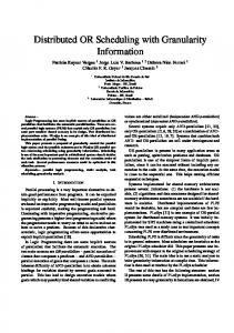
A. Mobility in Cellular Networks Mobility management functions in cellular systems have been designed to adapt to different mobility situations. A main example is the 3GPP architecture which provides different mobility schemes either within a given 3GPP radio access network or between distinct 3GPP radio access networks, or even with non 3GPP based access networks. The main functional entities, necessary to support packet based access and mobility in 3GPP networks, are outlined on Fig. 1: integration of 2G and 3G cellular technologies rely on a common IP core network based on SGSN (Serving GPRS Support Node) and GGSN (Gateway GPRS Support Node) nodes; interworking with non-3GPP networks can be realized either through GANC (Generic Access Network Controller) or PDG (Packet Data Gateway). These are specific interworking gateways used for tunneling cellular traffic and signaling over the IP based non 3GPP network. When evolving towards the Evolved Packet System, a new access network known as the "Evolved UTRAN" or LTE (Long Term Evolution) is introduced, together with new packet core network entities, the Serving Gateway and PDN (Packet Data Network) Gateway [1][2]. The Mobile Node's (MN) data path is established through tunnels between access and core network entities: it is mainly based on GTP (GPRS Tunneling Protocol). For example, in LTE, MN's traffic is encapsulated in a GTP tunnel between the eNodeB and the Serving Gateway, as well as in another between the Serving and PDN Gateways, see Fig. 2. Hence, whereas LTE's control plane is well distributed, the data plane itself remains highly centralized and hierarchically organized. B. Mobility in IP based networks From Mobile IPv4 [3] and Mobile IPv6 [4] protocols to recent Proxy Mobile IPv6 [5], IETF standards support different
978-1-4244-4148-8/09/$25.00 ©2009 This full text paper was peer reviewed at the direction of IEEE Communications Society subject matter experts for publication in the IEEE "GLOBECOM" 2009 proceedings.
IMS, Internet…
PDN Gateway
GGSN SGSN 2G SGSN 3G GANC
S- GW
Glossary IMS: IP Multimedia Subsystem GGSN: Gateway GPRS Support Node SGSN: Serving GPRS Support Node PDN: Packet Data Network S-GW : Serving Gateway PDG: Packet Data Gateway GAN: Generic Access Network GERAN: GSM-Edge Radio Access Network UTRAN: UMTS Access Network RNC: Radio Network Conroller BTS: Base Transceiver Station PDG
BSC
GAN
GERAN
RNC
RNC
evolved UTRAN
UTRAN
BTS
Non 3GPP networks (WLAN, WiiMAX …)
eNodes B NodeB
Fig. 1. overview of 3GPP architecture (user plane, packet services domain)
mobility solutions. Those protocols may be simply deployed in "full IP" based networks or integrated as building pieces of cellular architectures designed by other standardization bodies (3GPP, 3GPP2, Wimax Forum…). Most approaches are derived from Mobile IP (MIP) principles, implementing a centralized approach where end user data traffic is encapsulated between a centralized mobility entity (the Home Agent (HA) in MIP or the Local Mobility Agent (LMA) in PMIPv6) and the MN or intermediate nodes such as the Mobile Access Gateway (MAG) in PMIPv6, the Foreign Agent (FA) in Mobile IPv4, the Access Router (AR) in FMIPv6 [6] or the Mobility Anchor Point (MAP) in HMIPv6 [7]. MIPv6 and PMIPv6 tunneling principles are depicted together with 3G LTE ones on Fig. 2. C. Towards new distributed Mobility schemes? As mentioned above, both cellular and IP based mobility schemes use a centralized (and eventually hierarchical) construction of tunnels to maintain the data path to MN's location. Such a data path is then realized using one or several encapsulation levels, even when the MN is motionless. During
Fig. 2. Data path tunneling in LTE, PMIPv6 and Mobile IPv6 networks
handovers, tunnel updates in the core network may impact on the overall efficiency by introducing delays and packet loss. Optimizations envisage direct forwarding of data traffic between neighbors' access nodes during handover procedures with the counterpart of adding an encapsulation function and introducing out of sequenced packets delivery risk. For example, both LTE and FMIPv6 handover procedures use a temporary tunnel between the old and the new access nodes (eNodeB in LTE and AR in FMIPv6) for packet forwarding until handover completion. Considering that centralized encapsulation and data path management create issues such as network bottlenecks and single point of failures, new distributed approaches may be envisaged for mobility management schemes, applicable either to intra-technology or to inter technology mobility. Hence, a distributed approach for 3G SAE core network has been proposed in [8] distributing a MIP HA function between several Mobility Agents and using a DHT (Distributed Hash Table) structure to maintain binding caches. Considering that the mobility path should benefit from being managed and anchored as close as possible to the MN, avoiding the use of specific core network functions, we proposed in [9] a new distributed and dynamic mobility scheme, now named DMA. Our approach is further considered throughout the rest of this paper. The DMA scheme is fully distributed among access nodes, see Fig. 3 for an example of a MN's data path evolution. Instead of applying a single mobility path per MN, mobility anchoring is realized for each traffic flow. When setup, a traffic flow is implicitly anchored at the Access Node (AN) the MN is attached to. This anchor function is responsible for maintaining the traffic flow data path towards the MN when it moves out of current AN radio coverage by setting up a simple tunnel between flow's anchor AN and MN's current AN. Above ANs, standard IPv6 routing is performed without using centralized tunnel schemes. Hence, until the MN moves away from a flow's anchor AN, no tunneling functions need to be activated for this given flow and all the corresponding traffic is routed using standards IP mechanisms as for any "fixed" node. Given the fact that a huge percentage of mobile applications are set up
978-1-4244-4148-8/09/$25.00 ©2009 This full text paper was peer reviewed at the direction of IEEE Communications Society subject matter experts for publication in the IEEE "GLOBECOM" 2009 proceedings.
Fig. 3. Data path evolution in DMA. In (1) the MN has one active flow anchored on its current AN. Following a handover, the data flow in (2) is tunneled between its anchor and the new AN to which the MN is attached. A new flow is initiated in (3), anchored on the current AN. The first flow anchoring is sustained until the flow ends up (4), then the corresponding inter- AN tunnel is closed.
while the user's remains stationary on the one hand and that most of transport and application sessions have a short lifetime (e.g. TCP connection for SMTP or HTTP sessions) on the other one, the DMA scheme's benefits may be huge in terms of resources utilization in access and core networks. It also ambitions to eliminate most single point of failures and bottleneck issues caused by mobility management. DMA can also be used in heterogeneous networks environment where the different ANs provide different radio interfaces technologies. Such emerging schemes are not yet mature; we need to validate those new concepts, evaluate their efficiency and compare them to more traditional approaches III.
CENTRALIZED VS DISTRIBUTED MOBILITY MANAGEMENT
In this section we further compare centralized and distributed mobility management approaches, focusing on data path encapsulation and handover schemes. A. Encapsulation in data path Centralized schemes require the management of either one or several hierarchical tunnels, in order to maintain the data path between a central network entity and the MN. A single data path is maintained per MN, unifying the way its different traffic flows and sessions are routed. Because of the simplicity to deploy such tunnels, they are very well mastered and broadly used. However, those tunnels introduce data overhead due to the necessary encapsulations, as well as data processing at their end-points to perform encapsulations/de-capsulation functions. Tunnels ciphering and header compression options may also add further processing. The induced overhead may impact, not only well dimensioned core network links, but also access networks and possibly wireless links. In wide area networks, central entities (HA in MIP and PDN Gateway in LTE) need to maintain a considerable number of per-user tunneling contexts, in the range of millions for a nationwide network, which may cause scalability issues. The aggregated traffic is also huge and will grow exponentially as the expected mobile data traffic explosion will appear. Data path centralization introduces well known single point of failure and bottleneck issues that cannot be solved without costly dimensioning and redundancy engineering.
On the other hand, in distributed schemes, temporary tunnels are envisaged between access nodes only when necessary, i.e. consecutive to handovers. When the MN does not move, its data traffic can be simply routed without requiring additional overhead. With network tunnels' endpoints being located at access nodes' level, the rest of the network is not impacted. This should reduce the necessary overhead and encapsulation processing per a large factor compared to centralized schemes. However, per user contexts may need to be maintained in each anchor: an active user may have parallel data flows anchored at several different access nodes. The resultant number of contexts is slightly higher than for centralized schemes but those contexts are distributed among access nodes, avoiding scalability issues. In a nationwide network with thousands of base stations, the maximum number of contexts per equipment would then be in the order of a thousand, much lower than the millions of contexts estimated in a centralized scheme. Considering that in DMA for example, only a sub-number of MNs contexts necessitate a tunnel maintenance (counter to a centralized scheme), it appears feasible to distribute them among ANs. Hence, single point of failure and bottleneck issues should be eliminated or isolated in e.g. an overloaded access node. B. Handover schemes In centralized schemes, handovers require forwarding updates accordingly to tunnel end points movement. Main advantages are the simplicity and maturity of such well-known, widely spread approaches. Handover and location update signaling is generally unique for a given terminal, independently from the number of active application sessions (it need to be noted however than in 3GPP networks several GTP contexts may be activated by a single MN, multiplying signaling updates for each mobility event). Hierarchical handovers facilitate the development of interworking schemes between different types of networks and access technologies. Latency induced by handovers may however be quite important: they depend on the type of handover (intra or inter access gateways), the load and capacity of tunnel end-points and the underlying network latency. Optional traffic forwarding between neighbors' access nodes during handovers restricts packet loss and delays. It may however create out of sequence packets delivery due to the use of two distinct forwarding paths during the handover procedure, which leads to transport protocols efficiency issues when using TCP for instance, see [10]. Distributed schemes are expected to provide fast path updates during handovers, especially when the target AN is close to the anchor node. Out of sequence packets delivery can be avoided by using only one data forwarding point per flow, its anchor AN. Handover and location signaling only involve the AN level. They may however require several parallel updates when the flows of a moving MN are anchored on different ANs. Delays and packet loss may be impacted by the distance between the old and the new AN, favoring short applications or nomadic situations. Heterogeneous networks environments can be provided towards ANs of different access technology distributed in the same network (e.g. operated by a given operator). However, interworking between different
978-1-4244-4148-8/09/$25.00 ©2009 This full text paper was peer reviewed at the direction of IEEE Communications Society subject matter experts for publication in the IEEE "GLOBECOM" 2009 proceedings.
providers’ networks supporting either the same or different technologies need more investigations in elaborating the different scenarios where direct tunneling between access nodes could be allowed or not. A hierarchical approach may be still envisaged between different distributed schemes, in access and core networks for instance. C. Comparison outcomes The main pros and cons of centralized and distributed schemes are summarized in Table I. Interesting benefits could be expected with distributed mobility schemes, which requires to be confirmed and validated through simulations. IV.
SIMULATION OF CENTRALISED AND DISTRIBUTED MOBILITY
A. Simulation environment Our simulation environment is based on the OPNET simulator [11], it simulates an IPv6 and IEEE 802.11b based Wireless LAN, alternatively implementing a centralized and a distributed mobility scheme. Our centralized scheme is based on MIP but incorporates handover optimizations. Our distributed scheme implements the DMA approach; it anchors traffic flows on ANs depending on the IP address used to establish the flow. Both approaches implement link layer triggers to initiate layer 3 handover as soon as possible when a radio handover happens. For further future optimizations, we envision to implement a "make before break" mechanism. Handover procedures are as follows: on receipt of the radio link layer trigger, the MN IP layer initiates immediately a Router Solicitation message in MIP or uplink traffic to its TABLE I.
encapsulation
tunnels' management
user's context
handover
Inter-network mobility
PROS & CONS OF CENTRALISED AND DISTRIBUTED MOBILITY Centralised schemes
Distributed schemes
+ single path per MN + mature - permanent tunnel(s) per active MN - overhead, processing + easy to deploy - huge aggregated traffic in network endpoints - bottlenecks/single point of failures issues - may use multiple tunnels context per MN + easy to administrate - dimensioning of central mobility agents, scalability + well known / wide spread mature schemes + simplicity - handover delays - packet de-sequencing risk when inter-AN forwarding is used + "easy" thanks to centralization & hierarchy
+ no tunnel when the active MN is motionless + avoid unnecessary overhead + temporary tunnels endpoints distributed at the AN level + avoid bottlenecks / single point of failures - multiple inter AN tunnels per MN situations + avoid scalability issues - contexts replication (e.g. for a MN having flows on different anchors) + fast path update between AN + single path per flow - parallel updates of MN's anchors - delays dependent from inter-ANs distance (hops) +- may re-introduce hierarchies - need further investigations
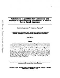
different anchors in DMA (such traffic being used for location contexts and tunnels updates). In the MIP approach, the AN being the first access router on MN's link, it answers immediately to Router Solicitation by advertising its prefix and related information. The MN performs stateless auto configuration to obtain a new IPv6 address and initiates its Binding Update towards the HA. At Binding Acknowledgement reception, MIP based handover is completed. In the DMA approach, the current AN tunnels uplink traffic towards the respective anchor(s) node(s), which update location and tunneling contexts completing the DMA handover procedure. In order to optimize the MIP based centralized scheme, we eliminate the usual delays in sending Router Solicitation and Router Advertisements; we also use an optimistic Duplicate Address Detection (DAD) [12] procedure, avoiding the additional delays caused when verifying address uniqueness before initiating the Binding Update procedure. In DMA, the new address autoconfiguration can be performed in parallel to the handover procedure as it does not impact on it. Both DMA and MIP may also use a statefull autoconfiguration but, when MIP is used, this would introduce additional delays. For both schemes we also implement the necessary recovery timers for retransmission of location update traffic when needed, following packet loss or corruption due to bad radio quality for instance. Our simulated network is composed of 13 access nodes providing a dense coverage area of 13 radio cells, see Fig. 4. 11 Mobile Node's are moving at a pedestrian speed of 1m.s-1 following random waypoint mobility models during 17 minutes. The WLAN handover algorithm is optimized for performing scanning and cell re-selection in advance to access point coverage loss, leading to very efficient radio handover latency of less than 1ms in very good radio environments.
Fig. 4. Simulation scenario. 11 MNs are moving within 13 radio cells managed by independent ANs. Either MIP or DMA mobility is used. In the MIP scenario, the HA is connected to the gateway, ensuring optimal performances. A FTP server, reachable through IP, is located outside of the access network.
978-1-4244-4148-8/09/$25.00 ©2009 This full text paper was peer reviewed at the direction of IEEE Communications Society subject matter experts for publication in the IEEE "GLOBECOM" 2009 proceedings.
Access nodes are directly connected to a border router. For the MIP based scheme, the HA is integrated within the access network and connected to the border router. Its performances become hence similar to what can be expected with a localized mobility management such as Proxy Mobile IPv6. A FTP server is located outside of the access network. Hence, both DMA and MIP schemes are well optimized and deployed in a similar way in order to obtain results that can be easily compared. In a wider area scenario, the HA should be located away from the access network implying additional delays for the centralized scheme. Each MN initiates an FTP connection with the server every 256 sec., downloads a 3MB file and closes the connection. We use the NewReno TCP version with Selective ACK and receive buffers of 8KB in MN and 32 KB in FTP server. Other TCP parameters are tuned to be as close as possible to existing mobile terminals’ implementations. B. Simulation results During our simulation time, 44 TCP connections are launched: each MN initiates 4 TCP connections, each consisting of an FTP file download. At the end of the simulation time, not all connections are resumed: only 31 are completed in the MIP case and 32 in the DMA one, which indicates slightly better performances for DMA, as files' downloads are less delayed. Globally, 155 handovers occur in each scenario. In the MIP case, 1 context is maintained in the HA per MN, leading to handle permanently 11 active contexts and corresponding tunnels. In the DMA case, per MN contexts are dynamically distributed among anchor ANs: a maximum of 27 simultaneous contexts are reached with a mean rate of 18 active contexts distributed between the ANs, each AN managing simultaneously 0 to 4 session contexts. Thus, if DMA globally necessitates the management of more contexts that MIP, the resulting distribution seems to be efficient as it minimizes the number of contexts managed in each AN. Looking at FTP download time, table II confirms that DMA slightly outperforms MIP with a mean gain of about 3%. Differences are mainly due to the avoidance of tunneling as long as the MN is associated to a flow's anchor AN. These results would have been even better for DMA in scenarios considering either motionless users or shorter files' downloads. a) Handover latency In terms of handover latency, the results outline the performance gain in DMA, see table III. Handover latency measurement includes both layer 2 (WLAN) re-association and layer 3 (MIP and DMA) updates. The mean handover latency is 8 times lower in DMA (411 ms vs 3.4 sec for MIP) with a better but important standard deviation (1.4 vs 4.1 for MIP). Differences are mainly due to the address autoconfiguration in
TABLE III.
Min. Max. Mean Std. Dev.
Min. Max. Mean Std. Dev.
Optimized MIP (sec.)
DMA (sec.)
0.006 15.364 3.403 4.163
0.002 11.743 0.411 1.400
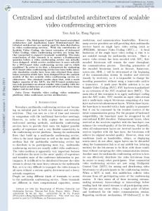
MIP but also to the round trip time for MN to HA bindings. In a wider area network, this binding delay would be further increased because of the distance between the ANs and the centralized HA. Our random trajectory model involves handovers happening in very different situations, where packet loss may be important. Combined with potential radio coverage and interference issues, these trajectories explain the high differences between the different achieved handover latencies. b) TCP results The suite of TCP segments numbers received by a given MN in both DMA and MIP schemes are shown on Fig. 5 (other MNs show similar behaviors). 4 TCP connections are initiated sequentially, each of them consisting in the reception of 3000000 TCP segments. The different curves show some periods where TCP segments progression are slow down because of handovers. In the MIP case, TCP segment progress is slightly more impacted than in the DMA case, resulting in an increase of the overall transfer delay. This confirms the overall FTP performances presented above. Depending on MN service interruption time during handover, TCP algorithms such as congestion avoidance and slow start may be triggered, decreasing the overall transfer delay. The analysis of TCP segment delays shows a better performance for DMA than for MIP as depicted on Table IV and Fig. 5. The obtained values are quite close in both schemes (305 and 307 msec for DMA and MIP schemes respectively), however the repartition depicted in Fig. 6 outlines that DMA delays are slightly better than MIP ones. The HA being directly connected to the gateway router similarly to any AN, MIP based delays are very well optimized; both DMA and MIP tunnels are also of similar "lengths". Hence, the achieved differences are mostly due to TCP segments received for connections being anchored on a current MN's AN in DMA avoiding inter AN tunneling delays. Lastly, the evolution in terms of the sum of observed TCP retransmissions is depicted on Fig. 7. DMA and MIP follow a similar curve, resulting however in about 20% more retransmissions for MIP.
TABLE IV. TABLE II.
HANDOVER LATENCY
TCP SEGMENT DELAYS COMPARISON
FTP DOWNLOAD TIME
Optimized MIP (sec.)
DMA (sec.)
237.697 433.062 294.723 46.761
235.360 428.392 285.283 48.295
Min. Max. Mean Std. Dev.
Optimized MIP (sec.)
DMA (sec.)
0.3025 0.313 0.307 0.001
0.3019 0.311 0.305 0.001
978-1-4244-4148-8/09/$25.00 ©2009 This full text paper was peer reviewed at the direction of IEEE Communications Society subject matter experts for publication in the IEEE "GLOBECOM" 2009 proceedings.
3500000 3000000 DMA-1
TCP segment
2500000
MIP-1 DMA-2
2000000
MIP-2 DMA-3
1500000
MIP-3 DMA-4
1000000
MIP-4
500000
989
949
908
867
826
785
745
704
663
622
581
541
500
459
418
377
337
296
255
214
173
133
51
91.8
10.2
0
time
Fig. 5. TCP segments number evolution. The MN initiates 4 FTP transfers, resulting in 4 different TCP connections. TCP segments are numbered from 0 to 3000000 for analysis simplicity reason. The figure compares received TCP segments progress in DMA and MIP. 0.314
TCP segment delay
0.312 0.31 0.308
DMA MIP
0.306 0.304 0.302 0.3 0
200
400
600
800
1000
time
Fig. 6. TCP segment delay, considering all MNs (11). 1000
of 10th of msec.. Delays in distributed schemes are sensitive to the underlying backbone network capacity and topology: ANs will not achieve similar forwarding performances in a star based or a ring based topology. Our simulation scenario implements a simple star based topology where each AN has a point to point link with the gateway leading to homogeneous inter-AN tunnel delays. In a wide area access network either ring based or hierarchical star based topologies would have led to achieving various inter AN delays dependent of ANs locations. Anyway, globally it can be expected that mean interAN delays should be lower than in our simple star topology. Lastly, the AN complexity itself is kept reasonable: only some contexts, tunnels and forwarding policies are added to standard access router functions. V.
CONCLUSION
Our comparison and simulations outline the simplification and gain that can be expected with the dynamic use of distributed mobility contexts and tunnels. They also serve as a first proof of concept for disruptive distributed mobility management well adapted to flat network architectures. Adaptation of the mobility management scheme to MN's dynamic and heterogeneous radio environment is key to achieving scalability in wide scale mobility and high data traffic expectations support in next generations' networks where every host can become mobile at any time. In our future work we will carry on further simulation and analytical comparison between distributed and centralized mobility management at a nationwide network scale, deeper investigating the support of heterogeneous access technologies.
900
REFERENCES
TCP retransmission
800 700
[1]
600 DMA
500
MIP
400 300 200 100 979
938
898
857
816
775
734
694
653
612
571
530
490
449
408
367
326
286
245
204
163
122
81.6
0
40.8
0
tme
Fig. 7. Cumulative TCP retransmission count considering the 44 TCP connections distributed between the 11 MNs.
Our simulation model is the first one incorporating a fully distributed approach such as DMA. It allows supporting DMA design, validation and comparison to legacy centralized schemes. The obtained results confirm the expected benefit . If globally more contexts need to be handled, their distribution between ANs avoids maintaining a central mobility manager network entity that could imply bottlenecks and single point of failure issues. Achievements in terms of handover latency and TCP delay are better optimized in DMA thanks to the avoidance of tunneling processing and transfer delays when active flows are anchored on the current AN. TCP end to end mechanisms are thus less sensitive to DMA than to MIP even if our simulation scenario is well optimized for MIP based approach. Traffic delays would then be more impacted in a centralized nationwide network where the HA is implemented in core network platforms increasing RTT delays in the order
Lescuyer, P.; Lucidarme T., "EVOLVED PACKET SYSTEM (EPS) The LTE and SAE Evolution of 3G UMTS", John Wiley & Sons. 2008. [2] Ali, I. et al., "Network-based mobility management in the evolved 3GPP core network," Communications Magazine, IEEE , vol.47, no.2, pp.5866, February 2009 [3] C. Perkins, "IP Mobility Support for IPv4", RFC 3220, Jan. 2002. IETF; [4] D. Johnson, C. Perkins, and J. Arkko. "IP Mobility Support in IPv6", RFC 3775, June 2004. IETF. [5] S. Gundavelli & al., "Proxy Mobile IPv6", RFC 5213, August 2008. IETF. [6] R. Koodli. "Fast Handoffs for Mobile IPv6", RFC 4068, July 2005. IETF. [7] H. Soliman & al., "Hierarchical Mobile IPv6 Mobility Management (HMIPv6)", RFC 4140, August 2005. IETF. [8] Fischer, M.; Andersen, F.-U.; Kopsel, A.; Schafer, G.; Schlager, M., "A Distributed IP Mobility Approach for 3G SAE," IEEE 19th International Symposium on Personal, Indoor and Mobile Radio Communications, 2008. PIMRC 2008. [9] Bertin, P.; Servane Bonjour; Bonnin, J.-M., "A Distributed Dynamic Mobility Management Scheme Designed for Flat IP Architectures," New Technologies, Mobility and Security, 2008. NTMS '08. [10] Rewaskar, S.; Kaur, J.; Donelson Smith, F., "A Passive State-Machine Approach for Accurate Analysis of TCP Out-of-Sequence Segments", ACM SIGCOMM Computer Communication Review vol 36, no 3, July 2006 [11] OPNET modeller, http://www.opnet.com/ [12] N. Moore. "Optimistic Duplicate Address Detection (DAD) for IPv6", RFC 4429, April 2006. IETF.
978-1-4244-4148-8/09/$25.00 ©2009 This full text paper was peer reviewed at the direction of IEEE Communications Society subject matter experts for publication in the IEEE "GLOBECOM" 2009 proceedings.