MATEC Web of Conferences 225, 02022 (2018) https://doi.org/10.1051/matecconf/201822502022 UTP-UMP-VIT SES 2018
Dynamic inverse controller with Matrix Converter Drive Feed Three Phase Induction Motor Settar S Keream1,2, Ahmed N Abdalla1,* , Mohd Razali Bin Daud3 and Johnny Koh4 1Faculty
of Engineering Technology, University Malaysia Pahang, Malaysia. of Engineering, University of Anbar, Iraq. 3Faculty of Electrical Engineering, University Malaysia Pahang, Malaysia. 4Department of Electronics and Communication Engineering, Universiti Tenaga Nasional, Malaysia 2College
Abstract. Dynamic inversion (DI) is a controller technique by which existing undesirable dynamics are cancelled out and changed by desirable dynamics. The application of induction motor drives with sinusoidal input currents a matrix converter combined with DI is used which directly connects a three-phase input voltage source to a three-phase (AC-AC converter) without dc-link components. This paper presents a novelty of using nonlinear dynamic inverse controller with matrix converter topologies on three phase induction motor. The efficiency of the converter and their modulation techniques for the implementation of the strategies is increased. The speed response tracking and torque ripple minimization is achieved. The robustness of the proposed method has been confirmed from simulation and experimental model.
1 Introduction Induction motor was the most commonly used in industrial applications because it has a remarkably simple, cheap, highly reliable and robust construction. Dynamic inversion is a controller method by which undesirable dynamics are negated out and changed by required dynamics. This termination and replacement is skilled by cautious algebraic choice of the feedback function. It is for this reason the part of DI methodology is called feedback linearization. It applies to both SISO and MIMO systems, if that the control effectiveness function (in the SISO case) or the control influence matrix (in the MIMO case) is invertible [1]. This method applied for both output feedback (input-output feedback linearization), fullstate feedback (input-state feedback linearization). A central assumption in this method is the plant dynamics are perfectly modelled, and then can be negated closely. In practice this theory is not naturalistic, and hence the new dynamics need some sort of robust controller [2] and [3]. The operations of the induction motor drives have continuous to improve, the research improvements in recent years have been focused on improving interface with the function to afford clean power distribution scheme. The using of MC input voltages with changed values to decrease the inherent torque ripple that appears when direct torque control (DTC) was used to drive induction motor had *
Corresponding author:
[email protected]
© The Authors, published by EDP Sciences. This is an open access article distributed under the terms of the Creative Commons Attribution License 4.0 (http://creativecommons.org/licenses/by/4.0/).
MATEC Web of Conferences 225, 02022 (2018) https://doi.org/10.1051/matecconf/201822502022 UTP-UMP-VIT SES 2018
been illustrated by [4] and [5]. It was improved the ratio of transfer voltage is increased from 50% to 86.6% by using MC compared by the conventional DTC with MCs at the expense. [6] and [7] proposed indirect matrix converters with four step switching in rectifier bridge to reduce the electromagnetic torque ripple which looks when direct torque control method was used in induction motors. The simulation results of DTC were based on indirect matrix converters (IMC) and the evaluation of motor performance under the suggested control scheme with respect to those were gotten under conventional DTC confirms its effectiveness and accuracy. Using Matrix Converter rather than voltage source inverter for a high-performance process providing in Direct Torque Control (DTC) have been observed by [8]; [9] . [10] showed the using of matrix converters voltage vectors to minimize the ripple torque which was one of the greatest significant problems for induction motors with direct torque control expending matrix converters. The simulation results demonstrated the effectiveness of A hybrid strategy for current control of an induction motor, fed from a matrix converter has suggested by [11, 12]. This strategy was fundamentally a mixture of Hysteresis Current Controller (HCC) and SVM method. The effectiveness of the method was verified by simulation reliability of the semiconductor constructions, the matrix converter topology is suggested for dangerous temperatures and critical volume/weight applications. In this paper, a performance analysis of the dynamic inverse controller with matrix converter topologies and their combined connections were presented. The conservative control scheme for the rectifier stage in the indirect matrix converter was studied and its space vector diagram was derived. The paper also focuses on analysis and developing the control algorithm of the NDI with matrix converter topologies. The simulation and practical results were provided to validate the analyzed system. It has proven to be an easy way of controlling nonlinear systems. Next to this, it offers possibilities for very robust control through an expansion called incremental nonlinear dynamic inversion.
2 THEORETICAL BACKGROUND 2.1 Dynamic Inverse DI, a controller synthesis technique, can cancel and replace undesirable dynamics or existing deficient to designer-specified desirable dynamics. Cancellation and replacement are achieved by elaborative selected algebra of a feedback function [13]. It is assumed in this approach that the plant dynamics are modeled to the perfect level, and thus the feedback functions can precisely cancel it. However, this assumption is not practically realistic; Ascribed to plant uncertainties, it is needed for the DI controller that some degree of robustness to inhibit undesired behavior. Many studies overcome the potential problem of robustness by employing singular value (µ)- synthesis to produce a robust outer loop for the DI controller [14]. As previously suggested, the basic concept of dynamic inverse is quite simple. In general, the dynamics are expressed by [14],
(1)
x& = F ( x, u ) y = H ( x)
where u is the control input vector and x is the state variable; y is the output vector. For conventional the function f is linear in u, equation (1) can also be re-written as
2
MATEC Web of Conferences 225, 02022 (2018) https://doi.org/10.1051/matecconf/201822502022 UTP-UMP-VIT SES 2018
(2)
x& = f ( x) + g ( x)u
where f(x) is a function of nonlinear state dynamic and g(x) is a distribution nonlinear control function [15]. If we assume g(x) can be inverted for all values of x, the control law is obtained by subtracting f(x) from both sides of (2) and then multiplying both sides by g-1(x).
(3)
u = g −1 ( x)[ x& − f ( x)]
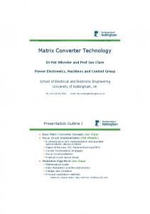
Followed by command the induction motor to specified states instead of specifying the desired states directly, we specify the rate of the desired states, x& . By swapping x& in the previous equation to x& des , we get the final form of a dynamic inversion control law:
(4)
u = g −1 ( x )[ x& des − f ( x )]
Fig. 1. Dynamic inversion process.
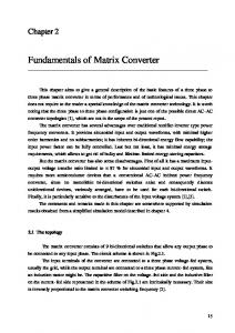
2.2 Matrix Converter Matrix Converters the direct AC-AC power converters are called Matrix Converters without using a DC-link capacitor. In a matrix converter, output voltages of desired frequency and amplitude (subjected to certain constraints) are directly synthesized from the input voltages. Matrix converters can be designed to be more compact than the conventional AC-AC converters [16]. As the matrix converter supplied from three phase voltage lines directly, to decrease the harmonics of the switches in the input current a necessary small filter is used at the input side as shown in Fig.2.
Fig. 2. Practical scheme of matrix converter.
3
MATEC Web of Conferences 225, 02022 (2018) https://doi.org/10.1051/matecconf/201822502022 UTP-UMP-VIT SES 2018
2.3 Induction Motor Model A three phase induction motor is made by stator windings and rotor windings. Can modified to two phase rotor windings and two phase stator windings. Their dynamics are described by [17]. + = (5) + = + =0 +
=0
where I, ϕ, R, u, denote current, flux linkage, resistance, and stator voltage input to induction machine respectively; the subscripts r and s denote for rotor and stator, (α, β) indicate the components of a two phase vector with respect to a fixed stator reference frame, and p represents the number of pole pairs machine and Ω the rotor speed. Assuming of linear magnetic circuits and neglecting iron losses and equal mutual inductances, the magnetic equations are [18]: = + (6) = + = + = + where Ls, Lr are auto-inductances and M is the mutual inductance; as we shall see, the assumption of linearity will be enforced by a control action which will keep the absolute value of the rotor flux below the nominal value. Eliminating Irα, Irβ and ϕsα, ϕsβ by using (6), we obtain + + − = (7)
+ + − = − + + = 0
−
+
(7)
− = 0
3 PROPOSED METHODS The proposed nonlinear dynamic inverse could be treated as compensating nonlinear term. It is same with performing an inverse of induction motor’s model that is not linear. Observe that this dynamic inverse compensates terms Ω − and etc. This let the feedback be sensitive about the great speed and especially at the time speed is evaluated. The cancellation of undesired system is attempt but we must modified the state variable ( , ) by new desired roots = , = ) (these desired roots must be chosen carefully in algebraic control law to get the desired. There are many types of desired dynamics such as ride quality, flying quality, PI, PID and also can used the distinct poles. The inverse of the B(ω) is:
4
MATEC Web of Conferences 225, 02022 (2018) https://doi.org/10.1051/matecconf/201822502022 UTP-UMP-VIT SES 2018
− () = +
So the Nonlinear Dynamic Inverse NDI controller is: − = +
2 2
2 − ℎ − ℎ 2
(8)
(9)
Fig.3 shows the block diagram of the dynamic inverse controller to 3-phase induction motor.
Fig. 3. The dynamic invers controller for induction motor.
4 Results and Discussion NDI Controller (NDI) with matrix converter topology was simulated by Matlab Simulink Package. The proposed combined NDI with MC controller was designed and simulated for 2.2kw motor is shown in fig.3. The parameter values of the IM are given in the Table 1. Table 1. Induction motor parameters. parameter power Line current Line voltage Rotor resistance Stator resistance Mutual inductance Stator inductance Rotor inductance Rotor inertia Pole pairs Viscous friction Rated speed
symbol P IL VL Rr Rs msr Ls Lr J p f w
5
Value 2.2 kW 2.8 A 380 V 4.1 Ω 9.2 Ω 0.44 H 0.43 H 0.43 H 0.042 Kg m 2 0.0031 Nm.Rad.S 310 rad/sec
MATEC Web of Conferences 225, 02022 (2018) https://doi.org/10.1051/matecconf/201822502022 UTP-UMP-VIT SES 2018
The function of matrix converter is creating the switching functions of the bidirectional switches. These functions are gate drive signals of the power switches in real converter. Fig.4 shows the deference between the output current of matrix converter without using NDI and the output current of matric converter with NDI which can note the amplitude is decreasing to low value at stable region.
(a)
(b) Fig. 4. (a) output current of matrix converter without using NDI, (b) output current with NDI.
Fig.5 illustrate the induction motor current in (α-β) coordinate system for the system with matric converter only which is has unsystematic behavior and MC combined with NDI which has systematic behavior.
(a)
6
MATEC Web of Conferences 225, 02022 (2018) https://doi.org/10.1051/matecconf/201822502022 UTP-UMP-VIT SES 2018
(b) Fig. 5. simulation results (a) matrix converter only, (b) with NDI.
Fig.6 represents the induction motor speed response when used matrix converter control only with (18%) maximum overshooting and transient to stable reign in 0.3 Sec and the output speed response with combined MC and NDI without any overshooting and stable at the same time.
(a)
(b) Fig. 6. Induction motor speed: (a) matrix converter without using NDI, (b) with NDI.
Fig.7 shows a smoothing constant delay between the rotor speed and reference speed during tracking process at increasing regime or decreasing regime. A transient pick seems in the speed error at the deviations of the speed or the load torque which illustrations the reaction of the corrector in the speed response.
7
MATEC Web of Conferences 225, 02022 (2018) https://doi.org/10.1051/matecconf/201822502022 UTP-UMP-VIT SES 2018 400 roter speed with DIC reference speed
300
speed (Rad/Sec)
200 100 0 -100 -200 -300 -400
0
1
2
3
4 5 Time (Sec)
(a)
6
7
8
9
6
7
8
9
8 6
Speed Error (Rad/Sec)
4 2 0 -2 -4 -6 -8
0
1
2
3
4 5 Time (Sec)
(b)
Fig. 7. Combined NDI with MC applied on induction motor: (a) speed tracking, (b) speed error.
The electromagnetic torque tracking the load torque at speed is constant with (0.0004%) steady state error as shown in fig.8. 60 Electromagnetic torque Load torque
50
Torque (N.M )
40
30
20
10
0
-10
0
1
2
3
4 5 Time (Sec)
6
7
8
9
Fig. 8. Torque tracking on induction motor for combined NDI with MC controller.
So when the electromagnetic torque is changed from 20 (Nm) to 50 (Nm) to tracking the reference torque the stator current will change from 8 to 15 (A) as maximum amplitude of the response as illustrated in fig.9.
8
MATEC Web of Conferences 225, 02022 (2018) https://doi.org/10.1051/matecconf/201822502022 UTP-UMP-VIT SES 2018 60 55 50
Torque (N.M)
45 40 35 30 25 20 15 10 0.35
0.4
0.45
0.5
0.55 0.6 Time (Sec)
(a)
0.65
0.7
0.75
0.8
30
Stator current (A)
20
10
0
-10
-20
-30 0.4
0.45
0.5
0.55
(b)
0.6 Time (Sec)
0.65
0.7
0.75
0.8
Fig. 9. Combined NDI with MC applied on induction motor: (a) Electromagnetic torque, (b) Stator current.
From fig.10 we can be showing a rotor flux tracking the both reference flux and flux estimation in good behavior response which are go to zero error in 0.18 (Sec). 1.8 1.6
Rotor Flux
1.4
Flux (Wb)
1.2 1 0.8 0.6 0.4
Reference Flux
0.2 0
0
0.1
0.2
0.3
0.4
(a)
9
0.5 0.6 Time (Sec)
0.7
0.8
0.9
1
MATEC Web of Conferences 225, 02022 (2018) https://doi.org/10.1051/matecconf/201822502022 UTP-UMP-VIT SES 2018 1.8 1.6
Rotor flux
1.4
Flux (Wb)
1.2 1 0.8 0.6 0.4 Estimated Flux
0.2 0
0
0.1
0.2
0.3
0.4
0.5 Time (Sec)
0.1
0.2
0.3
0.4
0.5 Time (Sec)
(b)
0.6
0.7
0.8
0.9
1
1 0.8 0.6
Flux Error (Wb)
0.4 0.2 0 -0.2 -0.4 -0.6 -0.8 -1
0
(c)
0.6
0.7
0.8
0.9
1
Fig. 10. Rotor flux tracking (a) with reference flux, (b) with estimated flux and (c) Error in tracking.
The prototype of NDI combined with MC used TMS320F28335 DSP chip as a controller, 18 IGBTs, MC board are using to validate the results. From fig.11 we show the line current in simulation and experimental results with small distortion at rotating speed 310 rad/sec.
(a)
(b) Fig. 11. Output line current: (a) simulation, (b) experimental.
10
MATEC Web of Conferences 225, 02022 (2018) https://doi.org/10.1051/matecconf/201822502022 UTP-UMP-VIT SES 2018
The experimental tracking electromagnetic torque with small ripple torque and effect on the stator current response was explained in fig.12 with small error distortion.
Stator current (A)
(a)
Time
(b)
Fig. 12. Experimental result: (a) electromagnet torque, (b) stator current tracking.
Fig.13 shows the experimental result of the rotor speed tracking of the reference speed we show there are small ripple deviation (±3 rad/sec) from the reference speed due to small ripple torque.
Fig. 13. Experimental rotor speed tracking.
5 Conclusion The different results obtained show that the developed DNI combined with MC control gives very good performances for the induction motor control. So, the estimated flux or rotor flux, after a short transient period in start-up tracking the reference flux only and is independent of the torque and speed variations. The advantages of the proposed NDI may be summarizing as follows: • Remove or decreasing the nonlinearity behaviour of the induction motor response.
11
MATEC Web of Conferences 225, 02022 (2018) https://doi.org/10.1051/matecconf/201822502022 UTP-UMP-VIT SES 2018
• • • •
Rotor flux components estimation has a high convergence rate. Decoupling the inputs by nonlinear dynamic inverse controller. The proposed NDI has a high robustness and less sensitive to parameter variations. This strategy of control gives a stable system with a satisfactory performance either with or without load variations.
References 1. 2. 3. 4. 5. 6.
7. 8.
9. 10.
11.
12. 13. 14. 15.
16.
17. 18.
Settar S. Keream, A.N.A., Ruzlaini Ghoni, Mohd Razali Daud, Youssif Al Mashhadany, Int. J. Sci. Research (IJSR), 3(5): p. 113-117 (2014) Abbas, H.A., M. Belkheiri, and B. Zegnini, Int. J. Control, 89(1): p. 140-155 (2015) CHENAFA, M., et al., Acta Electrotechnica et Informatica, 7(2): p. 1-8 (2007) Ortega, C., et al., IEEE T. Ind. Electron., 57(6): p. 2101-2110 (2010) Humada, A., et al., Int. J. Renew. Energ. Resour., 4: p. 49-53 (2014) Faraji, V., et al. Direct torque control with improved switching for induction motor drive system fed by indirect matrix converter. in National Conference on Electrical, Electronics and Computer Engineering (ELECO), (IEEE, 2010) Ruzlaini Ghoni, A.N.A., Australian J. Basic Appl. Sci., 8(4): p. 409-417 (2014) Gandomkar, A. and A. Mahmoudi. Matrix converter degrees of freedom determination for Direct Torque Control of induction machines. in Vehicle Power and Propulsion Conference (VPPC), (IEEE, 2011) Keream, S.S., et al., Mod. Appl. Sci., 9(8): p. 112 (2015) Montazeri, F. and D.A. Khaburi. Torque ripple reduction in direct torque control of induction machines by use of all voltage vectors of matrix converters. in Power Electronic & Drive Systems & Technologies Conference (PEDSTC), (IEEE, 2010) Shahmohammadi, I., M. Feyzi, and E. Babaei. Simultaneous implementation of minimum torque pulsation and unity power factor in matrix converter drive. in 18th Iranian Conference on Electrical Engineering (ICEE), (IEEE, 2010) Ali Mahmood, H., H. Mojgan, and M. Mortaza, Adv. Mat. Res., 983: p. 307-311 (2014) Zhang, B.-Y. and B. Morton, Nonlinear Anal-Theor., 32(4): p. 501-532 (1998) Ito, D., Robust dynamic inversion controller design and analysis (using the X-38 vehicle as a case study). (American Institute of Aeronautics and Astronautics, 2001) BACON, B. and A. OSTROFF, Force and Moment Approach for Achievable Dynamics using Nonlinear Dynamics Inversion. (American Institute of Aeronautics and Astronautics, 2004) Wheeler, P., J. Clare, and L. Empringham. A vector controlled MCT matrix converter induction motor drive with minimized commutation times and enhanced waveform quality. in 37th IAS Annual Meeting. Conference Record of the Industry Applications Conference, (IEEE, 2002) Marino, R., S. Peresada, and P. Valigi, IEEE T. Automat. Contr., 38(2): p. 208-221 (1993) Krause, P.C., Analysis of Electric Machinery (McGraw-Hill Book Company. New York, 1986)
12