Krishna Sekar, Member, IEEE, Kanishka Lahiri, Member, IEEE, Anand Raghunathan, Senior Member, IEEE,. Sujit Dey, Senior Member, IEEE. Abstractâ The ...
Dynamically Configurable Bus Topologies for High-Performance On-Chip Communication Krishna Sekar, Member, IEEE, Kanishka Lahiri, Member, IEEE, Anand Raghunathan, Senior Member, IEEE, Sujit Dey, Senior Member, IEEE
Abstract— The on-chip communication architecture is a major determinant of overall performance in complex System-on-Chip (SoC) designs. Since the communication requirements of SoC components can vary significantly over time, communication architectures that dynamically detect and adapt to such variations can substantially improve system performance. In this paper, we propose F LEXBUS, a new architecture that can efficiently adapt the logical connectivity of the communication architecture and the components connected to it. F LEXBUS achieves this by dynamically controlling both the communication architecture topology, as well as the mapping of SoC components to the communication architecture. This is achieved through new dynamic bridge bypass, and component re-mapping techniques. In this paper, we introduce these techniques, describe how they can be realized within modern on-chip buses, and discuss policies for run-time re-configuration of F LEXBUS based architectures. The techniques underlying F LEXBUS are general, and are applicable to a variety of bus standards. We have implemented F LEXBUS as an extension of the popular AMBA AHB bus, and have evaluated it using a commercial design flow. We report on experiments conducted to analyze its area, timing, and performance under a wide variety of system-level traffic profiles. We have applied F LEXBUS to two example SoC designs: (i) an IEEE 802.11 MAC processor, and (ii) a UMTS turbo decoder. Our results show that F LEXBUS provides gains of up to 34.55% in application data-rates over conventional architectures, with negligible area overhead and a 3.2% delay penalty. Index Terms— Communication Architectures, On-chip Buses, High-performance Communication
I. I NTRODUCTION
T
HE integration of numerous components onto a single chip is leading to rapid growth in the volume and diversity of on-chip communication traffic. Unfortunately, under current scaling trends, the performance limitations of on-chip global wiring are becoming increasingly significant [1]. As a result, the on-chip communication architecture is a critical determinant of overall performance in complex System-onChip (SoC) designs. For realizing high-performance SoCs, it is crucial for the communication architecture to be highly customized towards application traffic profiles. We view the on-chip communication architecture to be customizable towards application-specific characteristics in terms of three dimensions: 1) The design (or selection) of an appropriate communication topology. This refers to the physical structure of the communication architecture, which in general, This work was supported by the UC Discovery Grant (grant# com0210123), the Center for Wireless Communications (UC San Diego), and NEC Laboratories America.
comprises a network of bus segments interconnected by bridges. 2) The definition of a mapping of components to specific bus segments in the communication architecture. 3) The design (or selection) of communication protocols, which specify conventions that must be followed by transactions that span one or more bus segments. Most state-of-the-art communication architectures and their corresponding design flows provide customization opportunities through a static (design-time) configuration of the communication topology, mapping, and protocols. As such, they lack the ability to provide high performance in cases where the traffic characteristics vary dynamically. As shown in this paper, these variations may be significant, depending on the specific application task being processed at a given time, the subset of SoC components that are involved in executing the task, and data values encountered at run time. Furthermore, entirely different applications may execute on an SoC at different times, leading to a wide variation in traffic characteristics. Recently, adaptive on-chip communication protocols have received some interest, but they only address one of the three dimensions of communication architecture design. In this work, we focus on the challenging problem of provisioning for and exploiting flexibility in the remaining dimensions. In this paper, we present F LEXBUS, an architecture capable of dynamically controlling both the communication topology, and the mapping of components to the communication architecture. The specific contributions of our work are as follows: �
We present a detailed case study that illustrates the shortcomings of conventional communication architectures (in which the topology and component mapping is fixed) for applications whose traffic characteristics vary significantly at run time. � We present two novel hardware mechanisms underlying F LEXBUS that lend flexibility to conventional communication architectures. Bridge by-pass techniques are proposed to dynamically adapt the number of bus segments traversed by communication transactions, while component re-mapping techniques are proposed to control the mapping of components to bus segments. By controlling the topology and mapping in this manner, F LEXBUS facilitates adapting the logical connectivity of different SoC components, based on application traffic characteristics. � We describe run-time policies for selecting and applying optimized configurations in F LEXBUS-based systems under time-varying application traffic characteristics.
�
We show that F LEXBUS can be efficiently implemented within contemporary on-chip bus standards (AMBA AHB [2]), and evaluate it using commercial design tools. We present results that quantify its area, timing, and performance (under a variety of system-level traffic profiles) as compared to conventional architectures. We also evaluate its application to two example SoC designs: an IEEE 802.11 MAC processor and a UMTS Turbo Decoder. We found that F LEXBUS provides up to 31.5% and 34.55% performance gains for the MAC processor and Turbo Decoder respectively, compared to conventional architectures.
The rest of this paper is organized as follows. In Section II, we describe related work. In Section III, we define terminology commonly used in the context of bus-based communication architectures. In Section IV, we present motivational examples. Section V presents details of the F LEXBUS architecture, and Section VI discusses run-time configuration techniques. Section VII describes how F LEXBUS can be applied to complex system architectures. Section VIII reports on experimental evaluations, and Section IX concludes the paper. II. R ELATED WORK The increasing importance of on-chip communication has resulted in numerous advances in communication architecture topology and protocol design, in both industry and academia. Numerous competing commercial communication architectures are in use today (e.g., [3], [2], [4]). Recently, architectures based on more complex topologies have been proposed (e.g., [5], [6], [7], [8]). However, migration to more complex communication architectures is associated with its own set of challenges. As the number of components in a system increases, the complexity of the communication architecture can become significant, leading to large area and power overheads. This is one reason why standard buses are still the predominant architecture of choice in many systems. Moreover, many of these architectures are based on fixed topologies, and therefore, not optimized for traffic with timevarying characteristics. Advances in on-chip communication protocols have been proposed for improved sharing of on-chip communication bandwidth [9], [10], [11]. Techniques for customizing these protocols, both statically and dynamically, to adapt to traffic characteristics, have also been studied [12], [13]. Protocol customization and topology customization are complementary, and hence, may be combined to yield large performance gains. A number of automatic approaches have been proposed to statically optimize the communication architecture topology [14], [15], [16]. While many of these techniques aim at exploiting application characteristics, they do not adequately address dynamic variations in communication traffic characteristics. In order to exploit such dynamic variations, adaptive routing protocols has been proposed in the context of networkon-chip based designs [17]. Our techniques are aimed at busbased communication architectures, and focus on topology adaptation.
Transaction-level modeling and automated model refinement help raise the level of abstraction at which communication architectures are designed [18], [19]. Latency insensitive design techniques help guarantee correct system execution under variable communication delay, and hence, reduce verification effort for systems based on complex communication architectures [20]. Recent initiatives to standardize the interfaces of system components [21], [22] facilitate the customization of the communication architecture without requiring changes to the system components themselves. III. BACKGROUND Communication architecture topologies can range from a single shared bus, to which all the system components are connected, to a network of bus segments interconnected by bridges. Component mapping refers to the association between system components and bus segments. Components mapped to the communication architecture can be either masters (e.g., CPUs, DSPs), which can initiate communication transactions (reads/writes), or slaves (e.g., memories, peripherals), which can only respond to transactions initiated by a master. The internal logic of a bus segment typically comprises (i) one or more multiplexers for the proper routing of read and write data between masters and slaves, (ii) an address decoder for selecting the slave that corresponds to a read/write transaction, and (iii) a bus arbiter for determining which master should be granted access to the bus and for how many cycles. Communication protocols specify conventions for the data transfer, such as arbitration policies, burst transfer modes, etc. Bridges are specialized components that facilitate transactions between masters and slaves located on different bus segments as follows. The transaction request from the master, once granted by its local bus, is registered by the bridge’s slave interface. The bridge then forwards the transaction to it’s own master interface, which then requests access to the remote bus. On being granted, the bridge executes the transaction with the destination slave and then returns the response to it’s slave interface, which finally returns the response to the original master. IV. M OTIVATION In this section, we analyze the shortcomings of conventional communication architectures in which the topology is configured statically, using an IEEE 802.11 MAC processor design as an example. We next describe the advantages of the F LEXBUS architecture, illustrating the importance of considering the configurability of the communication architecture topology at both the system and component levels. A. Case Study: IEEE 802.11 MAC Processor The functional specification of the IEEE 802.11 MAC processor system consists of a set of communicating tasks, shown in Figure 1(a) (details are available in [23]). For outgoing frames, the LLC task receives frames from the Logical Link Control Layer, and stores them in the system memory. The Wired Equivalent Privacy (WEP) task encrypts frame data. The Integrity Checksum Vector (ICV) task works in conjunction
From Logical Link Ctrl LLC
FCS (fr. i)
FCS (fr. i-1)
WEP_ ENCRYPT
WEP_ INIT
To PHY HDR
FCS
PLI
WEP (fr. i)
WEP (fr. i+1) time
ICV TKIP
MAC_ CTRL To carrier sense
ICV
(a)
Frame Data Control Signals
(a) FCS (fr. i-1) WEP (fr. i)
FCS (fr. i) Frame Transfer (fr. i)
WEP (fr. i+1)
Frame Transfer (fr. i+1)
time
(b)
WEP
FCS
ARM946ES
AHB Arbiter
AHB I/F
AHB I/F
AHB I/F
AHB I/F
FCS (fr. i-1)
AHB
LLC
AHB I/F
(c)
Frame Buf
Key Buffer
PLI
To PHY
AHB_1 Arbiter
ARM946ES
FCS
AHB_2 Arbiter
AHB I/F
AHB I/F
AHB I/F
AHB I/F
AHB_1
LLC
AHB I/F
Bridge
AHB I/F
WEP
AHB I/F
AHB I/F
(b)
AHB I/F
FCS (fr. i+1)
FCS (fr. i)
WEP (fr. i)
Fr. Trans. (fr. i)
WEP (fr. i+1)
Multiple bus
Single bus
Multiple bus
Fr. Trans. WEP (fr. i+2) (fr. i+1) Single bus
time
Multiple bus
(c)
Fig. 2. Execution of the IEEE 802.11 MAC processor under (a) single shared bus, (b) multiple-bus, (c) Flexbus
AHB_2
AHB I/F
AHB I/F
AHB I/F
AHB I/F
Frame Buf_1
Key Buffer
Frame Buf_2
PLI
Fig. 1. IEEE 802.11 MAC processor: (a) functional specification, (b) mapping to a single shared bus architecture, (c) mapping to a multiple bus architecture
with the WEP task in order to compute a checksum over the payload. The HDR task generates the MAC header. The Frame Check Sequence (FCS) task computes a CRC-32 checksum over the encrypted frame and header. MAC CTRL implements the CSMA/CA algorithm, determines transmit times for frames, and signals the Physical Layer Interface (PLI) task to transmit the encrypted frames. The Temporal Key Integrity Protocol (TKIP), if enabled, generates a sequence of encryption keys dynamically. If TKIP is disabled, the key is statically configured by the network administrator. Figure 1(b) shows the set of components to which the above tasks are mapped in our design. An embedded processor (the ARM946E-S [24]) implements the MAC CTRL, HDR, and TKIP tasks, while dedicated hardware units implement the LLC, WEP, FCS, and PLI tasks. Other components include frame buffers for storing MAC frames, a key buffer for secure key storage, and the communication architecture. In the following sub-sections, we consider in turn, the use of two conventional communication architectures, and the proposed F LEXBUS architecture, for this design. In order to simplify the discussion, we focus on only the tasks that result in the majority of the communication traffic: WEP, FCS, and TKIP. The system was implemented using an instruction set model for the processor and RTL Verilog for the remaining hardware, and simulated using ModelSim [25] (details of this framework are described in Section VIII-A). B. Static versus Dynamic Topologies for the IEEE 802.11 MAC Processor Example 1: The first architecture we consider is illustrated in Figure 1(b), where a single AMBA AHB bus segment [2] integrates all the system components. The MAC frames are stored in a shared memory (Frame buf), and are processed
in a pipelined manner: the WEP component encrypts a MAC frame, and then signals the FCS component to start computing a checksum on the encrypted frame, while it starts encrypting the next frame. We first consider that the keys are statically configured (the TKIP task is disabled). In such a scenario, the on-chip communication traffic is largely due to the WEP and FCS components. Figure 2(a) presents a symbolic representation of an illustrative portion of the system execution traces. The figure reveals that under this architecture, at various times during system execution, simultaneous attempts by the WEP and FCS hardware to access the system bus lead to a large number of bus conflicts, resulting in significant performance loss. Experiments indicate that the maximum data rate that this architecture can support is 188 Mbps. When the TKIP task is enabled (for dynamic keys), additional traffic between the processor and the key buffer further degrades the data rate to 158 Mbps. Clearly, the single shared bus topology fails to provide high performance when there are simultaneous access attempts from different masters. In particular, it fails to exploit parallelism in the communication transactions, a drawback that can be addressed by using an architecture that uses multiple bus segments. Example 2: Figure 1(c) presents a version of the MAC processor implemented using a topology consisting of two AHB bus segments connected by a bridge. The WEP component reads frame data from memory Frame buf1, encrypts it, and then transfers the encrypted frame into Frame buf2. The FCS component processes the frame from Frame buf2, while WEP starts processing the next frame from Frame buf1. Figure 2(b) illustrates the execution trace under this architecture when the keys are statically configured. We observe that the parallelism offered by the multiple bus architecture enables the FCS and WEP tasks to process frame data stored in their local frame buffers concurrently. However, we also observe additional latencies in certain intervals (indicated by shading) where a majority of transactions need to go across the bridge, owing to the complex nature of cross-bridge transactions (described in Section III). Experiments indicate that the data rate achieved by this architecture is 201 Mbps, only a 7% improvement over the single shared bus. When the TKIP
task is enabled, the achieved data rate is 176 Mbps, a 11% improvement over the shared bus. This example illustrates that the advantage of a particular communication architecture topology depends on the characteristics of the communication traffic: when the proportion of cross-bridge traffic is low, the multiple bus architecture performs well, whereas at other times, the single shared bus architecture is superior. These examples also illustrate how during the course of execution of an application, the characteristics of the communication traffic can change significantly over time, based on the set of concurrently executing tasks, and their inter-component communication requirements. Further, communication architectures based on fixed topologies are not capable of detecting and adapting to such changes, and hence, often yield sub-optimal performance. We next consider the execution of the IEEE 802.11 MAC processor under two variants of the F LEXBUS architecture. Example 3: We first consider the case where the encryption keys are statically configured (the TKIP task is disabled). The execution trace under F LEXBUS is illustrated in Figure 2(c). The trace illustrates that the bus architecture operates in a multiple bus mode during intervals that exhibit localized communications, and hence enables concurrent processing of the WEP and FCS tasks. In intervals that require low latency communication between components located on different bus segments, a dynamic bridge by-pass mechanism is used. Under this technique, the two bus segments of the multiple bus topology are temporarily merged together into a single shared bus. The measured data rate under this architecture was found to be 248 Mbps, a 23% improvement over the best conventional architecture. The above example illustrates that by adapting the bus topology to traffic characteristics, the benefits of shared and multiple bus architectures can be combined. Note that, the bridge by-pass mechanism provides a technique to make coarse-grained (system-level) changes to the communication architecture topology. However, at times, the ability to make more fine-grained (component-level) changes to the topology is also important, as illustrated next. Example 4: We consider the case in which the TKIP task is enabled. For the F LEXBUS architecture of Example 3, the resulting increase in bus traffic on AHB 2 (Figure 1(c)) causes the achieved data rate to decrease to 208 Mbps, although it still out-performs the best conventional architecture by 18%. We next consider the execution of another version of the F LEXBUS architecture featuring a dynamic component re-mapping capability. Using this technique, while the overall architecture remains in the multiple bus configuration, the mapping of the slave Frame buf2 is dynamically switched between the two buses at specific times. In particular, it is mapped to AHB 2 as long as the FCS and WEP components are processing frame data, and to AHB 1 at times when the most recently encrypted frame needs to be efficiently transferred from Frame buf1 by the WEP task. By preserving the multiple bus topology, and thereby enabling concurrent operation of the frame transfer and the TKIP tasks, this architecture achieves a data rate of 224 Mbps, a 27% improvement over the best conventional architecture.
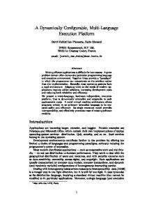
This example illustrates that in some cases, exploiting local variations in traffic characteristics through component-level changes can provide additional performance benefits. In summary, these illustrations establish that by recognizing dynamic variations in the spatial distribution of communication transactions, and correspondingly adapting the communication architecture topology (both at the system and component levels), large performance gains can be achieved. In the next three sections, we describe how these opportunities are exploited by the F LEXBUS architecture. V. F LEXBUS A RCHITECTURE In this section, we first provide a brief overview of the F LEXBUS architecture and its design goals. Next, we present a detailed description of the key techniques that underlie the F LEXBUS architecture in the context of a two-segment AMBA AHB based bus architecture. The extension of F LEXBUS to more complex communication architectures is discussed in Section VII. A. Overview The F LEXBUS architecture features a dynamically configurable communication architecture topology. The techniques underlying F LEXBUS are independent of specific communication protocols, and hence can be applied to a variety of on-chip communication architectures. In our work, we demonstrate its application to the AMBA AHB [2], a popular commercial onchip bus. F LEXBUS provides applications with opportunities for dynamic topology customization at the system level, using techniques that enable run-time fusing and splitting of bus segments. This is achieved using dynamic bridge by-pass techniques, details of which are described in Section V-B. F LEXBUS also provides customization opportunities at the component level in order to exploit local variations in traffic characteristics, by using techniques that allow components to be dynamically switched from one bus segment to another. This is achieved using component re-mapping, details of which are described in Section V-C. Numerous technical challenges need to be met in order to provide such configurability. The particular goals that were kept in mind during the design of F LEXBUS include the following: � maintaining compatibility with existing on-chip bus standards for efficient deployment � minimizing timing impact to enable high speed operation � minimizing logic and wiring complexity (hardware overhead) � providing low reconfiguration penalty to maximize the gains achieved through flexibility The rest of this section provides details on how F LEXBUS provisions for dynamic configurability keeping the above goals in mind. B. Coarse-grained Topology Control: Bridge By-pass Mechanism Figure 3 illustrates the hardware required to support dynamic bridge by-pass for an example system consisting of two
reconfigure OK
Reconfiguration Unit
reconfigure OK
config_select select_S1
busreq_AHB2
grant_M2 busreq_M2 lock_M2 grant_M1 busreq_M1 lock_M1
lock_AHB2
M1 M2
grant_AHB2
Arbiter1 Address Decoder1
busreq_BRG lock_BRG grant_BRG
address, control, wdata
busreq_M3 lock_M3 grant_M3
Address Decoder2
address, control, wdata
ready, response, rdata
ready, response, rdata
select_S2
S2 M3
Slv I/F Mst I/F
S1 AHB1
Fig. 3.
select BRG
Arbiter2 (Virtual Master)
Bridge ready
AHB2
Dynamic bridge by-pass capability in F LEXBUS
AMBA AHB bus segments, connected by a bridge. AHB1, the primary bus, has two masters (M1 and M2) and one slave (S1), while AHB2, the secondary bus, has one master (M3) and one slave (S2). Each bus segment contains an Arbiter, an Address Decoder, and multiplexers for routing the granted master’s address values, control signals and write data to the slaves, and for routing the selected slave’s ready signal, response signals and read data back to the masters. The bridge enables transactions between masters on AHB1 and slaves on AHB2. 1) Hardware Enhancements: The system can be operated in (i) a multiple bus mode or (ii) a single shared bus mode, by disabling or enabling bridge by-pass, respectively, via the config select signal, which is an output of the ”Reconfiguration Unit” module. In the multiple bus mode (config select = 0), the signals shown by the dotted arrows are inactive. The two bus segments operate concurrently, with each arbiter resolving conflicts among the masters in its own bus segment. Transactions between masters on AHB1 and slaves on AHB2 go through the bridge using the conventions described in Section III. In the single shared bus mode (config select = 1), the signals shown by the dotted arrow are active, and the bridge is “by-passed”, thereby fusing the two bus segments together. We next describe the enhancements required to the basic hardware architecture of the two segment AMBA AHB bus to support these two operating modes. Bridge: To by-pass the bridge in the single shared bus mode, the inputs to the bridge master and slave interfaces are directly routed to the outputs, by-passing the internal bridge logic (using multiplexers). This allows transaction requests from masters on AHB1 to slaves on AHB2 (and the corresponding slave responses) to reach within one clock cycle. Note that, while we illustrate bridge by-pass for a one-way bridge, the technique can be applied to two-way bridges as well. Arbiters: In the single bus mode, only one master can be granted access to the F LEXBUS fabric at any given time, whereas in the multiple bus mode, more than one master may have transactions executing in parallel. Clearly, the arbitration policies of the multiple bus mode need to be adapted for the single bus mode. A naive solution would be to designate one of the arbiters as a centralized arbiter for the single bus mode. However, this would require the centralized arbiter to be connected to the busreq, lock and grant signals of all the system
masters, resulting in large wiring overhead, and potentially large arbitration latencies. Instead, we opt for a distributed arbitration mechanism, in which one of the arbiters (Arbiter2 in Figure 3) behaves as a virtual master that is regulated by the other arbiter (Arbiter1). On receiving one or more bus requests from masters on AHB2, Arbiter2 immediately sends a bus request to Arbiter1 using the busreq AHB2 and lock AHB2 signals, which are generated by a bitwise OR of the bus request and lock signals of all the masters on AHB2. Arbiter1 arbitrates among the received bus requests from AHB1 masters as well as the virtual master, which, in effect, represents all the masters on AHB2. In parallel, in order to reduce arbitration latency, Arbiter2 arbitrates among its received bus requests. However, Arbiter2 grants the bus to the selected master only when it receives a grant (via the grant AHB2 signal) from Arbiter1. The grants for masters on AHB2 are generated by a pairwise AND of the grant AHB2 signal with the grant signals of Arbiter2. This guarantees that only one master is granted access to F LEXBUS when in the single bus mode. Note that, in the above distributed arbitration scheme, since Arbiter1 receives a single bus request (busreq AHB2) on behalf of all the masters on AHB2, the granularity at which arbitration is performed could suffer. However, in practice, this is acceptable, since bus hierarchies impose similar restrictions (i.e., bridges behave as “agents” for any of the masters on AHB1 requesting access to a remote slave on AHB2). Also, in the AMBA AHB bus protocol, the ready bus signal indicates the state of the bus to all components. In order to ensure correct operation of the system in the single bus mode, all components should observe the same ready signal. This is done by routing the ready signal of AHB1 to AHB2. Note that, the combinational loop between the multiplexers (Figure 3) is a false loop, i.e., it is never enabled during operation. Address Decoders: The address decoders on the two bus segments require no change, since the address maps of the slaves and their mapping to the bus segments does not change under dynamic bridge by-pass. Reconfiguration Unit: The Reconfiguration Unit (Figure 3) is a new hardware component that is introduced to enable dynamic topology configuration. It is responsible for selecting the bus configuration at run-time, and for ensuring correctness of system operation while switching between the two configurations. It can either be directed by any master to change the bus configuration, or it can make configuration decisions automatically (using policies such as described in Section VI). On the selection of a new configuration, it first asserts the reconfigure signal to the arbiters. On receiving this signal, the arbiters terminate the current transaction (unless the master has acquired a lock on the bus), deassert all grant signals, and assert the OK signal. On receiving the OK signal from both the arbiters, the Reconfiguration Unit toggles the config select signal. The exact overhead of reconfiguration depends on the precise set of pending bus transactions. In our design, the worst case overhead of bus reconfiguration for the two AHB segment AMBA based system was observed to be 17 cycles (assuming the bus is not locked and all slaves have single cycle response). This overhead should be taken into account while making bus configuration decisions (described in Section VI).
M2 Reconfiguration config_select_M2 Unit
grant_M1 busreq_M1 lock_M1
SWITCH_M lock_M2
lock_M2
busreq_M2 grant_M2
busreq_M2 grant_M2
Arbiter1 address, control, wdata
M1
busreq_BRG lock_BRG grant_BRG
busreq_BRG lock_BRG grant_BRG
Mst I/F
Mst I/F
Slv I/F
Slv I/F
ready, response, rdata
S1 Address Decoder1
select_S1
AHB1
select BRG
grant_M3 busreq_M3 lock_M3
Arbiter2 address, control, wdata
M3
ready, response, rdata
BRG
select_S2
S3 select BRG select_S2
Address Decoder2
select_S3
AHB2
config_select_S2 SWITCH_S
S2
Fig. 4.
Dynamic component re-mapping capability in F LEXBUS
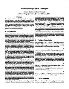
2) Delay Impact: The addition of logic and wiring for dynamic bridge by-pass results in a slight increase in the critical path delay of the bus. The true critical path in the multiple bus mode is shorter than that in the single bus mode, since many long paths of the single bus mode are false paths in the multiple bus mode (shown by the dotted arrows in Figure 3). However, as borne out by experiments presented in Section VIII, the delay penalty of each mode compared to the corresponding static architectures is small, and is more than compensated for by the performance improvements achieved by exploiting the flexibility of the architecture. When the worst case delays of the single bus mode and the multiple bus mode are comparable, it is feasible to always operate F LEXBUS at a single frequency determined by the larger of the two delays. However, in some cases, the delay in the single bus mode maybe much larger than that in the multiple bus mode. Also, some multiple bus systems operate different bus segments at different frequencies in order to support high performance components such as CPUs on one bus, and low performance peripherals on a secondary bus. In such scenarios, the F LEXBUS frequency needs to be adapted, based on its current configuration. Using a programmable PLL to achieve this would lead to a high reconfiguration penalty (hundreds of �secs). However, we observe that since we only need to switch between two clock frequencies, two PLLs in conjunction with a dynamic clock source switching circuit [26] could be used in such a scenario for efficient frequency adaptation. C. Fine-grained Topology Control: Component Re-mapping Mechanism Figure 4 shows a two segment AMBA AHB bus architecture, which implements a dynamic re-mapping capability for master M2 and slave S2. Dynamic re-mapping allows the mapping of each of these components to be dynamically switched between AHB1 and AHB2. 1) Hardware Enhancements: The mapping of M2 and S2 is selected by the signals, config select M2 and config select S2, respectively, which are generated by the Reconfiguration Unit.
The hardware enhancements that are required to the AMBA AHB bus architecture to enable this are described next. Switches: The signals of a re-mappable master or slave are physically routed to both AHB1 and AHB2. However, the switch boxes, SWITCH M and SWITCH S, activate the signals to and from only one of the bus segments using multiplexers, depending on the configuration. Note that, only a subset of the master and slave signals require to be switched in the AMBA AHB protocol. Bridge: The bridge does not require any changes to enable component re-mapping, since the multiple bus structure of the communication architecture is preserved. However, note that, component re-mapping can lead to error responses in the case of one-way bridges. For example, assuming that BRG in Figure 4 is one-way (with AHB1 being the primary bus and AHB2 the secondary bus), and that M2 is mapped to AHB2, then if M2 generates a request for S1, it would receive an error response. Therefore, in the presence of masters that cannot handle error responses, it can be safely applied only in the case of two-way bridges. Arbiters: The arbiters on the two bus segments need to be designed to arbitrate amongst all the masters that can potentially be mapped to their respective bus segment. No other changes are required, since master bus requests are only sent to the arbiter on the bus to which they are currently mapped. Address Decoders: To enable dynamic slave re-mapping, reprogrammable address decoders are required. Depending on the mapping of the slaves, the address decoders on the two bus segments are reconfigured to generate the correct slave select signal. For example, when S2 is mapped to AHB1, on observing an address belonging to S2 on the address bus, Decoder1 asserts the select S2 signal, while Decoder2 asserts the select BRG signal. The situation is reversed when S2 is mapped to AHB2. This is done by switching the mapping of the address space of S2 between BRG and S2 in the decoder, depending on the config select S2 signal. Reconfiguration Unit: The Reconfiguration Unit is a new hardware component that is responsible for managing dynamic component re-mapping. It can either be directed by a bus master to change the mapping of the re-mappable masters and slaves, or it can make configuration decisions automatically (using policies such as described in Section VI). On the selection of a new configuration, it is responsible for generating the appropriate configuration select signals. In order to ensure correct operation of the system during re-mapping, the Reconfiguration Unit monitors the master’s busreq M2 and slave’s select S2 signals to determine if they are currently active on the bus, and if not, the corresponding config select signal is toggled. The rest of the bus continues operating without interruption. 2) Delay Impact: The extra logic and wiring required to enable component re-mapping may lead to a slight increase in the critical path delay of the bus. The more the number of components made re-mappable, the greater is this incurred overhead. However, we expect that in practice, only a few judiciously selected components with large communication requirements would need to be made re-mappable. As shown
by experiments in Section VIII, this overhead should be more than compensated for by the performance improvements achieved through adaptation. If the two bus segments operate at different clock frequencies, then dynamic component remapping can only be applied to masters and slaves which are capable of operating at both clock frequencies. In this case, re-mapping also involves changing the clock source of the remapped component using techniques such as described in [26]. VI. DYNAMIC C ONFIGURATION P OLICIES F OR F LEXBUS In this section, we describe run-time policies for adapting the F LEXBUS configuration based on changes in the characteristics of the on-chip communication traffic. We discuss these policies in the context of two segment buses, considering in turn, bridge by-pass and component re-mapping. Extension of these policies to more general communication architecture topologies is discussed in the next section. The problem of dynamically choosing the optimum configuration of the F LEXBUS architecture based on an observation of the characteristics of the communication traffic can be addressed using several approaches. One approach would be to design application-specific or system-specific bus reconfiguration policies based on design-time analysis of the bus traffic characteristics. However, for complex systems with many components, the design of such customized policies may not be feasible. In the past, stochastic control policies have been proposed to address a similar problem in the domain of dynamic power management, where the optimum power state of components (active, idle) needs to be selected for dynamically varying system workloads [27]. Numerous heuristic approaches that attempt to predict future behavior based on an observed history of the workload have also been proposed to address the same problem [28]. In our work, we examine history-based techniques in further detail. Let us consider a F LEXBUS system featuring dynamic bridge by-pass between two bus segments, BUS1 and BUS2. Let NBUS 1 , NBUS 2 and NBRG represent the number of local transactions on BUS1, number of local transactions on BUS2 and number of transactions between the two bus segments, respectively, during an observation interval. A transaction refers to a single bus access (e.g., a burst of 5 beats constitutes 5 transactions). The time taken to process this traffic under the single bus mode, TSingle , is given by:
TSingle = (NBUS1 + NBUS2 + NBRG) � CL � tSB (1) where CL is the average number of cycles for a local bus transaction, and tSB is the clock period in the single bus mode,
since all transactions are on the same bus. Similarly, the time taken under the multiple bus mode, TMultiple , is approximated by:
TMultiple =max(NBUS1 ; NBUS2 ) � CL � tMB + NBRG � CB � tMB (2) where CB is the average number of cycles for a cross-bridge transaction, and tMB is the clock time period in the multiple bus mode. If TSingle < TMultiple , then the single bus mode
is preferred, else the multiple bus mode is better. Each bus
segment is enhanced with extra logic to observe and record the number of bus transactions of each type at run-time over a time period TP . At the end of the time period, the reconfiguration unit reads these values and selects the new configuration based on the above criterion. The choice of an appropriate configuration time period, TP , is crucial. Smaller time periods enable the policy to be more responsive to variations in the traffic characteristics. However, if the traffic characteristics change rapidly, this might lead to excessive oscillations between the configurations, thus potentially degrading the performance due to the reconfiguration overhead. Therefore, in our policy we use an adaptive time period, TP , which is selected as follows. Let C denote the number of times the bus was reconfigured over the last � clock cycles. If C=� > �1 , then the time period, TP , is doubled, if C=� < �2 , then TP is halved, else it is unchanged. �1 and �2 represent two thresholds, and depend on the reconfiguration overhead. In our experiments with an example eight master and eight slave system (described in Section VIII-A), we observed an average reconfiguration overhead of 10 cycles, for which � = 250 cycles, �1 = 0:0025, and �2 = 0:001 proved effective. We conclude that, in general, these parameters should be carefully set, based on an analysis of the traffic characteristics of the application. Let us next consider a F LEXBUS architecture consisting of two bus segments, BUS1 and BUS2, connected by a bridge, and with some re-mappable master and slave components. The problem of dynamic component re-mapping is to select at runtime the mapping of the re-mappable components to either BUS1 or BUS2. For this, we propose a history-based policy, in which for each re-mappable master (or slave), the number of transactions to (or from) components on either bus segment is monitored over an observation time period, based on which the configuration for the next time period is selected. The optimal mapping of components to buses is one that minimizes the number of transactions across the bridge (to reduce bridge overhead), while balancing the number of transactions on the two bus segments (to have concurrent operation). This problem maps to the graph bisection problem, which is NPcomplete [29]. Therefore, we make use of the following simple strategy. For each re-mappable component, the difference between its number of cross-bridge and local transactions is monitored. The component for which this difference is positive and maximum is selected to be re-mapped. The time period over which transactions are monitored is adapted as in the bridge by-pass approach. VII. S CALABILITY O F T HE F LEXBUS A PPROACH In this section, we discuss how the architectural mechanisms underlying F LEXBUS are extendable to complex communication architectures. We consider in turn, the scalability of the hardware support for dynamic bridge by-pass and component re-mapping. A. Dynamic Multi-bridge By-pass Complex communication architectures may consist of numerous bus segments connected by multiple bridges. It may
VM
ARB1 Bus1
DEC1
VM
B R G 1
ARB2 Bus2
DEC2
VM
B R G 2
ARB3 Bus3
DEC3
B R G 3
ARB4 Bus4
DEC4
Slave
Fig. 5. Example system with four bus segments, and possible assignment of arbiters as virtual masters
be necessary, at certain times, to merge multiple (more than two) bus segments into a single shared bus, depending on the traffic characteristics. In order to achieve this, all the bridges that integrate these bus segments must be made by-passable as described in Section V-B.1. In doing so, the architecture needs to ensure that only one master gets access to the merged shared bus at any point of time. The distributed arbitration mechanism described for one bridge (Section V-B.1) can be extended to multiple bridges as follows. When the architecture is in the single bus mode, the arbiters co-ordinate by acting as virtual masters and forwarding their bus requests to adjacent arbiters. The decision of which arbiters to designate as virtual masters and to which arbiter to forward their bus requests is performed statically, and is crucial to ensure correct operation of the system. For a N segment bus, any one of the N arbiters is a candidate for being the arbiter of the bus when all the bridges are by-passed. All the other arbiters are designated virtual masters, and they must forward their requests to the selected arbiter. Figure 5 illustrates an example system consisting of four bus segments and three bridges, where as many as all three bridges can be by-passed simultaneously at run-time. In the illustration, ARB4 acts as the arbiter when Bridges 1, 2 and 3 are by-passed, while ARB1, ARB2, and ARB3 are the virtual masters (VM). Among the N alternatives, the best choice is the one that minimizes wiring overhead and delay penalty. The same conclusions hold for any arbitrary connection of the bus segments (hierarchical bus etc). B. Scalability of Component Re-mapping In complex communication architectures it may be necessary to provide support for dynamically re-mapping a component, either a master or a slave, to multiple (greater than two) bus segments. In order to provide this support, the basic approach described in Section V-C.1 is extended as follows. The signals of the re-mappable component are physically connected to all the bus segments to which it can be potentially mapped. An appropriate switch is used to ensure that only one set of signals is active at any point of time. For slave re-mapping, the address decoders on each bus segment are configured to generate the correct slave select signals by reprogramming the address maps. This needs to be done not only for the address decoders on the bus segments to which the slave can be mapped, but also for intermediate address decoders. For example, in Figure 5, suppose a slave is remappable to either Bus1 or Bus4. Now, when it is mapped to Bus1, on observing an address belonging to the slave, the address decoders DEC1, DEC2, DEC3 and DEC4 should
select the slave, BRG1, BRG2 and BRG3, respectively, while when it is mapped to Bus4, the decoders should select BRG1, BRG2, BRG3 and the slave, respectively. The two F LEXBUS mechanisms, bridge by-pass and component re-mapping, can be applied together to provide maximum performance benefits through adaptation. C. Applying F LEXBUS in Complex Communication Architectures In order to provide maximum flexibility during run-time configuration, all the bridges in the system can be made bypassable, and all the master and slave components can be made re-mappable to all bus segments using the techniques described in Sections VII-A and VII-B. However, in practice, this would lead to unacceptably high overheads, potentially negating any performance improvements through adaptation. This is because as more and more bus segments are merged together, the associated delay penalty due to extra logic and wiring overhead increases. Similarly, as a component is made re-mappable to more and more bus segments, its performance may decrease due to the overhead of the switch and additional wiring. Also, a bus segment with many re-mappable components may incur large delay penalty due to the extra wiring and logic overhead in the bus required to provision for the additional masters and slaves. Clearly, this calls for techniques that judiciously provision for such flexibility in the communication architecture by balancing the overhead with the benefit, and corresponding techniques for exploiting the flexibility offered. We envision an automatic methodology for applying F LEXBUS in complex communication architectures, wherein based on an analysis of application traffic profiles, the set of desired configurability options (namely, which bridges should be augmented with bypass support, and which components should be augmented with re-mapping support) are automatically and optimally inserted in the communication architecture. Such an automatic methodology is a subject for future research. VIII. E XPERIMENTAL R ESULTS In this section, we present experimental studies that evaluate the F LEXBUS architecture. We present hardware implementation results, followed by an analysis of the F LEXBUS architecture under systematically varied traffic profiles. We then study the performance of F LEXBUS when applied to two Systemon-Chip designs: (a) an IEEE 802.11 MAC processor, and (b) a UMTS Turbo decoder, to evaluate its performance in the context of real applications. A. Experimental Methodology For our experiments, we considered three different SoC architectures. The first is a generic SoC consisting of two bus segments connected by a bridge, each of which integrates four masters and four slaves. The masters are attached to VERA bus-functional models that can be programmed to generate bus traffic with desired properties [30]. We use this SoC to study the performance of FLEXBUS under systematically varied traffic profiles, as well as its hardware complexity. The
20
DSP2
Single Shared Bus FLEXBUS: 2 Freqs
DPSRAM2 SPSRAM3
15
Total Latency (us)
ARM4
SPSRAM4
10
UDL2 AHB2
ARM3
ARM1
UART1 BRG UART2
5
SPSRAM1
0
DPSRAM1
0
SPSRAM2 AHB1
ARM2
UDL1
Single Shared Bus Multiple Bus FLEXBUS (single bus mode) FLEXBUS (multiple bus mode)
Total Area (sq. mm) 82.12 84.27
10
20
30
40
50
60
70
% Traffic across Bridge
80
90
100
Fig. 7. Performance comparison under varying volume of cross-bridge traffic DSP1
optimal buffer insertion [35] and Metal 6 wiring. The designs were annotated with these wire delays and Synopsys Design Compiler [33] was used for critical path delay estimation.
(a) Floorplan under the F LEXBUS architecture
Bus Architecture
Multiple Bus FLEXBUS: 1 Freq
Delay (ns) 4.59 3.79
Frequency (MHz) 218 264
4.72
212
3.93
254
82.66
(b) Total chip area, bus delay and bus clock frequency under different communication architectures Fig. 6. Hardware implementation results for example eight master and eight slave system
second system is the IEEE 802.11 MAC processor (described in Section IV-A). This system was implemented using an instruction set model for the ARM processor, and RTL Verilog descriptions for the remaining hardware. The third system is the UMTS Turbo decoder (described in Section VIII-E), which was entirely implemented using RTL Verilog. Reference AMBA AHB RTL implementations of the conventional communication architectures for each system were generated using the CoreConsultant tool of the Synopsys Designware AMBA tool suite [30]. F LEXBUS was implemented by enhancing the reference AMBA AHB implementations as described in Section V. The Reconfiguration Unit incorporating the runtime policies described in Section VI was implemented in Verilog. Performance analysis results were obtained through simulations using ModelSim [25]. For chip-level area and delay comparison, we generated floorplans of all the systems [31]. For this, area estimates for the different components were obtained from datasheets [32] in some cases, and from synthesis using Synopsys Design Compiler [33] in cases where RTL descriptions were available, for the NEC 0.13�m technology [34]. The floorplanner was modified to report wirelengths of the global wires that constitute the different communication architectures. Global wire delay was calculated assuming delay
B. Hardware Implementation Results We report area and timing results for the generic SoC described in the previous subsection under (i) F LEXBUS with dynamic bridge by-pass, (ii) single shared bus, and (iii) multiple bus architectures. Figure 6(a) shows the floorplan of the system under the F LEXBUS architecture. The results of these studies are shown in Figure 6(b). From the figure, we observe that the total chip area of the system with the multiple bus architecture is 2% larger than that for F LEXBUS, since the floorplanner achieves more optimized wirelengths for the multiple bus architecture by incurring a small area penalty. The figure also presents delay results under different bus architectures. For the F LEXBUS, the critical path delay in the multiple bus mode is smaller than that in the single bus mode since many long paths of the single bus mode are false paths in the multiple bus mode. This corresponds with the observation that the static multiple bus architecture can operate at a higher frequency than the static single shared bus due to shorter wirelengths and lesser bus loading. F LEXBUS incurs a 3.2% delay penalty on average compared to the statically configured architectures, due to extra wiring and logic delay. However, this timing penalty is more than compensated for by the performance benefits of adapting the bus to changing traffic characteristics, as borne out by the following subsections. C. Performance Under Synthetic Traffic Profiles We performed experiments to analyze the performance of the F LEXBUS architecture compared to the statically configured architectures under a wide range of communication traffic. Deterministic Traffic Profiles: For this experiment, we consider simple traffic profiles that consist of two phases. In the first phase, all the traffic is local i.e., between masters and slaves on the same bus segment (no traffic across the bridge), while in the second phase, all the traffic is between masters on AHB1 and slaves on AHB2 (all traffic across the
bridge). Numerous profiles were generated by varying the relative volume of traffic in each phase. The conventional architectures were operated at the clock frequencies shown in Figure 6(b). For F LEXBUS, we considered two cases: (i) it is always operated at 212 MHz, and (ii) the clock frequency is switched between 212 MHz and 254 MHz depending on the configuration. Figure 7 shows the total latency (Y-axis) for the different traffic profiles (X-axis) under the different bus architectures. For the single bus, the latency remains constant since all the components are connected to the same bus. The multiple bus performs much better than the single bus when there is less traffic across the bridge, but its performance rapidly deteriorates with increasing cross-bridge traffic due to the large delay penalty of the bridge. Both variants of F LEXBUS achieve substantial performance gains over the conventional architectures across most of the traffic space. As expected, for purely local traffic, F LEXBUS performance is almost identical to a multiple bus architecture, while for heavy cross-bridge traffic, it is similar to the single shared bus.
Cross Bridge Traffic
Local Traffic
0
500
1000
1500
2000
2500
3000
Amount of Data Generated (Bytes)
(a) Example traffic profile
Single Bus Mode
Multiple Bus Mode
0
500
1000
1500
2000
2500
3000
Amount of Data Transferred (Bytes)
(b) Bus configurations selected by the policy
(1-P1) Local Traffic
(1-P2) Cross-bridge Traffic
P2
Fig. 8. Two state Markov model to systematically generate varying traffic profiles
Cumulative Latency (us)
35
P1
Single Shared Bus
30
TABLE I P ERFORMANCE OF THE IEEE 802.11 MAC PROCESSOR UNDER DIFFERENT COMMUNICATION ARCHITECTURES
Bus Architecture Single Shared Bus Multiple Bus FLEXBUS (Dynamic Bridge By-pass) FLEXBUS (Dynamic Component Re-mapping) Ideally Reconfigurable Bus
Computation Time (ns) Data Transfer Time (ns) Total Time (ns) 42480 26905
12800
42480 39705
27025
5290
32315
27010
5270
32280
26905
5120
32025
FLEXBUS
25 20 15 10 5 0 0
Random Traffic Profiles: In the next experiment, the effectiveness of F LEXBUS under run-time variations in traffic characteristics is evaluated. The traffic profiles were generated using a two-state Markov model, where each state corresponds to either local traffic or cross-bridge traffic, as illustrated in Figure 8. Varying the transition probabilities of the edges (P1 and P2) allowed us to vary the granularity with which the two traffic types are interleaved in the profile. Figure 9(a) shows a representative traffic profile consisting of a mix of local and cross-bridge traffic. Figure 9(b) shows the runtime configuration decisions taken by the policy described in Section VI. Figure 9(c) plots the cumulative latency of the different architectures for this traffic profile. We observe that the policy successfully adapts F LEXBUS to changes in the traffic characteristics, achieving significant performance benefits over the static single shared bus (21.3%) and multiple bus (17.5%) architectures. Also, the policy achieves performance
Multiple Bus
500
1000
1500
2000
2500
3000
Amount of Data Transferred (Bytes) (c) Cumulative latency under different bus architectures Fig. 9.
Performance of F LEXBUS with run-time configuration policy
benefits even under frequent variations in the traffic profile (between 1050 seconds and 1870 seconds), by increasing the configuration time period, TP , thus configuring the bus at larger time granularities. D. Application to an IEEE 802.11 MAC Processor Next, we examine the performance of F LEXBUS and conventional communication architectures for the IEEE 802.11 MAC processor described in Section IV-A. We considered two variants of the F LEXBUS architecture, (i) featuring dynamic bridge by-pass, and (ii) featuring dynamic component re-mapping (Frame buf2 being a re-mappable slave). For the first variant, the bus configuration policy described in Section VI selects when to disable or enable the bridge at run-time. For the second variant, since Frame buf2 is the only re-mappable component, the re-mapping policy dynamically maps it to the bus segment from which it receives the most number of transactions. All the buses were operated at 200 MHz. Table I shows the average time taken to process a single frame (of size 1 KB) under the different bus architectures. From the table, we see that the times required by both variants of the F LEXBUS architecture are significantly
X
Z1
Z2
Le1
De-interleaver
Interleaver Le2 ~ Le1 Component Decoder 2
Interleaver ~ X'
Z2'
(a)
(b) AHB Arbiter
DCDR 1
INT/DE-INT
AHB I/F
AHB I/F
AHB I/F
DCDR 2 AHB I/F
AHB AHB I/F
Frame Mem
AHB_1 Arbiter
DCDR 1
INT/DE-INT
DCDR 2
AHB I/F
AHB I/F
AHB I/F
AHB I/F AHB I/F
Finally, we apply F LEXBUS to the design of a Turbo decoder for the Universal Mobile Telecommunications System (UMTS) specification, and evaluate its performance compared to conventional static bus architectures. Turbo coding has received considerable attention in recent years due to its near Shannon capacity performance [36], and has been included in the specifications for both the WCDMA (UMTS) [37] and cdma2000 [38] third-generation cellular standards. Figure 10(a) and (b) show the functional blocks in a turbo encoder and decoder, respectively (details are available in [39], [40]). The turbo encoder consists of two recursive systematic convolutional (RSC) encoders connected in parallel with an interleaver between them. For an input frame X , the outputs of the turbo encoder are the systematic bits (X ), and the parity bits from the two RSC encoders (Z1 and Z2 ). The turbo decoder consists of two RSC component decoders linked together by an interleaver and a de-interleaver. The inputs to the turbo decoder are the noise-contaminated received frame systematic bits (X 0 ) and parity bits (Z10 and Z20 ). As indicated by the feedback path, the turbo decoder operates in an iterative manner. In each iteration, the first component decoder generates soft outputs (Le1 ) about the likely values of the bits to be decoded in terms of the log-likelihood ratios (LLR - logarithm of the ratio of the probability of the bit being 1 to the bit being 0), which are then interleaved and input to the second decoder. The second decoder then generates another set of LLR values (Le2 ), which are fed back to the first decoder after de-interleaving them. After a number of such iterations (typically 8 for low bit error rate), a hard (0 or 1) decision is taken about the value of each bit. Figure 10(c) shows the mapping of the Turbo decoder functional blocks to hardware components in our design. The two RSC decoders are based on the log-MAP algorithm [41] and are implemented by custom hardware components, DCDR1 and DCDR2, respectively, using the sliding window approach [42]. The interleaver and de-interleaver functionality is implemented by the INT/DE-INT hardware component. The system processes two input frames simultaneously. While DCDR1 processes the first frame, DCDR2 processes the second frame. On completion, they signal the INT/DE-INT, which then interleaves the output of DCDR1 and de-interleaves the output of DCDR2. The processing of the frames is now swapped with DCDR1 processing the second frame and DCDR2 processing the first frame. After eight such iterations, the decoded bits are read out and the system starts processing a new pair of frames.
O/P Component Decoder 1
Z1'
Interleaver RSC Encoder 2
X'
(c)
E. Application to a UMTS Turbo Decoder Design
~ Le2
X RSC Encoder 1
AHB_1
(d)
BRG
AHB_2 Arbiter AHB I/F
AHB_2
AHB I/F
smaller compared to the conventional architectures. The data rate increase due to F LEXBUS over the single shared bus is 31.5% and over the multiple bus is 23%. The table also shows the upper bound on performance, obtained using an ideal reconfigurable bus (zero reconfiguration overhead) with an ideal reconfiguration policy (complete knowledge of future bus traffic). We observe that for this system, F LEXBUS and its associated policies perform close (data rate within 1%) to the ideal case.
AHB I/F
AHB I/F
Frame Mem 1
Frame Mem 2
Fig. 10. UMTS Turbo encoder and decoder: (a) encoder functional blocks, (b) decoder functional blocks, (c) mapping to a single shared bus architecture, (c) mapping to a multiple bus architecture
Figure 10(c) shows the design under a single shared bus architecture with Frame mem storing all the input and intermediate frame data. Figure 10(d) shows the design implemented using a multiple bus architecture, with DCDR1, INT/DEINT and Frame mem1 mapped to AHB1, and DCDR2 and Frame mem2 mapped to AHB2. The input and output frame data of DCDR1 and DCDR2 are stored in Frame mem1 and Frame mem2, respectively. The INT/DE-INT block processes the output of DCDR1 from Frame mem1 and stores the interleaved data in Frame mem2, and de-interleaves the output of DCDR2 from Frame mem2 and stores it in Frame mem1. The system is also evaluated under the two variants of the F LEXBUS architecture, (i) featuring dynamic bridge by-pass, and (ii) featuring dynamic component remapping (Frame mem2 being a re-mappable slave), and using the bus configuration policy described in Section VI. All the buses were operated at 200 MHz. Table II shows the performance of the system while processing two frames each of size 1 KByte, in terms of the time taken for the decoding phase, and interleaving and deinterleaving phase for each half-iteration, the total time to process both the frames, and the corresponding data rate, under the different bus architectures. From the table, we see that the multiple bus performs better compared to the single shared bus during the decoding phase by avoiding bus conflicts between TABLE II P ERFORMANCE OF THE UMTS T URBO DECODER UNDER DIFFERENT COMMUNICATION ARCHITECTURES
Bus Architecture Single Shared Bus Multiple Bus FLEXBUS (Dynamic Bridge Bypass) FLEXBUS (Dynamic Component Re-mapping)
Decoding Interleaving/ Total Time Data Rate Phase (ns) De-interleaving Phase (ns) (ns) (Mbps) 20620 10910
16080 24680
587200 569440
3.4877 3.5965
11095
16225
437120
4.6852
11075
16200
436400
4.6929
DCDR1 and DCDR2, but suffers during the interleaving/deinterleaving phase due to the bridge overhead. Both versions of F LEXBUS perform much better than either static architecture, achieving a data rate improvement of 34.55% over the single shared bus and 30.49% over the multiple bus architecture. IX. C ONCLUSION In this paper, we illustrated that significant performance benefits can be achieved by configuring the on-chip communication architecture topology in response to variations in traffic characteristics. We presented F LEXBUS, a novel dynamically configurable communication architecture, featuring two different configurability options: (i) dynamic bridge by-pass, and (ii) dynamic component re-mapping, and described techniques for efficiently adapting F LEXBUS at run-time. Extensive experiments on F LEXBUS using a commercial design flow to analyze its area, timing, performance under a wide variety of traffic profiles, and its application to the design of an IEEE 802.11 MAC processor and a UMTS Turbo decoder, demonstrate its superiority over conventional communication architectures. R EFERENCES [1] R. Ho, K. W. Mai, and M. A. Horowitz, “The future of wires,” Proc. IEEE, vol. 89, no. 4, pp. 490–504, Apr. 2001. [2] “AMBA 2.0 specification,” http://www.arm.com/products/solutions/ AMBA Spec.html. [3] “CoreConnect bus architecture,” http://www-03.ibm.com/chips/ products/coreconnect/. [4] “Sonics integration architecture,” sonics Inc., http://www.sonicsinc.com. [5] S. J. Lee, S. J. Song, K. Lee, J. H. Woo, S. E. Kim, B. G. Nam, and H. J. Yoo, “An 800Mhz star-connected on-chip network for application to system on a chip,” in Proc. Int. Solid State Circuits Conf., Feb. 2003, pp. 468–469. [6] A. Adriahantenaina, H. Charlery, A. Greiner, L. Mortiez, and C. A. Zeferino, “SPIN: a scalable, packet switched, on-chip micro-network,” in Proc. Design Automation & Test Europe (DATE) Conf., 2003, pp. 70–73. [7] F. Karim and A. Nguyen and S. Dey, “An interconnect architecture for networking system on chips,” IEEE Micro, vol. 22, no. 5, pp. 36–45, Oct. 2002. [8] S. I. Han, A. Baghdadi, M. Bonaciu, S. I. Chae, and A. A. Jerraya, “An efficient scalable and flexible data transfer architecture for multiprocessor SoC with massive distributed memory,” in Proc. Design Automation Conf., June 2004, pp. 250–255. [9] D. Wingard and A. Kurosawa, “Integration architecture for system-ona-chip design,” in Proc. Custom Integrated Circuits Conf., May 1998, pp. 85–88. [10] R. Yoshimura, K. T. Boon, T. Ogawa, S. Hatanaka, T. Matsuoka, and K. Taniguchi, “DS-CDMA wired bus with simple interconnection topology for parallel processing system LSIs,” in Proc. Int. Solid-State Circuits Conf., Feb. 2000, pp. 370–371. [11] K. Lahiri, A. Raghunathan, and G. Lakshminarayana, “LOTTERYBUS: a new communication architecture for high-performance system-on-chip designs,” in Proc. Design Automation Conf., June 2001, pp. 15–20. [12] K.Lahiri, A.Raghunathan, and S.Dey, “Design of high-performance system-on-chips using communication architecture tuners,” IEEE Trans. Computer-Aided Design, vol. 23, no. 6, pp. 919–932, 2004. [13] T. Meyerowitz, C. Pinello, and A. Sangiovanni-Vincentelli, “A tool for describing and evaluating hierarchical real-time bus scheduling policies,” in Proc. Design Automation Conf., June 2003, pp. 312–317. [14] R. B. Ortega and G. Borriello, “Communication synthesis for distributed embedded systems,” in Proc. Int. Conf. Computer-Aided Design, Nov. 1998, pp. 437–444. [15] A. Pinto, L. P. Carloni, and A. Sangiovanni-Vincentelli, “Constraintdriven communication synthesis,” in Proc. Design Automation Conf., June 2002, pp. 783–788.
[16] S. Pasricha, N. Dutt, and M. Ben-Romdhane, “Fast exploration of bus-based on-chip communication architectures,” in Proc. Int. Conf. Hardware/Software Codesign and System Synthesis, Sept. 2004, pp. 242–247. [17] J. Hu and R. Marculescu, “DyAD — smart routing for networks-onchip,” in Proc. Design Automation Conf., June 2004, pp. 260–263. [18] J. A. Rowson and A. Sangiovanni-Vincentelli, “Interface-based design ,” in Proc. Design Automation Conf., June 1997, pp. 178–183. [19] M. Caldari, M. Conti, M. Coppola, S. Curaba, S. Pieralisi, and C. Turchetti, “Transaction-level models for AMBA bus architecture using SystemC 2.0,” in Proc. Design Automation & Test Europe (DATE) Conf., 2003, pp. 26–31. [20] L. P. Carloni, K. L. McMillan, and A. L. Sangiovanni-Vincentelli, “Theory of latency-insensitive design,” IEEE Trans. Computer-Aided Design, vol. 20, no. 9, pp. 1059–1076, Sept. 2001. [21] “Virtual component interface standard version 2 (OCB 2 2.0,” http: //www.vsia.org/documents/vsiadocuments.htm#ocb220. [22] “Open core protocol international partnership (OCP-IP),” http://www. ocpip.org. [23] “Wireless LAN Medium Access Control (MAC) and Physical Layer (PHY) Specifications,” aNSI/IEEE Std 802.11, 1999 Edition (R2003) http://standards.ieee.org/getieee802/download/802.11-1999.pdf. [24] “ARM9E Family: ARM946E-S,” http://www.arm.com/products/CPUs/ ARM946E-S.html. [25] “Modelsim 5.7e,” http://www.model.com. [26] R. Mahmud, “Techniques to make clock switching glitch free,” [Online]. Available: http://www.eetimes.com/story/0EG20030626S0035. [27] L. Benini, A. Bogliolo, G. A. Paleologo, and G. D. Micheli, “Policy optimization for dynamic power management,” IEEE Trans. ComputerAided Design, vol. 18, no. 6, pp. 813–833, June 1999. [28] F. Douglis, P. Krishnan, and B. Bershad, “Adaptive disk spin-down policies for mobile computers,” in USENIX Symp. Mobile and Location Independent Computing, Apr. 1995, pp. 121–137. [29] M. R. Garey and D. S. Johnson, Computers and Intractability: A Guide to the Theory of NP-Completeness. W.H. Freeman & Company, San Francisco, CA, 1979. [30] “Synopsys DesignWare Intellectual Property,” http://www.synopsys. com/products/designware/designware.html. [31] W. Dai, L. Wu, and S. Zhang, “UCSC Floorplanning Tool,” http://www. soe.ucsc.edu/research/surf/GSRC/progress.html. [32] “ARM Foundary Program,” http://www.arm.com/community/ARM silicon design/Foundry.html. [33] “ Design Compiler 2003.12, Synopsys Inc.” http://www.synopsys.com/ products/logic/design compiler.html. [34] “NEC Cell-based IC: CB-12 L/M/H Type (Features/Basic Specifications),” http://www.necel.com/cbic/en/cb12/cb12.html. [35] H. B. Bakoglu, Circuits, Interconnections, and Packaging for VLSI. Addison-Wesley, Menlo Park, CA, 1990. [36] C. Berrou, A. Glavieux, and P. Thitimajshima, “Near Shannon limit error-correcting coding and decoding: Turbo-codes,” in Proc. Int. Conf. on Communications, May 1993, pp. 1064–1070. [37] “Universal Mobile Telecommunications Systems (UMTS); Multiplexing and channel coding (FDD),” 3GPP TS 25.212 version 3.4.0 Release 1999 http://www.3gpp.org/ftp/Specs/archive/25 series/25.212/25212-340.zip. [38] “Physical Layer Standard for cdma2000 Spread Spectrum Systems,” 3GPP2 C.S0002-0, Version 1.0, July 1999 http://www.3gpp2.org/Public html/specs/C.S0002-0 v1.0.pdf. [39] C. Berrou and A. Glavieux, “Near optimum error correcting coding and decoding: Turbo codes,” IEEE Trans. Communications, vol. 44, no. 10, pp. 1261–1271, Oct. 1996. [40] M. C. Valenti and J. Sun, “The UMTS Turbo code and an efficient decoder implementation suitable for software-defined radios,” Int. Journal of Wireless Information Networks, vol. 8, no. 4, pp. 203–215, Oct. 2001. [41] P. Robertson, E. Villebrun, and P. Hoeher, “A comparison of optimal and sub-optimal MAP decoding algorithms operating in the log domain,” in Proc. Int. Conf. on Communications, June 1995, pp. 1009–1013. [42] G. Masera, G. Piccinini, M. Roch, and M. Zamboni, “VLSI architectures for turbo codes,” IEEE Trans. VLSI Systems, vol. 7, no. 3, pp. 369–379, Sept. 1999.