communicates with the external world through the I/O Sub- .... Fault tolerance and self repair is a major area of research ... trying to access data on a hard disk.
2008 10th Intl. Conf. on Control, Automation, Robotics and Vision Hanoi, Vietnam, 17–20 December 2008
Dynamically Reconfigurable FPGA For Robotics Control S. S. Erdogan1, Ted Shaneyfelt2, Geok See Ng3 and Abdul Wahab3 1
2
Department of Computer Science, University of Hawaii, Hilo, USA Department of Electrical and Computer Engineering, University of Texas, San Antonio, USA 3 School of Computer Engineering, Nanyang Technological University, Singapore
Abstract—This paper describes the programming of a reconfigurable environment to handle inverse dynamics computation for robotics control. Instruction parallelism/pipelining and avoidance of carry propagation while evaluating a lengthy sequence of sum of products is proposed. The difficulties of programming a reconfigurable platform are overcome by defining a fixed Processing Element (PE) model with multiple processing components and using microinstructions to drive the PEs. The resulting hardware could be static but could be reconfigured on the fly to provide fault tolerance characteristics. Major considerations while mapping various elements of the design to the FPGA includes the size of the area to be mapped and communication issues related to their communication. Area size selection is compared to the page size selection in Operating System Design. Communication issues between modules are compared to the software engineering paradigms dealing with module coupling, fan-in, fan-out and cohesiveness. Finally, the overhead associated with the downloading of the reconfiguration files is discussed. Key Words—FPGA, reconfigurable hardware, robotics control, fault tolerance.
I. INTRODUCTION FPGAs provide a desirable platform for implementing computation intensive, highly parallel signal processing algorithms [1 – 3]. They execute efficiently, since only the circuits necessary for the current algorithm need to be included in the FPGA. If the algorithm at hand is fixed and there are many devices that need to perform the execution, usually FPGA will not be a match for dedicated hardware. However, if flexibility and reconfigurability is desirable, FPGAs are very suitable. Many FPGA solutions offer over 1 million system gates at under US$10. There are also low-cost FPGAs that offer embedded 18x18 multipliers, multiplier summation units (Virtex 4) to support high-performance DSP applications. On-
c 2008 IEEE 978-1-4244-2287-6/08/$25.00 �
chip digital clock managers, distributed memory and 16-bit shift register logic for efficiently implementing DSP functions are now found on most FPGAs. In addition 10’s of Kbyte RAM are provided which are mostly used as buffer memory or cache. The Price/Performance characteristics of the FPGAs are also fairly impressive. A common DSP function such as a single channel, 64-tap FIR filter achieves 8.1 MSPS at an effective cost of much less then US$1. Another area where FPGAs deliver very high performance is dedicated configurations using tens or hundreds of high end FPGAs. These special machines usually run applications that are traditionally run on supercomputers, grid or clusters. Two major issues are addressed in this paper. One of them is to reduce the complexity of the FPGA design by providing a computational model that is similar to the building of a processing unit. The other issue is the exploration of FPGAs partial reconfiguration on the fly capability for fault tolerance [4, 5]. When hardware failure in a given part of the device is detected (so diagnostic and recovery is in progress) on the fly programmability allows relocation of the algorithm in an alternative location. The change may involve downsizing the capability of the algorithm if damage to the chip is intensive. Alternatively, spare sections may be built into the allocation. The paper continues, in Section 2, by introducing the adaptive control concepts in robotics. In Section 3, the computational model to implement an adaptive control algorithm is highlighted. FPGA specific issues of the related to the proposed architecture are covered in Section 4. In section 5, reconfiguration automation and fault tolerance are discussed. Finally, conclusions are drawn in Section 6.
2277
Authorized licensed use limited to: Nanyang Technological University. Downloaded on December 21, 2009 at 20:07 from IEEE Xplore. Restrictions apply.
ICARCV 2008
.
II. ADAPTIVE CONTROL Robot manipulators are highly nonlinear systems and the computation of inverse dynamics in sampling interval is a major concern in most of the robot control problems. Between the two methods available, the Newton-Euler method is favored due to less number of floating operations involved. However, the computations in this method have a recursive nature. For control purposes, the dynamics in closed form is required and the Lagrange-Euler method, which has more intrinsic parallel nature, can directly lead to closed form, but the computations are lengthy particularly when the robot has six degrees of freedom. In addition to the inverse dynamics computation, there is the problem of structure and/or parameter uncertainty in the dynamic model. All these facts suggest an adaptive scheme for control. Unfortunately, with the computation of inverse dynamics being a difficult problem by itself, an adaptive scheme even makes the situation worse. Since many of the adaptive schemes need very high computational power, their practical use is usually limited due to extremely intense computational requirements.
..
Let qd , qd , qd represent the desired joint positions, velocities and accelerations respectively. Note that these values can be computed off-line. We further assume that q and
.
q are measured via robot's sensors. ^
Let ξ be the estimated parameter vector. Then, we can apply a control of the form: ^
^
.
τ = A( ξ, q ) a + B( ξ, q, q ) ..
.
a = qd − ε and ε = K p ( q − qd ) + Kv ( q − qd )
where with
(2) .
K p and Kv ∈Rn×Rn position and velocity feedback
matrices. Let us denote training policy as: .
^
^
.
..
H ( q, q, q d ) by Hd . We can then state the
ξ i = α i ξ i ε T ( Ai + Hd ,i ) where
Hd , i
i = 1,...10 n (3) is the i'th column of Hd and α i is the learning
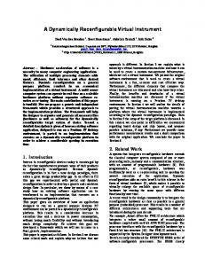
constant of the i'th parameter. (3) together with (2) constructs the basic characteristics of the scheme which is illustrated in Figure 1.
In this study, the relatively simpler adaptive control algorithm proposed in [6] is mapped to a massively parallel machine to exploit its reconfigurability. A bottom-up approach is used which starts from the configuration of processing elements and goes upwards. The algorithm can be summarized as follows: By using the Lagrange-Euler method, the inverse dynamics model of a robot arm can be obtained as: ..
.
τ = A( ξ, q ) q + B( ξ, q, q )
Figure 1: Teaching Scheme
(1) .
..
Where τ ∈Rn is the torque, n is the number of joints, q, q, q ∈ Rn are the joint positions, velocities and accelerations respectively, A ∈ Rn×Rn is the symmetric nonsingular generalized inertia matrix, B ∈Rn is the term containing the gravity, coriolis and centrifugal forces, ξ ∈R10n is the actual parameter vector.
Since (1) is linear in .
..
ξ , it can be written as
τ = H ( q, q, q ) ξ Let
Hi
Where H ∈ Rn×R10n. indicate the i'th column of 10 n
.
H . Note that .
A( ξ, q ) = Σ ξ i Ai ( q ) and B( ξ, q, q ) = B( q, q )ξ with Ai ∈ i =1
Rn×Rn, i=1,...p symmetric matrices, B∈Rn×R10n and i'th component of
ξ.
ξ i , the
The typical computation for dynamic control algorithm therefore takes the form: y = a1*a2*a3 + b1*b2*b3*b4*b5 + c1*c2*c3*c4 + e1*e2 + f1*f2*f3+ g1*g2*g3 (4) where the terms are either constants, sine and cosine function terms or joint positions, velocities and accelerations (actual and desired). A Taylor expansion of the sine or cosine series is basically a sum-of-products with about six to seven product term which itself is a special case of the equation (4). It should be noted that the equation might involve many terms when six degrees of freedom are to be supported. Therefore, an effective mapping of the equation (4) onto the FPGA is paramount for achieving an effective implementation of the algorithm.
2278
Authorized licensed use limited to: Nanyang Technological University. Downloaded on December 21, 2009 at 20:07 from IEEE Xplore. Restrictions apply.
III. COMPUTATIONAL MODEL Since equation (4) has to be evaluated in a floating-point environment, an optimum architecture for floating point addition/multiplication is required. A computational model based on the floating-point sum-of-product architecture described in [7] has been modified to allow for products of products. The concept uses a fixed computational model with multiple processing components to minimize the cost associated with development of a fully synthesised implementation. The proposed architecture is shown in Figure 2. It has three major components: the Control Unit (CU), the I/O Sub-system and the Execution Unit (EU). The CU performs the decoding of the instructions, receives the data from the I/O Sub-system, broadcasts the control and data words to the functional units for execution
and controls the execution sequence. The FPGA communicates with the external world through the I/O Subsystem. The I/O Sub-system has three I/O ports. One is linked to the associated memory (if the local memory provided by the FPGA is not sufficient) while the other two are connected to two common buses which are linked to the other FPGAs. Upon receiving the address from the CU, the I/O Sub-system fetches the operands from memory or other FPGAs and writes back the data to the local memory or broadcasts it to the common buses. To execute the robotics control algorithm, the FPGA behaves as a Multiple Instruction Multiple Data (MIMD) machine. The computation of the sine and cosine terms that appear in the computation are grouped and evaluated in parallel based on the availability of the computational clusters that are available.
Program Memory
External
Increment
3 x 8-bit Control or Instruction
24-bit
IR
PC
IN
8-bit Control/Instruction
24-bit OUT
I decode
16-bit ADD_R 8-bit
24-bit
Control Word
Data
Address Register
Control Unit
I/O Sub-System
Data
ER
ctrl signal
c+s
c+s c/s M1
Buffers c+s
M2
Match/ control Unit
c/s
Switching/ Propagation
M3
Unit
c/s
c/s M4
c/s
ctrl signal c/s
SUM Unit ctrl signal
Execution Unit Figure 2. The Architecture of the Processing model for Robotics Control
2279
Authorized licensed use limited to: Nanyang Technological University. Downloaded on December 21, 2009 at 20:07 from IEEE Xplore. Restrictions apply.
Data in the proposed model is represented using a 24-bit floating-point representation (16-bit mantissa, 8-bit excess 64 exponent). The 24-bit value received via the IR register can be a 3 x 8-bit control words or 3 x 8-bit instruction words. Control words are tagged by a '0' in InstrTag and have a fixed format of fields composed of OutTag, IdTag and AddrM. OutTag indicates whether the Propagation/Switching unit passes the result to the Sum-unit (value=0) or to the internal buffers (when multiple-multiplication is required, value=1). IdTag is a 4-bit identity tag, each bit represents one M-Unit, i.e. 0001 for unit M1. AddrM is a 2-bit tag to indicate the address mode for the associated data (00 for immediate mode, 01 for direct mode, 10 for indirect mode and 11 for buffer mode). The data words immediately follow the instruction word. For immediate mode, the data word is fetched directly from the program area. In case of direct addressing, the word contains the address of the local memory where the data is stored. Indirect address refers to a global address of a given PE and is interpreted accordingly by the bus control system. The address information directly follows the instruction word. In case of buffer mode, no address word is required since an extra buffer is satisfactory for computing products with more than one term provided that the computations are scheduled in an optimal form. IV. MAPPING THE DESIGN TO THE FPGA FPGAs have been used quite extensively in Robotics. A framework for dynamically reconfigurable robot has been proposed and implemented recently [8]. To implement the proposed architecture, we chose VHDL. VHDL descriptions of the entities are complied for both simulation and synthesis. Then, the behavioral and functional simulation is accomplished. Once the simulation targeting the FPGA is performed satisfactorily, the entities are synthesized and optimized for the target FPGA technology. The difficulties of operating on a reconfigurable platform has been overcome by first defining a fixed computational model with multiple processing components and then by using the FPGAs local memory for storing micro-instructions to drive the parallel processors. The performance of the unit depends on the target FPGA technology. In some cases full summation units are provided. Independent of the underlying technology, the proposed model achieves high performance combining two well-known techniques in a single platform: instruction parallelism/pipelining and avoidance of carry propagation while evaluating a sequence of sum of products.
summation during the multiplication cycles. A carry-save adder (Sum-Unit), capable of mantissa alignment, correctly positions products with respect to the current carry-save sum. An exponent component is associated with each unit and shifting capabilities are incorporated into the carry-save multiplier to achieve the mantissa alignment for upcoming summation. Carry propagation in M-Units is avoided except when a product with multiple terms has to be evaluated and the final result is required in a non-redundant form. Four such multipliers can be used to achieve the optimal performance. The Match/Control Unit is responsible for fetching the control+data word from the bus. It interprets the control words to initiate the transfer of data to the Carry-Save Multipliers for multiplication or simply ignores the data. The carry-save results from the multiplier are output to the switching/propagation unit. For a multiplication with more than two terms, the unit transforms the carry-save result to a non-redundant form and temporally stores on the buffer for the upcoming multiplication. Otherwise, the carry-save result is transferred to the sum-unit for summation. The extent of the parallelism/pipelining inherent to the proposed model can be best evaluated by examining Table 1. Table 1 shows the code generation strategy used in generating a machine sequence for the FPGA to execute Equation (4). During the allocation process, as soon as an intermediate result becomes available, it is paired with a buffered intermediate result (if any) or with a new variable. The notation for the feedback result is for code generation purposes. In the actual implementation, due to the choice of the allocation strategy, a single buffer is sufficient since there could only be one intermediate result waiting to be operated on. If no intermediate result is available, then two new variables are allocated to maximize the use of the hardware. The CU fetches the instructions from the program memory with concurrent decoding and execution of the previously fetched instruction. The PE receives a 24-bit value in the register IR at the beginning of each machine cycle. This value represents three 8-bit instructions or control words. When an instruction is encountered, the PE obeys the instruction. In the case of a control word, the CU receives data from the I/O Sub-system and combines it with the control word to form the execution word for the M-units (M1 to M4). The result of the Sum-unit is achieved through one single instruction which terminates the computation for the equation by allowing carry propagation. The result is sent to the I/O Sub-system and the Sum-unit is initialized for further computations. Otherwise, the Sum-unit receives the data in carry-save form from the M-units and performs the summation to the existing internal value.
The basic building block of the EU is a carry-save multiplier (M-Unit) with built-in mantissa alignment for the
2280
Authorized licensed use limited to: Nanyang Technological University. Downloaded on December 21, 2009 at 20:07 from IEEE Xplore. Restrictions apply.
M Unit
Load Time
M1 M2 M3 M4 M1 M2 M3 M4 M1 M2 M3 M4 M1 M2 M3 M4
0 2 4 6 8 10 12 14 16 18 20 22 24 26 28 30
Start Execute Time 2 4 6 8 10 12 14 16 18 20 22 24 26 28 30 32
Execute Complete Time 10 12 14 16 18 20 22 24 26 28 30 32 34 36 38 40
Result Ready Time 12 14 16 18 20 22 24 26 28 30 32 34 36 38 40 42
Variable Allocated
Feedback Result
b1, b2 b3, b4 c1, c2 c3, c4 a1, a2 e1, e2 f1, f2 g1, g2 I1, I2
I1 I2 I4 I5 I6
Additional Time For Feedback 2 2 2 2 2
I7 I8 I3
2 2 2
Flag for Last Multiplication of a Product Term
marked
I4, I5 I6, a3
marked marked
I7, f3 I8, g3 I3, b5
marked marked marked
TABLE 1. CODE GENERATION STRATEGY
V. FAULT TOLERANCE AND RECONFIGURATION. Fault tolerance and self repair is a major area of research in robotics [9]. It is especially relevant when robots are operating in hazardous areas or in space. The fault tolerance aspects discussed in this paper are limited to self repair in the electronic domain. In general, FPGAs have a great deal of potential for fault tolerance [10]. The issue is well understood at CLB level. Emmert and Bhatia [11] use partial reconfiguration and incremental routing and while Hancek and Dutt [12] proposes node covering for achieving fault tolerance. Techniques have also been developed to examine and isolate defective parts of the FPGA similar to marking as bad blocks the blocks of the disc that are not operational. When a computational module of the proposed architecture is diagnosed to be faulty, the functionality that is delivered by that module has to be delivered elsewhere on the same chip. In fact this is similar to a memory miss when one is trying to access data on a hard disk. The choice of optimal block size for the virtual store management is similar to the decision that has to be made about size of the FPGA area that will be reconfigured. For our architecture, the module is a basic subsystem of the processing unit. The objective is to ensure that a faulty section of a chip can be isolated without incurring a massive cost by discarding parts that are still working. The system developer has to make choices between different sizes.
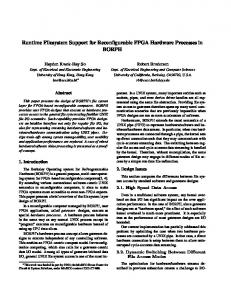
Figure 3 shows the issues associated with the mapping of hardware implementations of tasks to FPGA hardware. Considerations include provision of communication paths between related tasks and choice of optimal grid structure. In this Figure, a rectangular structure is depicted. Small granularity minimizes fragmentation but may cause the tasks to be too small. VI. CONCLUSION The computational model targeted for an FPGA described in this paper achieves high performance combining two wellknown techniques in a single platform: instruction parallelism/pipelining and avoidance of carry propagation while evaluating a long sequence of sum of products. Using a stored program, a reconfigurable platform is exploited without requiring full synthesis for a given FPGA configuration. The modular approach also leads itself to achieving fault tolerance, by allowing faulty components of the processing unit to be allocated on the fly to available parts of the FPGA. Future work could ease the burden of programming the processing unit by including automated code generation software, which uses an expression compiler and an assembler similar to the concepts presented in [13].
2281
Authorized licensed use limited to: Nanyang Technological University. Downloaded on December 21, 2009 at 20:07 from IEEE Xplore. Restrictions apply.
Figure 3: Hardware implementation of tasks to FPGA.
REFERENCES: [1] S. S. Erdogan, “Programming a Reconfigurable Platform for Neural Network Simulations”, 6th IASTED International Conference on Signal and Image Processing, Honolulu, Hawaii, pp.614-618, Aug. 23-25, 2004. [2] S. S. Erdogan, “Programming a Reconfigurable Platform for Neural Network Simulations”, Proc. of the IASTED International Conference on Circuits, Signals and Systems, Clearwater Fl, USA, Nov. 28 - Dec. 01, 2004. [3] I. Sahin, C. S. Gloster and C. Doss. "Feasibility of FP Arithmetic In Reconfigurable Computing Systems", MAPLD on Adaptative Computing, Vol. 3, September 2000. [4] Eylon Caspi, et al, “Stream Computations Organized for Reconfigurable Execution: Introduction and Tutorial”, Proc. 10th Int. Conf. on FPL and Applc.”, Aug. 28-30, 2000. [5] Lehn, David, Rhett, D. Hudson and Peter M Athanas, "Framework for architecture-independent run-time reconfigurable apps", Proc. SPIE, Boston, MA, Nov. 2000. [6] T. Tunali, A Neural Network Approach for Robust Dynamical Control of Robot Manipulators. Proc. of the IEEE International Symposium on Circuits and Systems, Chicago, Illinois, 1993, pp. 2450-2453. [7]
S. S. Erdogan and Abdul Wahab, Hierarchical Decomposition Model for Reconfigurable Architectures.
Proc. SPIE Photonics East ‘96 Symposium, Boston, MA, 1996, pp. 141-151. [8] A. Upegui, R. Moeckel, E. Dittrich, A. Ijspeert, and Sanchez E. “An FPGA dynamically reconfigurable framework for modular robotics”. Procedings of the 18th International Conference on Architecture of Computing Systems 2005 (ARCS'05). VDE Verlag, Berlin, 2005. [9] S. Murata, E. Yoshida, A. Kamimura, H. Kurokawa, K. Tomita, and S. Kokaji, "M-TRAN: Selfreconfigurable modular robotic system," IEEE-ASME Transactions on Mechatronics, vol. 7, pp. 431-441, 2002. [10] B. Culbertson, R. Amerson, R. Carter, P. Kuekes, G. Snider, “The Teramac Custom Computer: Extending the Limits with Defect Tolerance”, Proc. IEEE Int. Symposium on Defect & Fault Tolerance in VLSI Systems, Nov. 1996. [11] J M Emmert, Dinesh Bhatia, “Partial Reconfiguration of FGPA Mapped Designs with Applications to Fault Tolerance and Yield Enhancement”, Proc. 7th Workshop on FPL and Applications, pp. 141-150, Sept. 1997. [12] F. Hanchek and S. Dutt, "Methodologies for Tolerating Logic and Interconnect Faults in FPGAs'', IEEE Trans. Computers, Special Issue on Dependable Computing, pp. 15-33, Jan. 1998. [13] S. C. Goldstein, H. Schmit, M. Budiu, S. Cadambi, M. Moe, and R. R. Taylor, "PipeRench: A reconfigurable architecture and compiler," Computer, Vol. 33, pp. 70-77, 2000.
2282
Authorized licensed use limited to: Nanyang Technological University. Downloaded on December 21, 2009 at 20:07 from IEEE Xplore. Restrictions apply.