responses, 3 dipoles were placed in the insular area to imitate auditory evoked responses, 2 dipoles were placed in the frontal base area to imitate orbital.
Effect of conductor model on source localization in case with source at the frontal base – A realistic-shaped phantom study Y. Kaneko1, M. Yumoto2, H. Shigeto3, S. Ohtomo1, O. Saito4, and Y. Takashima5 1
Department of Neurosurgery, 3 Department of Neurology, 4 Department of Psychiatry, and 5 Department of Laboratory Medicine, National Center Hospital for Mental, Nervous and Muscular Disorders, NCNP, 1878551 Tokyo, Japan; 2 Department of Laboratory Medicine, University of Tokyo, 113-8655 Tokyo, Japan
1
Introduction
In the clinical application of magnetoencephalography ( MEG ) to epilepsy, cases in which epileptic discharges are in the temporal base area or the frontal base area are relatively common. These regions are not spherical and the spherical model as a conductor model may not be suitable rigorously. Source localization by MEG was once thought to be accurate due to little influence of volume current but importance of volume current began to be emphasized recently [1]. Software using the realistic headshape model as a conductor model is available commercially now. In order to evaluate commercially distributed software from the clinical point of view, authors conducted a realistic-shaped phantom study and report the efficacy and limitations of the realistic headshape model especially in cease with sources in the temporal base area and the frontal base area.
2
Methods
2.1
Phantom
A model skull for medical education was utilized to make a realistic headshape phantom. Orbital apexes and cranial canals were sealed to contain saline solution. Ten artificial dipoles were made by twisted pair of insulated copper wires (ø = 0.3 mm) whose end segments formed the top of a "T" with tips exposed [2]. Acrylic resin 10-millimeter cubes were utilized to make uniform artificial dipoles and the cubes were drilled to avoid the obstruction against the volume current. Three dipoles were placed in the central area to imitate somatosensory evoked responses, 3 dipoles were placed in the insular area to imitate auditory evoked responses, 2 dipoles were placed in the frontal base area to imitate orbital discharges and 2 dipoles were placed in the temporal base area to imitate hippocampal and parahippocampal discharges. In fixing dipoles, acrylic resin rods were used on demand. Twisted parts of the wires inside the phantom were arranged
to orient radially and the T-shaped segments were arranged to orient tangentially. A set of 125 axial CT slices (1.5-millimeter thickness) of the phantom was obtained and was used for measuring artificial dipole locations and constructing realistic headshape models.
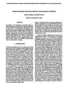
Figure 1: Realistic headshape phantom in the process of manufacturing.. 2.2
Measurements
Auditory stimulation generator was used for producing electrical current. Tone burst (100 Hz, 100 msec duration) current was applied to artificial dipoles with its strength regulated so that the moment of the current was between 100 and 150 nAm. Inter-stimulus-interval was 333 msec and 50 epochs were averaged. For each dipole, two sessions were recorded. The recording passband was 0.1-400 Hz, with a sampling rate of 1,000 Hz. Epochs with MEG signal exceeding 3,000 fT/cm were excluded from averaging. Measurement was performed in a magnetically shielded room (NKK Plant Engineering Co., Japan) with a 204-channel whole-head neuromagnetometer (Neuromag Ltd., Finland) which has 102 units
comprising 2 orthogonal planar gradiometers. The position of the phantom with respect to neuromagnetometer was measured by 4 indicator coils attached to the phantom. The locations of 4 coils were determined with an Isotrak 3D-digitizer (Polhemus Inc., USA) prior to MEG measurement. 2.3
Data analysis
Averaged waveforms were digitally filtered with a high-pass of 5 Hz to remove DC shift. Ten equivalent current dipoles (ECDs) were calculated at peak latency of tone burst waveform for each session utilizing all 204 channels and 20 ECDs were obtained for each artificial dipole. In calculating ECDs, 3 spherical conductor models and 3 realistic headshape models (one-layer model) were employed for dipoles placed in the frontal base area and the temporal base area. Six conductor models consist of the sphere fitting to the inside of the skull totally (whole_head), the sphere fitting to the inner surface of the skull near the dipole (local_large), the sphere fitting to the inner surface and the base part of the skull near the dipole (local_small), the mesh generated from the inner surface of the skull with averaged edge length of 20 mm (434 triangles; large_mesh), the mesh with averaged edge length of 10 mm (1,684 triangles; medium_mesh) and the mesh with averaged edge length of 5 mm (6,098 triangles; small_mesh). The whole_head model and the medium_mesh model were also employed for dipoles placed in the central area and the insular area. All analysis was performed with the standard software provided by Neuromag Ltd. ECDs were evaluated by the averaged errors of locations from the accurate locations measured by CT and by averaged goodness of fits (GoFs).
3
Results
3.1
Dipoles in the central and the insular area
Three dipoles in the central area ( SEF1, SEF2, and SEF3 ) and 3 dipoles the insular area ( AEF1, AEF2, and AEF3 ) were utilized for the verification of the phantom and for examining the effect of the conductor model for general sources. SEF1, SEF2, and SEF3 located superficially with SEF1 lower and SEF3 upper. AEF1 located superficially and AEF3 deeply. The errors of the localization of the ECDs for superficial dipoles ( SEF1, SEF2, SEF3 and AEF1 ) were 2.2 to 5.5 mm when whole_head model was employed as a conductor model. The lengths of the dipoles were 10 mm and the accuracy of the ECDs was acceptable. GoFs were 93.9 to 96.8 % because
of large magnetic fields. The error of the localization of the ECDs for AEF3 was 10.0 mm and GoF was 78.8 when whole_head model was employed, which was due to small magnetic fields. When medium_mesh model was employed, the errors of the localization and GoFs made little difference for superficial dipoles, however, the errors of the localization for AEF3 decreased to 4.1 mm although GoF was similar. a)
b)
c)
Figure 2: Conductor models employed in the calculation of ECDs. Spherical conductor models for dipoles placed a) in the frontal base area and b) in the temporal base area are indicated by the yellow circles. From left to right, whole_head, local_large and local_small. c) Realistic headshape models. From left to right, large_mesh, medium_mesh and small_mesh. Table 1: The errors of the localization of the ECDs and GoFs for dipoles placed in the central area and the insular area. Calculation was performed by using both spherical model ( whole_head ) as well as realistic model ( medium_mesh ). whole_head Dipole Error [mm] GoF SEF 1 5.0 96.8 SEF 2 5.9 96.1 SEF 3 5.0 96.3 AEF 1 2.2 93.9 AEF 2 5.3 92.0 AEF 3 10.0 78.8
medium_mesh Error [mm] GoF 3.5 97.3 4.2 96.6 5.0 96.5 4.2 94.2 3.8 92.9 4.1 80.1
3.2
Dipoles in the frontal base and the temporal base area
Six conductor models (whole_head, local_large, local_small, large_mesh, medium_mesh and small_mesh) were adopted in order to evaluate the effect of the conductor model on the localizatiom of ECDs for 2 dipoles in the frontal base area (FB1; upper and FB2; lower) and 2 dipoles the temporal base area (TB1; medial and TB2; lateral). Among spherical models, whole_head was best in both the errors of the localization of the ECDs and GoFs. However, the errors were 6.6 to 17.1, which was worse than the case with superficial dipoles in the central and insular area. GoFs were low (66.3 to 74.9 %) for the dipoles in the temporal base area, which was the reason for imprecise localizations. In case with the dipoles in the frontal base, although GoFs were high (94.5 to 94.9 %) because of the superficial dipoles, the errors were also large. All ECDs for these 4 dipoles tended to be localized in the more superficial point than the actual point. Concerning realistic models, results was different between the dipoles in the frontal base area and those in the temporal base area. For the dipoles in the temporal base area, all the realistic models provided more precise localization than the spherical models. Small_mesh model was the best as was predicted, however, medium_mesh led to acceptable ECDs although GoFs were similar. In case with the dipoles in the frontal base area, the errors were still more than 5 mm (6.5 to 8.3 mm for FB2 and 11.6 to 12.7 mm for FB1) and little difference was found between large_mesh and small_mesh.
4
Table 2: The errors of the localization of the ECDs and GoFs for dipoles placed in the frontal base and the temporal base area. Calculation was performed by using 3 spherical model as well as 3 realistic models. Dipole
Wholel_head Error GoF
spherical model local_large Error GoF
local_small Error GoF
FB1
16.1
94.5
76.7
58.7
56.9
62.0
FB2 TB1 TB2
7.5 17.1 6.6
94.9 66.3 74.9
6.6 17.4 12.7
94.5 57.4 72.3
62.1 1166.5 162.5
33.2 21.5 20.9
realistic model Dipole
large_mesh Error GoF
medium_mesh Error GoF
small_mesh Error GoF
FB1
12.7
96.1
11.7
96.6
11.6
96.7
FB2 TB1 TB2
6.5 7.8 5.4
94.8 70.9 76.7
7.9 5.8 2.7
95.5 71.7 77.0
8.3 4.2 2.7
95.5 72.9 77.4
a)
b)
Discussion
The comparison between the spherical models and the realistic headshape model has been reported with phantom approach and simulation approach [3, 4]. These studies showed superiority of the realistic headshape model over the spherical models, however, difference was trifling. In these studies, dipoles located relatively spherical part of the skull, which might be the reason of the results. In the present study, we intended to answer the question how useful the spherical model is for sources in the temporal base area and the frontal base area, which are relatively common in the patient with epilepsy. We also wanted to know the best conductor model among spherical models. Our results for the dipoles in the temporal base area ( TB1 and TB2 ) suggested the efficacy of the realistic headshape model. Superiority of the realistic headshape model was also noticed for AEF3.
Figure 3: Superimposed ECDs for a) FB2 and b) TB1. Dipoles presented by pink triangles were calculated with a spherical model ( whole_head ) and dipoles presented by yellow squares were calculated with a realistic model ( medium_mesh ). The actual dipole was indicated by the green bar( dot ). a) Left; sagittal view, right; axial view. b) Left; coronal view, right; axial view.
The common feature of these dipoles are deep location from the surface of the skull, therefore, it is concluded that the realistic headshape is effective for deep seated dipoles. On the other hand, the realistic headshape model is not necessary for superficial dipoles. The realistic headshape model requires much time and when we want to obtain ECDs rapidly with the spherical model, whole_head model is the best choice in general. The reason for large error for the dipoles in the frontal base area ( FB1 and FB2 ) is not clear. Previous study reported that localization errors depended on the dipole position in the brain [5]. Surrounding structures like acrylic resin cubes and bars might interfere the volume current. Our study may suggest the limitation of the realistic headshape model.
3.
References
5.
1. M. Fuchs, H.A. Wishmann, M. Wagner, and A. Theißen, “Performance of realistically shaped boundary element method volume conductor”, in Recent Advances in Biomagnetism, T. Yoshimoto, M. Kotani,
2.
4.
S. Kuriki, H. Karibe, and N. Nakasato, Eds. Sendai: Tohoku University Press, 1999, pp. 193196. T. Yamamoto, S.J Williamson, L. Kaufman, C. Nicholson, and R. Llinas, “ Magnetic localization of neuronal activity in the human brain”, Proc. Natl. Acadd. Sci. 88, 8732-8736, 1988. R.M. Leahy, J.C. Mosher, M.E. Spencer, M.X. Huang, and J.D. Lewine, “ A study of dipole localization accuracy for MEG and EEG using a human skull phantom”, Electroenceph clin Neurophysiol 107, 159-73, 1998. S.P. van den Broek, F. Reinders, M. Donderwinkel, and M.J. Peters, “ Volume conduction effects in EEG and MEG ” , Electroenceph clin Neurophysiol 106, 522-34, 1998. A. Crouzeix, B. Yvert, O. Bertrand, and J. Pernier, “ An evaluation of dipole reconstruction accuracy with spherical and realistic head models in MEG ” , Clinical Neurophysiology 110, 2176-88, 1999.