the permeability and resolved excitation characteristics of a composite core formed utilizing N independent cores of M different materials. I. INTRODUCTION.
IEEE TRANSACTIONS ON MAGNETICS, VOL. 26, NO. 6, NOVEMBER 1990
3086
Error Estimation of Current Transformers Using Single or Composite Cores of Ferromagnetic Materials P. SANKARAN, V. JAGADEESH KUMAR,
Abstract-A program has been developed to estimate the errors of current transformers employing single or composite cores of ferromagnetic material. In addition, the program enables determination of the permeability and resolved excitation characteristics of a composite core formed utilizing N independent cores of M different materials.
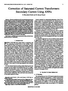
I. INTRODUCTION IMITS on the permissible errors of current transformers (CT's) for measuring applications are specified by standards such as the ANSI/IEEE (257.13-1978 [ l ] or the IEC 185-1986 [2]. Extended range current transformers are to comply with these limits over a wider operating range. Some standards such as the AS 16951986 [3] prescribe limits in the variation of errors over certain ranges of current. For example, a CT complying to an accuracy class of 0.5 must have a variation in ratio error within 0.4% between 5 and 10% of the primary current. The design process involves the choice of proper core dimensions and material to meet the given specifications. It is often necessary to use composite cores [4] with two different materials, one of which is nickel iron, to comply with design requirements. Such occasions arise, for example, 1) when specifications prescribe a limit on the variation in errors over a wide operating range; 2) to meet the requirements of a high short-time current rating (40 kA for 1 s)/burden at low primary currents ( < 50 A), as in the case of medium voltage switchgear, 3) when the necessity of a low instrument primary limit current arises. Composite cores are formed by either choosing the same inner and outer diameters for the two toroids or by positioning the core having better properties as an inner toroid. Sandwiching one material between two other toroids is also possible, as shown in Fig. 1. The design process will be simplified and rendered more efficient if the envisaged CT is simulated and studied, thereby providing the designer a free hand to experiment with various possible combinations in arriving at the optimum design.
AND
V. JAYASHANKAR
core 1
/
,Core 1
Core2
L
I
Manuscript received October 6, 1989; revised June 12, 1990. The authors are with the Department of Electrical Engineering, Indian Institute of Technology, Madras 600 036, India. IEEE Log Number 9038735.
(C)
Fig. 1. Construction of composite cores.
With this end in view, the PC-compatible program, ERCOMPCT, has been developed to estimate the errors of CT's containing either single or composite cores of ferromagnetic material. The program provides an output either on an X-Y plotter or on a line printer. 11. DESCRIPTION OF THE PROGRAM For each core material, data, either measured or made available by the manufacturer, are stored in the form of a sequential file containing B (peak flux density in teslas), H , (rms watt loss in amperes per meter) and H, (rms magnetizing in amperes per meter). A maximum of 50 points can be stored for each core. The program calculates intermediate values using the relation
log B
=
K x log H
+ C,
which provides a well accepted fitting [5]. The computer program developed first predicts the overall effective excitation characteristics when N cores of M different materials are stacked in any of the fashions depicted in Fig. 1'. The flowchart of Fig. 2 illustrates the process of calculation, which is along the lines of Jenkins [6]. H for the composite core is taken to vary from 0.1 to 50 A/m. For a chosen value of H, the corresponding flux density B in each core is determined via the core data files. The induction in core of material 1 is taken as a reference phasor, and that in every other core is expressed as compo-
0018-9464/90/1100-3086$01 .OO 0 1990 IEEE
L'i.
.
f.
~
&-
3087
SANKARAN e? al.: ERROR ESTIMATION OF CURRENT TRANSFORMERS 2
60
ENTER
H =0.001
I
I
-
?stlo
250 / 5 C o r e No
I 2
1.5
A. OD 90 90
15
ID 60 60
VA.
.8 HT 20 20
.
~
.
f
Material TRAFOPERM N2 PERMAX
1
A5
30
.5
15
? tan W N )
HytcW)
5
i
-
d
J
20 Q
100 0
I2
ratio error L
-. 5
-15
-I
-30
-1.5
-45
T -2
Fig. 2. Subroutine for overall excitation characteristics.
nents in phase and in quadrature to the reference. The equivalent flux density of the composite core is found from the phasor sum of the fluxes in the different cores. H,,, and H, for the composite core can now be determined. Once the excitation characteristics of the composite core are determined for a particular proportion of materials, the errors of a CT with specified ratings are easily estimated [6]. The developed program provides as output the ratio and phase errors of a CT of preliminary design, either on an X-Y plotter using GP-GL commands with a Centronics interface or on an 80-column printer. If required, the relative permeability of the composite core as a function of B or H is made available as additional output. The program also generates data files for composite core characteristics as well as error characteristics that can be exported to standard graphing softwares like GRAPHER, HG, and SLIDE. The program has the advantage of quickly amving at an optimum design of a composite core CT to meet given IEC specifications.
.
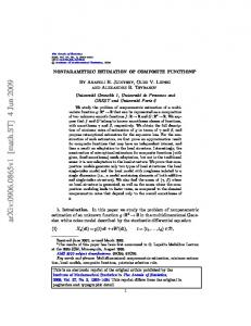
111. VALIDATION A model 2 5 0 / 5 , 5 VA, CT has been designed and constructed using a 50% TRAFOPERM N2 (iriented steel)
-60
Fig. 3. Error characteristics of a current transformer.
and 50% PERMAX (Ni-Fe) produced by Vacuumschmelze GmbH, West Germany. Its ratio and phase errors as determined with the developed program and plotted on a GRAPHTEC MP 3300 X-Y plotter are shown in Fig. 3. The points indicate the actual errors measured on the CT with a comparison bridge. The deviation in the errors from the predicted values are of the same order as the spread of the magnetic properties of cores belonging to a particular batch.
REFERENCES [ 11 ANSI/IEEE C57.13-1978. “Standard requirements for instrument
transformers,” [2] I.E.C. 185-1986, “Current transformers.’’ [3] Australian Standard AS 1695-1986, “Current transformers for measurement and protection.” [4] M. Soinski, W. Bulica, K. Cieslewicz, and J. Szczyglowski, “Current transformer with cut core made of metallic glass,” IEEE Trans. Magn., vol. 24, no. 2, pp. 1871-1872, Mar. 1988. [5] J. Fischer and H. Moser, “Die Nachbildung von Magnetisierungskurven durch einfache algebraische oder transzendente Funktionen,” , Archivfur Elektrotechnik, vol. XLII, pp. 286-299, 1956. [6] B. D. Jenkins, Introduction to Instrument Transformers, London: George Newnes, 1967.
P. Sankaran was born in hdukkottai, Tamizhnadu, on September2, 1939. He received the B.E. degree in electrical engineering and the MSc. (Eng.) degree in electrical machine design from the University of Madras in 1960 and 1961, respectively. He received the Ph.D. degree in electrical engineering from the Indian Institute of Technology, Madras, in 1972.
I
3088
IEEE TRANSACTIONS ON MAGNETICS, VOL. 26, NO. 6, NOVEMBER 1990
He was a Senior Fellow of the Technical Teachers’ Training Programme of the Government of Indian from 1961 to 1963. In July 1963, he joined the Electrical Engineering Department of I.I.T., Madras, where he is presently a Professor. His teaching and research interests are in the areas of electrical networks, machines, measurements,,,and instrumentation. He is currently at the Institut fiir Elektrische Energie Ubertragung, Stuttgart, West Germany on a Visiting Fellowship.
He is currently working in the Department of Electrical Engineering, Indian Institute of Technology, Madras as a Lecturer. His interests are in the areas of measurements, instrumentation, and signal processing.
V. Jagadeesh Kumar was born in Madras, India, on July 21, 1956. He received the B.E. degree in electronics and telecommunication engineering from the University of Madras in 1978 and the M.Tech. and Ph.D. degrees from the Indian Institute of Technology, Madras, in 1980 and 1986, respectively .
V. Jayashankar received the B.Tech. degree in electncal engineering from the Institute of Technology, Banaras Hindu University, in 1982. He is currently working toward the M.S. degree in the Department of Electrical Engineering, Indian Institute of Technology, Madras, India. He worked as a design engineer in the field of instrument transformers up to 1986. His interests are in the field of instrument transformers and switchgear.