has a lot of advantages, therefore building network systems may improve. But there are still problems like low security, transfer delays and packet losses. In this.
International Journal of Control, Automation, and vol. 4, no. 1, pp. 63-69, February Ethernet Algorithm forSystems, Building Network Integration Using TCP/IP2006
63
Ethernet Algorithm for Building Network Integration Using TCP/IP Kyung-Bae Chang, Il-Joo Shim, and Gwi-Tae Park Abstract: Problems like poor security, transfer delay or packet loss occur while building network systems that are applied with TCP/IP integrate with data network systems. To solve this problem, this paper proposes the Separated Ethernet, which can give priority to the system, and by using the OPNET Modeler simulator, we will verify its performances. Keywords: Building network, control network, ethernet, building integration.
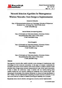
1. INTRODUCTION Recently, building industries and building management industries have made great developments. Many facilities and instruments are installed to one building, and the cost for energy and management has been going up. Because of this, a more economic managing, and efficient integration system was required. Therefore the buildings are developing into forms of intelligent building systems. To obtain efficient management and energy preservation, intelligent building systems like these need to integrate the facilities and instruments. For integrated use, information between each of the facilities must be shared, and in order to do so, a network is required. In a building, networks are divided by its facility’s functions into control networks and data networks. At present, building automated systems (BAS) use various control protocols provided by its manufacturers. And the control networks and data networks are completely separated, as shown in Fig. 1, for security reasons. In order to integrate these independent networks, a separate network device is required, and the network structures must be overlapped according to their types. Therefore a spec shared, open protocol is inevitable for an integrated and efficient system. Integration has been applied on actual buildings, and research for a more compatible integration is in progress. Also, research on the use of control open protocols, like LonWorks and BACnet, for more efficient integration is in progress [1,2]. Among these researches, there are studies on the use of Ethernet, which is widely used as TCP/IP, on the control network [3-5]. As Ethernet and TCP/IP are widely
used throughout Korea, and almost every building has TCP/IP installed, many existing building’s network systems integrate the lower protocols by using the upper Ethernet and TCP/IP. Accordingly, in order to solve the problems of applying TCP/IP to the building control network, research on the possibilities of integrating the entire building control system into TCP/IP is in progress [6,7]. This paper proposes the Separated Ethernet, which can integrate the entire network in the building into TCP/IP protocol, and verifies its performance with a network simulator. The proposed Ethernet has been developed to be compatible with the existing Ethernet. Also it is developed to use the character of both, the data network, which has random traffic on random moments, and the control network, which has low traffic on regular time. The proposed method has less wiring, convenient management and better flexibilities, because integrating and expanding the entire control network system becomes easier and the integration between the control network and data network becomes possible. Control Network SI Server
L2 Hub
Repeater HVAC Server
Power
Light Server
Server
DDC
Web Server
Internet
DDC
DDC
DDC
DDC
DDC PC `
__________ Manuscript received February 22, 2005; revised September 29, 2005; accepted October 10, 2005. Recommended by past Editor-in-Chief Myung Jin Chung. Kyung-Bae, Il-Joo Shim, and Gwi-Tae Park are with the School of Electrical Engineering, Korea University, 1, 5-ka, Anam-dong, Sungbuk-ku, Seoul 136-701, Korea (e-mails: {lslove, ijshim, gtpark}@korea.ac.kr).
Clustering
PC `
PC `
MDF PC
Router
`
PC `
PC `
FireWall NMS
MDF
Data Network
Fig. 1. The control networks and data networks are completely separated in building network system.
64
Kyung-Bae Chang, Il-Joo Shim, and Gwi-Tae Park
1.1. Building network systems Building network systems can be classified into two groups, the control network and the data network. The control network is a network where communication between, a facility needed in a building automated system and the server that controls them, are made. Open protocols like BACnet, LonWorks are used in the control network. The data network is an internet connected network, which is capable of services like www, ftp, telnet or e-mail. TCP/IP is the most wellknown open protocol for the data network. The features of both the networks are as shown in Table 1. 1.2. The advantages of integrating the data network and control network If the two networks integrate into one, an integrated management of all the facilities and machinery in the building will become possible. Also, by this, a more flexible network structure becomes possible, and the amount of wiring reduces. With the low amount of wiring, basic building costs become lower, and the modification and expansion of the network becomes mush easier. If there are two separate networks, the gateway Web Server must transfer information between the networks, and therefore the gateway must maintain a center concentrating form. As all the information attempts to go through this gateway, the flow of information becomes clogged. However if the two networks are integrated, installation according to the amount of data transfer becomes possible. And therefore the efficiency of the web increases. Also, because the Web Server takes dispersive forms according to its purpose, the data clogging problem can be solved. The cost reduces as well, because of the lower requirements of the Web Server. 1.3. The problem that arises when the control network integrates with the data network. Control facilities become exposed to virus, cracking and malignancy codes when the control network
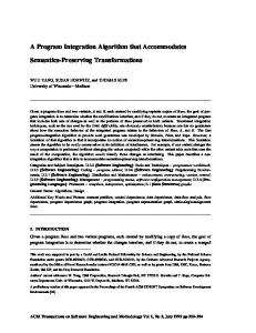
integrates with the data network, which is connected to the internet. Control facilities and devices require higher levels of security than the data network, because they have direct and physical relationships with important users. Also, due to the importance of the control information data in the control network, even a little loss can be crucial. Therefore, in order to satisfy the control network’s standards, reliable transmission and transmission delay between the transmitter and receiver is required [10]. If the two networks are integrated and there is a lot of traffic on the data network system, collision and delays occur during the packet transmissions. And if a lot of collisions occur, there may be packet loss. This is the biggest problem with the control network [8,11]. 1.4. The possibility of the integration of data network and control network. The integration of data networks and control networks has a lot of advantages, therefore building network systems may improve. But there are still problems like low security, transfer delays and packet losses. In this paper, we are trying to find a solution to this matter, and will seek its possibilities. The first problem is security. Security problems occur because of the connection with the internet. To solve this problem, the connection to the internet must be disconnected, and the facilities must be watched over carefully with a continuous security policy. However, if the two different network systems integrate, the two networks become connected physically. Therefore we propose the method of dividing the two networks logically. Physically, the two networks share a same bus line, but the transmission in bus line is sent in two separate packets. This is how we divide the data packets and control packets. Fig. 2 shows a logically divided host. On the OSI 7 Layer, Layer1 and Layer2 is connected to a single bus physically, but Layer3 and its upper layers are divided
Table 1. Differences between control network and data network. Amount of information Transfer frequency Delay time
Purpose of use
HOST
Data network Much information
Control network Little information
Data Network
Control Network
Application
Application
TCP, UDP
TCP, UDP
Irregular
Regular
IP
IP
Non real time
Real time Feedback information for control, commands between nodes, and optimized data.
Handling documents or high volume data on a computer or printer.
Enhanced Ethernet Que
Ethernet Controller
Que
LAN BUS
Fig. 2. The logically divided host.
Ethernet Algorithm for Building Network Integration Using TCP/IP
in two, and are received from the Ethernet by the use of two Queues. The frames that transfer through the bus line are transmitted in two divided networks. The second problem is transmission delay and packet loss, which is an important element in the control network. This problem can be solved by giving priorities to the control network. In this method, priorities are given to each of the Layers on the OSI 7 Layer. By giving a high priority of the use of bus to Layer1 and Layer2, the control network’s delay becomes a minimum and packet loss does not occur. If priority is given to the control packet by L3 switch Hub and Gateway, which is in layer3 of the OSI 7 Layer, the network layer, transmission delay and packet loss become minimized to the control packet standard. This paper proposes an algorithm, which can give priorities to IEEE 802.3 standard, which is in charge of layer1 and layer2, in a TCP/IP applied building integration control system. A Separated Ethernet with two different upper layers is designed for logical dividing. By the use of this Separated Ethernet, integration of the data network and control network is presented. Also, the performances and behaviors of this designed Separated Ethernet can be verified by simulation.
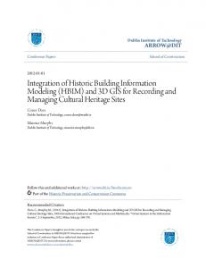
2. SEPARATED ETHERNET 2.1. Dual Queue structure and Queue Priority In building network systems, security is improved by integrating the two networks logically. We propose a method, which has independent upper layers of the control network and data network for improved security. Fig. 3 shows a dual structure Queue. If the data network’s Queue is disabled, and the data network frame is received from the Separated Ethernet, as the data is not transmitted to the upper layers, malignancy codes and virus’s attacks have no effect on the station. If there is the same data in both the data network’s and control network’s Queue, priority must be given to the
Control Network
Data Network
Enhanced Ethernet Que
Ethernet Controller
Que
LAN BUS High Priority
Low Priority
Fig. 3. The dual structure Queue and Priority.
65
control network by extracting, fragmentation and transmitting the data from the control network. 2.2. Backoff Priority Not like the MAC protocols that act in order, like Token Bus or Token Ring, Ethernet is a competitive MAC protocol, which gives priorities according to its mechanism. Ethernet gives priority to the station that attempts transmission first, and if a collision occurs by transmission delay or by transmitting at the same time, priority is decided by a BEB (Binary Exponential Backoff) algorithm. If a collision occurs, the station stands by for a random time and re-transmits. We will study how this process happens. When a collision occurs, time divides into discontinuous slots, each slot having the same length as the worst round trip transmission time. In order to receive the longest pass under regulation by the IEEE standard 802.3 (2.5km, 4 repeaters), slot time is fixed at 512 bit time, or 51.2 us. After the first collision, each station waits 0 or 1 slot times before attempting again. If two stations collide and the two stations select the same number, another collision occurs. After the second collision, each station selects a number between 0,1,2 or 3 and stands by for an equal slot time as the selected number. Now, the probability of another collision happening by selecting a same number is 0.25. If a third collision occurs with these possibilities, the section of slot time selection is between 0 and 23-1. Generally, after i times of collisions a random number between 0 and 2i-1 is selected, and the same number of slots pass. However, after 10 collisions the random section is fixed to the maximum value, which is 1,023 slots. After 16 collisions, the controller gives up and sends an abandonment signal to the computer. Afterwards recover process is up to a more upper level. This algorithm, which is called a Binary exponential backoff, has been selected to dynamically receive the number of stations to transmit. If the random section to every collision is equally 1,023, the possibility of two different stations colliding twice becomes negligible. However as a long slot time must be waited for even one collision, the efficiency drops. On the contrary, if there are many station numbers that attempt re-transmission to a small random section of under 4 in collision, transmission will become almost impossible from the continued collisions. Therefore, r, the value selected in random, increases in binary exponential proportions with the collision number, with efficiency. Sometimes, like with a wireless environment IEEE standard 802.11, priorities must be given. Research on giving priority by improvement of the BEB algorithm is progress, as BEB is used in deciding priorities on the collision of wireless LAN too [12]. These, Backoff-based priority schemes are methods in which the stations with a high priority of
66
Kyung-Bae Chang, Il-Joo Shim, and Gwi-Tae Park Transmission
Contention
JAM
Packet
Slot time
Packet
1 2 3 ... n
Collision
Control Network time slot
Data Network time slot
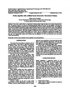
Fig. 4. Competitive state resulting from the collision of Separated Ethernet. deciding the Backoff slot time, compete in a shorter slot time. When a collision occurs on the improved BEB algorithm, the re-transmission time is decided by the number of collisions. If the fixed window size in a competitive situation is W, and r is the random slot time, the station’s re-transmission times i and j can be shown as Ti and Tj. If i station’s priority is higher than station j’s, the equation can be shown as (1). Ti = W ∗ ri < Tj = W ∗ rj
(1)
Window size W is fixed, it can be shown as in (2). ri < rj
(2)
In the proposed S Ethernet, the control network transmitting station’s random slot time value is rc, and the data network transmitting system’s is rd. The random slot time is decided by the number of retransmissions n, and is shown as (3) and (4). rc = random( ) rd = random( )
(3) (4)
Namely, the control network with a higher priority gets the lower competitive section. Fig. 4 shows the giving of priority, to the Backoff algorithm applied to the building network system. 2.3. Separated Ethernet frames All the frames transmitted on the channel for the integration of building networks must be classified into data network frame and control network frame. Fig. 5 shows the Separated Ethernet frame’s structure. It is a form of which, a 2 byte field called Network is added to the existing Ethernet. The contents of this field are shown in Table 2. The values of Network 1 and 2 are used to discriminate control network and data network. The control value is a designated value, which is used to
Table 2. Network Ethernet. Name Network 1 Network 2 Control
field values of the Separated Code 0x00 0x01 0x10
add the MAC algorithm, an algorithm that can form the most suitable network by establishing the Separated Ethernet’s constant value.
3. SIMULATION The proposed Separated Ethernet is verified using OPNET’s OPNET Modeler simulator. A LAN environment, which is consisted by 10 stations of 10MBps Link Models, is simulated under different scenarios of node model and created packet amount settings. To understand and valuate the performances of the Separated Ethernet, 4 scenarios have been made. Fig. 6 shows the simulating process of OPTNET simulator. One model from the existing Ethernet and three models of Separate Ethernet applied ones were used in the node model simulation. Separate Ethernet applied DDC(Direct Digital Controller) indicates the control facilities used in buildings, and the Separated Ethernet applied Client PCs indicates the data processing facilities. Web Server is the device that connects these two networks. In the results estimated in the simulation, the values are numbers of transmitted packets, and of collisions in each station, and the mean value of the End-to End Delay, which is the time during which packets of two networks are transmitted. 3.1. Confirming the Queue’s priority In the scenario of confirming the Queue’s priority, packets are generated from the upper two layers of the Web Server and is input to Queue, from a network environment consisted of five DDCs, four Client PCs
Separated Ethernet Frame Preamble 7 Byte
SFD 1 Byte
Destination Address 6 Byte
Source Address 6 Byte
Type 2 Byte
Network 2 Byte
Data 46 ~ 1500 Byte
Fig. 5. The structure of Separated Ethernet.
Description Control Network Data Network Ext - Ethernet
CRC 4 Byte
Fig. 6. Simulation environment.
Ethernet Algorithm for Building Network Integration Using TCP/IP
67
Fig. 7. Node models used in simulation.
Fig. 9. Results of scenario 2.
Fig. 8. Results of scenario 1. and one Web Server. The packets are generated every 5 seconds for 100Bytes, from both the control network packet and data network packet. This scenario’s result is shown in Fig. 8. The control network’s End-to-End Delay average is 0.103[ms], the data network’s End-to-End Delay average is 0.215[ms]. The control network’s packet has been transmitted twice faster than the data network packet. The two packets have a regular Delay value, which is because there were no collision on the LAN, due to the packet’s being generated from a single station. 3.2. Confirming the Backoff Priority In the scenario of confirming the Backoff’s priority, each packet is generated every second for 1024 Bytes, from the stations of control facilities and data facilities of a LAN environment of DDC and five Client PCs. The End-to-End Delay average is shown on Fig. 9. These results confirm that the control network’s transmission time is always shorter than that of the data network, as the control network’s Delay value is 1.602[ms] and the data network’s Delay value is 3.595[ms]. 3.3. Separated Ethernet’s performances under overload To study the performances of the Separated Ethernet under a sudden, big amount of traffic on the
data network, five control facilities and 5 data facilities are connected to one bus. The control facility station generates 100 byte packets every 0.1[sec], and beginning at 600 seconds all the stations of the data networks generate 1024 byte packets every 0.1[ms]. The End-to-End Delay average is shown in Fig. 10, and the amount of packet loss is shown on Fig. 11. As shown in Fig. 10, the control network’s delay increases as the data network’s packets become generated. But the results show a big distinction of 36.7[ms] and 236[sec]. Also, the data network’s packet loss remains but the control network does not have any packet losses.
Fig. 10. Results from scenario 3’s transfer delay2.
Fig. 11. Packet loss from scenario 3.
68
Kyung-Bae Chang, Il-Joo Shim, and Gwi-Tae Park
3.4. Comparison between Ethernet and Separated Ethernet To compare the performances of the existing Ethernet and Separated Ethernet, the same amount of data has been generated for the same amount of intervals from the two LANs, each composed of Ethernet and Separated Ethernet, and the End-to-End Delay of the two LANs have been measured. Two kinds of simulations were conducted, one where all the stations generate packets of a low, 1024Byte data every second, and one where packets of 1024Byte data are generated every 6 seconds. Fig. 12 shows the results of scenario 4 under low traffic. The existing Ethernet’s transmission delay is smaller than the proposed S-Ethernet, but its differences are much smaller than the total transmission delay. Fig. 13 shows the results of scenario 4 under high
Fig. 12. Results of scenario 4 under low traffic.
traffic. As the traffic increases, the transmitting delay of the two Ethernet methods become bigger, but this difference is too small comparing to the total transmission delay. In other words, there is little difference in the performances of the existing Ethernet and the Separated Ethernet. By these results, we could confirm that the control network’s packets have a fast and stable transmitting speed, even when a lot of packets are generated from the data network by the priority given to the Queue and Backoff algorithm. Also, there were little differences with the performances of the existing Ethernet.
4. CONCLUSION & FUTURE WORKS This paper proposed the integration of the building’s control network and data network. We detected some problems that occur with the integration of the two networks, like transmitting delay, packet loss and security matter. We proposed the Separated Ethernet to solve these problems. Ethernet MAC Protocol, which is in charge of layer1 and layer2 of the OSI 7 layer has been logically divided with the network, and the control network system has been prioritized on the Separated Ethernet. The Separated Ethernet has been designed by adding Backoff Priority, double Queue and Queue priority functions to the existing Ethernet. The designed Separated Ethernet’s logical dividing and priority giving functions have been verified by OPNET Modeler, by separate scenarios. [1] [2] [3]
[4]
[5]
[6]
[7] Fig. 13. Results of scenario 4 under high traffic.
REFERENCES http://www.echelon.com/ http://www.bacnet.org/ F. L. Lian, J. R. Moyne, and D. M. Tibury, “Performance evaluation of control networks,” IEEE Control System Magazine, vol. 21, no. 1, pp. 66-83, 2001. G. C. Lee, T. J. Kim and S. Lee, “Performance evaluation of switched ethernet for real time industrial communication,” Journal of Control. Automation and Systems Engineering (in Korean), vol. 9, no. 1, pp. 90-98, 2003. N. Krommenacker, T. Divoux, and E. Rondeau, “Using genetic algorithms to design switched ethernet industrial networks,” Proc. of the IEEE International Symposium on Industrial Electronics, vol. 1, pp. 152-157, 2002. IBS Korea, Environment Friendship Type Smart Building Technical Development Research Paper, Construction Technology Research and Development Business Research Paper, 2003. C. S. Leem, “Performance evaluation of building network system integration using TCP/IP,” Master’s thesis, Dept. of Electrical Engineering,
Ethernet Algorithm for Building Network Integration Using TCP/IP
Korea University, 2004. K. H. Lee, J. S. Shon, and W. T. Hwang, Construction-Information-Equipment System of Intelligent Building, Kimoondang, 2002. [9] IBS Korea, Entrance and Application of Intelligent Building System, Kitari Book Company, 2002. [10] W. S. Song, S. H. Hong and S. T. Bushby, NISTIR 7038: A Simulation Analysis of BACnet Local Area Networks, National Institute of Standards and Technology, 2003. [11] W. Zhang, M. S. Branicky, and S. M. Philips, “Stability of networked control system,” IEEE Control System Magazine, vol. 21, pp. 84-99, 2001. [12] Y. Xiao, “Backoff-based priority schemes for IEEE 802.11,” Proc. of the International Conference of Communications, vol. 3, pp. 1568-1572, 2003. [8]
Kyung-Bae Chang received the B.S. degree in Electrical Engineering from Hong-Ik University, Korea, and the M.S. degree in Mechatronics Engineering from GIST (Gwang-Ju Institute of Science and Technology), Korea. He is currently a Ph.D. candidate in the Electrical Engineering, Korea University. He was with Hyundai Autonet, Korea, from 1997. His research interests include Safety Electronics System, Testing, Quality Assurance, Reliability Modeling and Analysis, Intelligent Building System, Embedded System and Ubiquitous Computing. Il-Joo Shim received the B.S. and M.S. degrees in Electrical Engineering from Korea University at Seoul, in 1987 and 1989, respectively. From 1989 to 1999, he was a Senior Engineer at LG Industrial Systems, where his activities included the design and development of distribution automa-tion system (DAS). Since 1999, he is a Ph.D. candidate in the School of Electrical Engineering at Korea University. From 2001 to 2002, he is a Research Professor in the School of Information & Communication Engineering at Daeduk College. Since 2003, he is a Research Professor in the School of Electrical Engineering at Suwon University. His research interests include webbased remote control, power quality monitor, digital protective relay, intelligent building system (IBS), contextaware and Ubiquitous computing systems. He is a member of KIEE, ICASE and IEEE.
69
Gwi-Tae Park received the B.S., M.S. and Ph.D. degrees in Electrical Engineering from Korea University in 1975, 1977 and 1981, respectively. He was a Technical Staff Member in the Korea Nuclear Power Laboratory and an Electrical Engineering Faculty Member at Kwangwoon University, in 1975 and 1978, respectively. He joined Korea University in 1981 where he is currently a Professor in Electrical Engineering. He was a Visiting Professor at the University of Illinois, UC and the University of Maryland, in 1984 and 1996, respectively. Dr. Park is presently serving as the President of the Intelligent Building System (IBS)-Korea. His research interests include soft computing technique and its application to semiconductor processes, adaptive signal processing, computer & control networks and their applications to robots, home automation, security systems, smart car, and IBS. He was a recipient of KIEE Paper Award and Academic Achievement Award. He is a member of KIEE, ICASE, and KFIS.