This tag is used for both VLAN operation and. QoS priority identification. The first 2 bytes (TPI) of the tag is used to identify an 802.1Q frame (all 802.1Q.
Ethernet QoS Modeling in Emerging Scenarios M. Carmo, J. Sá Silva, E. Monteiro, P. Simões and F. Boavida University of Coimbra, Laboratory of Communications and Telematics DEI / CISUC Polo II, 3030 Coimbra, PORTUGAL Tel.: +351 239 790000 Fax: +351 239 701266 {maxweel, sasilva, edmundo, psimoes, boavida}@dei.uc.pt
Abstract The lack of Quality-of-Service (QoS) in MAC layer of Ethernet networks was overcome with the advent of the IEEE 802.1Q and IEEE 802.1p standards. This paper describes the development of new modules to the NS-2 simulator that makes possible the simulation of QoS over Ethernet networks. The modules are related to the IEEE 802.1Q and IEEE 802.1p standards and implement the recommendations concerned to traffic prioritization. The modules are intended to run in a full-duplex switched LAN network and are part of the contribution of the Laboratory of Communications of the University of Coimbra (UoC) to EuQoS project [1].
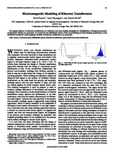
operation and administration of different topologies. The standard adds an extra 4 bytes tag in the MAC header (Figure 1). This tag is used for both VLAN operation and QoS priority identification. The first 2 bytes (TPI) of the tag is used to identify an 802.1Q frame (all 802.1Q frames have this field set to 0x8100). The next two bytes consist of 3 fields: a canonical format indicator (CFI), a VLAN field, and a 3 bits length field used to differentiate the priority of packets. .
1. Introduction The Network Simulator NS-2 [2] is a discrete event simulation tool widely used in network research. It is an open source tool that allows the simulation of a huge variety of network protocols, ranging from application protocols, like FTP and HTTP, to network access technologies such as Ethernet. Written in C++ and Object-Oriented Tcl (OTcl), NS-2 is quite flexible and allows new modules to be added. Its extensibility is explored by several researchers and new modules are constantly being developed. NS-2 also offers several ways to process data output. Results of a simulation can be analyzed with tools like NAM (Network Animator), Xgraph[3] and gnuplot[4]. The development of 1 Gbps and 10 Gbps Ethernet has allowed the use of Ethernet technologies in a variety of scenarios, ranging from Small Office Home Office (SOHO) environments to Wide Area Networks (WANs). In this context, there is an increasing demand for QoS support on Ethernet networks. The IEEE 802.1p and 802.1Q [5] specifications deal with these requirements, bringing traffic prioritization capabilities to the MAC layer. The IEEE 802.1Q standard supports the operation of virtual LAN (VLAN) bridges that permit the definition,
Figure 1. IEEE 802.1Q frame Although IEEE 802.1Q defines a priority field, it does not describe their possible values and functional details. This is performed by the IEEE 802.1p standard, which is part of the IEEE 802.1D [6]. The IEEE 802.1p standard supports the provisioning of expedited traffic in a LAN network. It defines up to eight classes of traffic (see Section 3.1) to allow differentiated treatment to frames. To accomplish this, the 3-bit priority field defined by 802.1Q is used. In this way, Ethernet can, for instance, prioritize video or audio frames. The IEEE 802.1p can also be defined as best-effort QoS at Layer 2, since the traffic is simply classified and sent to the destination; no resources reservations are established. The IEEE 802.1p standard is also concerned with provisioning of dynamic multicast filtering, but this subject is not taken into account in this paper. The rest of the paper is organized as follows. The next section discusses the main characteristics of Ethernet technology and briefly presents the EuQoS Project. Section 3 describes the implementation details of the modules related to 802.1p and 802.1Q. Related OTcl
interfaces and integration with NS-2 are also discussed in this Section. Section 4 presents some evaluation examples that illustrate the use of the developed modules. At last, conclusions and future work are presented in Section 5.
2. Emerging Ethernet Scenarios 2.1. Ethernet Technology The Ethernet designation refers to the family of local-area network (LAN) protocols covered by the IEEE 802.3 working group. The original IEEE 802.3 draft standard was approved by the 802.3 working group in 1983 and was subsequently published as an official standard in 1985 (ANSI/IEEE Std. 802.3-1985). Since then, a number of supplements to the standard have been defined to take advantage of improvements in the technologies and to support additional network media and higher data rate capabilities, plus several new optional network access control features. The Ethernet family comprises a wide range of data rate capabilities (10 Mbps, 100 Mps, 1 Gbps and 10 Gbps), network media, network topologies and operation modes. Nevertheless, it is possible to establish a common denominator between Ethernet technologies with current relevance: today’s Ethernet is predominantly based on switched, full-duplex operation; based on star topologies; and designed for full-duplex twisted pair (cooper) cables and/or optical fiber cables.
2.2. Emerging Scenarios Historically, Ethernet has been a LAN technology. Ethernet dominates this market for decades, driven by two key factors: simplicity (backwards compatibility, very competitive prices, easiness of deployment) and the ability to satisfy the continuous demand for higher data rates. Today, with the possible exception of emerging WLAN solutions, there is no relevant competitor to the Ethernet technology for mainstream local area networks. However, Ethernet is not limited to the LAN market. It is also assuming an important role into Metropolitan Area Networks and even Wide Area Networks. Newer Ethernet technologies, supporting longer transmission distances (up to 150 km), along with the dissemination of optical fiber installations, result into the same factors that dictated the Ethernet success its native LAN environment: lower costs (installation, maintenance), simplicity and high data rates. This widespread dissemination is resulting in new – and heterogeneous – utilization scenarios for the Ethernet
technology, depending on geographic distribution, number and type of the users. It is possible to identify at least six distinct scenarios: - Small Office and Home Office (SOHO) scenarios, where Ethernet is used on a very small scale. Typically a SOHO Ethernet is limited to one office with few users connected to it. Cheap, lowend Ethernet equipment is used to connect the PC of the users, which enables the sharing of the resources (such as printers) and access to the Internet. - Large building scenarios. Large business buildings are usually equipped with Ethernet technology, which is leased by the business that is using the offices in the building. The large building Ethernet consists usually of one high-capacity fiber-optic backbone and many smaller stp/utp Ethernet segments bridged trough the backbone. Since many companies use the same Ethernet, the network is partitioned using virtual LAN (VLAN) to ensure the privacy of the data communication within each company. Large buildings themselves are either connected to a MAN or have a highspeed WAN connection (>= 155 Mbps), which is shared by all companies within the building. - Campus scenarios. Most modern university campuses are equipped with Ethernet networks. The campuses are usually dispersed over several interconnected buildings Due to the nature of university operation, a campus network consists of numerous and heterogeneous sub-networks, interconnected in a single huge campus network. - MAN organization scenario. In these scenarios, two Ethernet variants are applicable: 1Gb Ethernet and 10Gb Ethernet. There is a clear advantage of 10Gb Ethernet over 1Gb Ethernet, both in terms of bandwidth and range. 1Gb Ethernet solutions are also possible, but are limited in terms of distance between metropolitan sites. - Residential MAN Scenario. Ethernet Passive Optical Network (EPON) is a new emerging fiberoptic technology for connecting CO with the business and residential customers (the “last mile”). In contrast to point-to-point fiber-optic technology, an EPON uses a point-to-multipoint architecture (without active electronic components), which aggregates the connections of many customers to a single fiber at the CO. This enables the sharing of the cost of the expensive active electronics at CO by many customers.
3
-
Another advantage of EPON is the support for variable length frames of up to 1518 bytes. EPON networks consist of an OLT (optical line terminal) at the CO, split points and ONU (optical network units) located in the customer premises. WAN scenario. 10Gb Ethernet provides an adequate communications technology solution for wide area network scenarios. In fact, one of the objectives of the IEEE 802.3ae Task Force was to extend the scope of Ethernet to MANs and WANs, and this was fully achieved with the developed 10Gb Ethernet specifications.
2.3. EuQos Project EuQoS is an EU Integrated Project established to bring end to end QoS support for internet applications. EuQos targets a wide range of network technologies – including Ethernet – and applications, such as such applications include voice, video-conferencing, video-streaming, educational, tele-engineering and medical applications. As such, one the research lines of the EuQos Project consists on the development and application of modeling and simulation tools in order to assess and validate QoS mechanisms. The work presented in this paper was developed in the context of this line of work.
3. NS-2 modules for QoS in Ethernet networks Although NS-2 offers support to the simulation of Ethernet networks, it does not implement the 802.1Q and 802.1p standards. To make possible the simulation of QoS in Ethernet networks, we developed a new specific queue object – EthPrioQueue - that implements the recommendations of the IEEE 802.1p standard related to traffic prioritization. Basically, the queue presents the following properties: - It can be configured to use up to eight virtual queues to group incoming LAN packets into separate traffic classes according to IEEE 802.1p recommendations. - The forwarding mechanism is implemented in such a way that packets from a given virtual queue are selected to transmit only if a higher order virtual queue is empty at the time of selection. The implementation of the IEEE 802.1p here described is intended to run on a scenario of switched Ethernet networks with full-duplex connections. To make possible the classification of packets by the prioritization queue, it is necessary that the packets are
previously marked with a user priority value. To accomplish this task, a specific agent – PriAgent – was also developed. EthPrioQueue and PriAgent inherited several functionalities from other NS objects and their functions are described below.
3.1. EthPrioQueue EthPrioQueue is the major component in the developed modules, and it is used as any other queue, but on IEEE 802.1p simulations. Its function is to perform the prioritization of packets, giving preferential treatment to those identified as being of higher priority. This is supported by the user priority value of each packet which is associated with a specific traffic type. They are defined by IEEE 802.1p standard and assume one of the levels, shown in Table 1. Table 1. User priority values recommended by IEEE 802.1p standard IEEE 802.1p User Priority 7 (highest) 6 5 4 3 0 2 1 (lowest)
Traffic Type Network Management Voice Video Controlled Load Excellent Effort Best Effort Undefined Background
. EthPrioQueue supports up to eight virtual queues that are used to group incoming packets into separate traffic classes. Each packet is routed to a specific queue according to its user priority value. If a packet has a user priority value less than zero, it will be treated as a best effort packet (user priority equal to zero). If the priority value is greater than seven, the packet will be classified as a highest priority packet (as if it was set with user priority seven). Implementing exactly eight virtual queues is not mandatory, being possible any number from 1 to 8. In those cases, when the number of virtual queues is less than 8, packets with different user priority values can be mapped to a same queue. For example, on a configuration with only one virtual queue, all packets are mapped to this same queue. In this case, all packets are seen as in the same level without any preferential treatment.
IEEE 802.1p recommends a mapping of user priority values for the number of traffic classes (virtual queues) available. This mapping is implemented by EthPrioQueue and is shown in Table 2. For example, a switch with only two queues will set packets with a user priority of 0, 1, 2 or 3 into the lower priority queue and packets with a user priority of 4, 5, 6 or 7 into the higher priority queue. Packets with user priority 0 are given preferential treatment over user priority 1 and 2 in queues that implement four or more virtual queues. An explanation to these mappings is presented in Annex G of the IEEE 802.1D.
registered headers like TCP header, IP header and RTP header, even when a specific header is not used at all. The common header (the top header of the stack in the figure) is used internally by NS and it is presented in all packets. Currently, the PrioAgent is using the priority field of the IPv6 header to set the user priority of the packets. An alternative would be creating a new packet header and using it to set the priority values.
Table 2. Recommended user priority to virtual queue mapping
Figure 3. Format of a NS-2 packet
3.3. Interfaces OTcl
To retrieve packets from the queue and forward them downstream (to another NS component, which depends of the simulation scenario) it is necessary a scheduler mechanism. On the scheduler implemented by EthPrioQueue, packets from a certain queue are selected for transmission only if all virtual queues with higher order are empty. For example, if there are packets in queue 0 and 5, packets of queue 0 only will be forwarded when all packets from queue 5 has been already sent.
3.2. PrioAgent PrioAgent is a user-priority-aware agent responsible for generating packets and setting them with a specific user priority level. In the NS-2, packets are composed by a stack of headers and a (optional) data field (see Figure 3). When a simulation is initialized, each packet is configured with all
In an Otcl script, the new queue class is referenced as EthPrioQueue. The class inherits from generic Queue class, as other specialized queue classes do. On NS-2, a link is an object used to connect nodes and includes other components, like the queue class (Figure 4).
Figure 4. Link component implemented by NS-2 Inside the link, the queue is directly connected with Delay and Agent/Null objects. Packets removed from a queue are passed to the delay object that is responsible for simulate the link delay, and packets dropped are sent to a null agent where they are discard. A link is created as an object connecting two nodes. This is made through the simplex-link or duplex-link procedures. They receive as parameters the two nodes to
5
be connected, the link bandwidth, delay and the queue type. The following line shows the creation of a link between nodes n1 and n2 with 10Mbps of bandwidth, 3ms of delay, and using the EthPrioQueue. $ns is the simulator object, $n1 and $n2 are nodes objects. $ns duplex-link $n1 $n2 10Mb 3ms EthPrioQueue The class presents the setNumQueue method, which can be called by OTcl scripts, and it is used to set the number of virtual queues (other methods related with the inherited class Queue can, obviously, be used). This method is invoked once, after the creation of the link. By default, EthPrioQueue uses eight virtual queues. The statement below presents a queue configured with five virtual queues. The first and second lines get a reference to the queue used on the link between nodes $n1 and $n2.
scenario deals with the category of business which support from 1 to 10 workers. Figure 5 illustrates the network topology used in all the scenarios. The nodes n0, n1, n2 and n4 represent terminal equipment (computer, printers, etc.). The intermediate node can represent a switch that connects the nodes n0, n1 and n2 to n4. VoIP traffic was generated between nodes n0 and n4. During the VoIP communication, traffic between n1-n4 and n2-n4 is also generated in order to have packets congestion in the queue n3-n4. These traffic patterns are generated by traffic sources components located at nodes n1 and n2.
set ln [$ns get-link $n1 $n2] set pq [$ln queue] $pq setNumQueue 5 A PrioAgent OTcl object can be created by calling the Agent/prioAgent class. For example, the following statement instantiates a prioAgent: set pagent [new Agent/prioAgent] The class offers the method userPriority_ which can be used to configure the priority value of the packets generated by the agent. The method accepts one parameter, an integer number in the range from zero to seven, which represents the priority value. Packets generated after this call are set with the specified priority value until userPriority_ is called again with a new parameter. By default, the user priority value is zero. The EthPrioQueue and the PrioAgent were both implemented as C++ classes. They were developed for version 2.27 of the NS-2 and tested on top of Linux operating system.
4. Evaluation examples 4.1. Scenarios In order to evaluate our implementation we built five scenarios based on a SOHO environment. A SOHO
Figure 5. A SOHO scenario
4.2. Workload Modelling We considered two basic types of workload: packets that were sent as best-effort traffic and delay-sensitive packets that were sent as high-priority traffic. To represent the high-priority traffic we used a G.711 [7] VoIP model. High-quality voice traffic imposes several requirements on the network, like a low one-way delay, to maintain the quality of the communication. The G.711 coded is described as having a raw bandwidth of 64 kbps, a 20ms of inter arrival delay, and a constant frame size. Generally, VoIP applications use Voice Activity Detection (VAD) mechanisms to avoid the sending of packets during periods of no voice activity. Although there are models describing this type of pattern [8], in our simulation studies it was not represented. Instead, to generate all the necessary VoIP traffic we used the CBR component. In each scenario, the CBR parameters were configured so that it was possible to emulate G.711 traffic without VAD support.
To represent periods of congestion, two different traffic sources were implemented: a CBR component that generated packets in a constant bit rate and an application that simulated MPEG-4 video streaming. To perform this last, we used some file traces [9] of long MPEG-4 movies. All the traffic sources (including VoIP and MPGE-4) were attached on top of prioAgent agents which were responsible for creating the packets and setting them with a specified user priority. The bit rate of the CBR component was chosen in a manner that it was possible to have enough congestion on the queues to analyze the packet delays along the time. In all the scenarios, we traced the traffic flows and calculated the one-way packet delay (the difference between the received and transmitted time).
4.3. Using Drop Tail Queue and CBR In this scenario we used a DropTail queue in the link n3n4 (Figure 5), and two CBR components connected to nodes n1 and n2. The one-way delay experienced by each of the traffic flows are presented in (Figure 6). Initially, the VoIP traffic delay was near to 20ms. At the first second, the node n1 started to transmit, increasing traffic congestion in the queue. Consequently, there was a rise in the delay experienced by all the flows. After 3.0 seconds, node n0 stopped transmitting packets (Traf0 in the chart legend). This reduced the number of packets in the queue and, consequently, the delay.
To a highly-sensitive delay application like VoIP, this is far from suitable.
4.4. Using EthPrioQueue Queue and CBR In order to give a preferential treatment to traffic VoIP, in this scenario we replaced the DropTail queue with an EthPrioQueue component configured with 8 virtual queues (default). To allow queue to prioritize VoIP traffic we set all of its packets with user priority 6. Traffic between n1-n4 (Traf0 in the chart legend) and n2-n4 (Traf1) were set with values 0 (best-effort traffic). In this way, VoIP traffic had the higher priority and would be forwarded first during the congestion periods. The delay of the VoIP traffic along the time is shown on Figure 7. Before 1.0 second of simulation the delay was around 20ms. After that, node 1 (Traf0) started transmitting, rising the congestion in the queue. During the queue congestion, Traf0 and Traf1 experienced a steady increase in the delay while the VoIP traffic suffers from a litter variation. After 3.0 seconds Traf0 stopped, decreasing the queue congestion.
Figure 7. Packet delay in a EthPrioQueue queue
4.5. Using Drop Tail Queue and Video Streaming Traffic
Figure 6. Packet delay in a DropTail queue As there is no differential treatment on a DropTail queue, all the traffic flows suffer from the same delay problems.
In this scenario, we replaced the CBR components in the nodes n1 and n2 with MPEG-4 video traffic sources. Figure 8 presents the one-way delay of the three traffic flows during 45s, approximately. As there is no traffic prioritization, the VoIP packets vary according to the queue availability, reaching a peak value near to 17ms.
7
4.7. Using EthPrioQueue Queue and Video Streaming Traffic with different Priority Values In this last scenario, all the traffic flows were treated with different priorities. The VoIP traffic was associated with the highest-priority, followed by the Video1 and Video2.
Figure 8. VoIP and Video traffic using a DropTail Queue
4.6. Using EthPrioQueue Queue and Video Streaming Traffic This scenario used an EthPrioQueue to classify the above traffic in two classes: VoIP traffic and Video traffic. Once VoIP packets are more delay sensitive, they were set with the higher-priority by the agent responsible for generating them. In this way, the VoIP traffic had precedence in periods of congestion. In the Figure 9 it is possible to distinguish the two classes. The first is composed by the video1 and video2 traffic flows and has an increased delay, compared to the second (the VoiP traffic).
Figure 10: Different priority levels Compared with the previous scenario, the traffic of the Video1 has a more smooth behaviour. On the other hand, the traffic represented by Video2 (the lowest priority) faced considerable increase of delay. The peak during the interval between 10s and 20s is due to a high number of packets of the two other flows that are coming to the queue. As they have higher priority they are forwarded first, causing the long delay. In a common switch that does not perform packets differentiation, all the traffic has the same treatment and share common problems like long delay. In the first scenario, for example, the VoIP traffic started with a delay around 20ms and experienced a peak delay over 150ms, during the congestion period. On the other hand, the use of the EthPrioQueue component (second scenario) kept the high-priority traffic with a low delay during all simulation. However, all the low-priority traffic had their delay increased due to an augment of the time they had to wait on the queue.
4. Conclusions Figure 9. Two classes of traffic: VoIP and Video
Ethernet technologies have been widely adopted in different environments. The advent of 1Gigabit and 10 Gigabit Ethernet, and the adoption of full duplex switched topologies have increased the need of QoS support by
Ethernet networks. The IEEE 802.1p and 802.1Q standards bring QoS to Ethernet allowing preferential treatment of traffic in MAC layer. This paper presented an implementation of the IEEE 802.1Q and 802.1p for NS-2. Through the evaluation examples it was possible to analyze how the prioritization of the traffic can affect the performance of the overall network. The proposed modules can be useful in several studies. For example, they can allow the network administrator to evaluate and compare different priority values for the applications, in order to choose the more suitable ones. Also, using the appropriate traffic models, it is possible, for example, to analyse how many VoIP applications the network can support. The agent developed to set the packets with user priority can be attached to an application-level data source and can be used in several environments, as those described in the evaluation examples. When this agent is not suitable (e.g. in scenarios where a transport protocol like TCP has to be simulated), a piece of code that mark packets with a user priority has to be developed. This is inconvenient and we are planning, as a future work, some architectural changes in our modules to overcome this problem. As a future work, we also plan to extend our evaluation work to different Ethernet networks, like EPONs.
Acknowledgements This work was partially funded by the European Union 6th Framework Programme under contract IST FP6 IP 004503 EuQoS Integrated Project. The authors also acknowledge the various comments and valuable suggestions received from the EuQoS project team,
References [1] EuQoS – End-to-end Quality of Service Support for Heterogeneous Network, www.euqos.org. [2] The Network Simulator, http://www.isi.edu/nsnam/ns. [3] Xgraph, http://www.isi.edu/nsnam/xgraph. [4] gnuplot homepage, http://gnuplot.sourceforge.net, 2004. [5] 802.1Q, Standards for Local and metropolitan area networks, “Virtual Bridged Local Area Networks”, IEEE Computer Society, 2003. [6] 802.1D, Standards for Local and metropolitan area networks, “Media Access Control (MAC) Bridges”, IEEE Computer Society, 2004. [7] Recommendation G.711, “Pulse Code Modulation (PCM) of Voice Frequencies,” ITU, Nov. 1988. [8] Chen-Nee Chuah, “A Scalable Framework for IP-Network Resource Provisioning through Aggregation and Hierarchical Control”, Ph.D. Dissertation, 2001, www.ece.ucdavis.edu/~chuah/thesis/thesis_summary.html. [9] Frank H.P. Fitzek and Martin Reisslein, “MPEG4 and H.263 Video Traces for Network Performance evaluation”, volume 15 no. 6, pages 40-54. IEEE Network, November/December 2001.