Proceedings of the 38th European Microwave Conference
Microstrip Switchable Bandstop Filter using PIN Diodes with Precise Frequency and Bandwidth Control Zabdiel Brito-Brito#, Ignacio Llamas-Garro#1, Lluis Pradell-Cara#, Alonso Corona-Chavez* #
Signal Theory and Communications department, Technical University of Catalonia Campus Nord UPC, Jordi Girona 1-3, D3 building, CP 08034 Barcelona, Spain 1
[email protected]
*
Large Millimeter Telescope, National Institute for Astrophysics, Optics and Electronics Luis Enrique Erro 1, Tonantz., CP 72000 Puebla, Mexico
Abstract— In this paper a switchable bandstop filter able to switch between two different central frequency states while precisely maintaining a fixed bandwidth is presented. The filter topology allows precise control over the design parameters frequency and bandwidth, achieved by choosing adequate resonator sections which are switched by PIN diodes to obtain two discreet states. The central frequency control was obtained by modifying resonator length. Bandwidth control was achieved by choosing a resonator width and controlling the normalized reactance slope parameter of a decoupling resonator by means of a switchable resonator extension. The filter was designed to have center frequencies of 2 and 1.5 GHz both having an 8% fractional bandwidth. The comparison between simulations and measurements showed a central frequency deviation of 4 MHz for the 2 GHz frequency response, and a deviation of 2 MHz for the 1.5 GHz frequency response. The fractional bandwidth deviation for the 2 GHz filter response was 0.67%, while at 1.5 GHz a 0.4% deviation was observed. The simulation and measured responses are in very good agreement.
I. INTRODUCTION Switchable filters can reduce the complexity of a system by allowing filter re-configurability instead of having switched filter banks; most designs found through literature focus on central frequency control, however for the different central frequency states, the bandwidth is not included as a design parameter. The filter described in this paper, is capable of having two central frequency states, where precise bandwidth control is used to fix filter central frequency states to an 8% fractional bandwidth. In [1],[2] tunable bandstop filters using varactor loaded resonators are presented. The filters are capable of tuning their center frequency; however the stopband bandwidths of the filters increase rapidly for different filter central frequency states. The microstrip bandstop filter discussed in [3] uses a tuning plate with a trilayer thermal actuator to achieve re-configurability; the filter has frequency operation range from 6.09 to 5.75 GHz, without filter bandwidth control. In [4] a tunable bandstop filter was designed using electromagnetic band gap structures on CPW transmission lines, MEMS bridges were used as tuning elements, a variable central frequency from 17 to 22.5 GHz
978-2-87487-006-4 © 2008 EuMA
was obtained, the bandwidth progressively changes with filter center frequency. The bandstop filter in [5] uses RF MEMS switches, the filter is based on microstrip transmission lines with radial stubs, presenting a tuning rage form 8 to 15 GHz, however the bandwidth has arbitrary values at each center frequency. In [6] a bandstop filter based on quarter wavelength stubs is discussed, the filter is based on cantilever MEMS switches, central frequencies with different bandwidths were obtained from 39 to 58 GHz. In [7],[8] PIN diodes have been used to control filter central frequency, and varactors provide a continuously tuned bandwidth at a given filter central frequency. The filter has a frequency range from 0.5 to 2 GHz with bandwidths in the range of 30 to 42%. The microstrip filter presented in this paper consists of a main microstrip transmission line, and two switchable decoupling half-wavelength resonators. Center frequency is controlled by adjusting the length of the switchable resonators; on the other hand, a section of transmission line on the resonators allows the adjustment of the normalized reactance slope parameter of the resonator to the main transmission line [9], to control the fractional bandwidth at each center frequency. The objective of this filter was to produce central frequencies of 1.5 and 2 GHz, both having a same fractional bandwidth of 8%, this was achieved using the proposed switchable filter topology. It can be noted that design parameters can be used to produce different bandwidths and center frequencies using the topology discussed in this paper. This paper is divided in four sections, section II contains a discussion of the proposed filter topology, describing how the filter design parameters frequency and bandwidth were controlled. Section III contains a discussion of the simulated and measured filter responses and bias circuitry. Finally section IV gives an overall conclusion of this work. II. SWITCHABLE BANDSTOP FILTER TOPOLOGY The design of a narrow bandstop filter can be based on the normalized reactance slope parameter of individual resonators as discussed in [9]. Taking the filter terminating impedance
1707
October 2008, Amsterdam, The Netherlands
xi g0 = Z0 g1ΩC FBW
(1)
Where the g values correspond to the lowpass Chebyshev prototype filter, ΩC is the angular cutoff frequency, FBW is the fractional bandwidth for the filter, and xi/Z0 is the normalized reactance slope parameter of an individual resonator coupled to the main transmission line. The lowpass prototype g values used for the two resonator filter are summarized in table I for a 0.1 dB passband ripple.
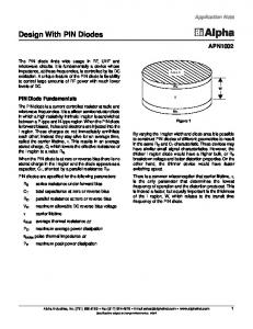
paper, a minimum achievable spacing between the main line and resonator with good resolution was defined as a 100 µm gap. From Fig. 2 we demonstrate that xi/Z0 can also be adjusted by varying resonator width, this parameter was used to fix xi/Z0 for the 8% fractional bandwidth, allowing the filter to be realizable using standard photolithographic techniques, while maintaining adequate unloaded quality factor values for the resonators. 25
x / Zo
equal to the characteristic impedance of the immittance inverters results in the following equation:
TABLE I LOW PASS ELEMENT VALUES FOR THE CHEBYSHEV PROTOTYPE FILTER
g0 1.0
g1 0.8431
g2 0.6220
20 15
g3 1.3554
The plot of eq. (1) is shown on Fig. 1 using the filter design parameters, where an appropriate value of xi/Z0 can be obtained to achieve the 8% fractional bandwidth. To obtain xi/Z0 using a simulator [10], a single resonator coupled to the main line must be simulated as discussed in [9], and then an appropriate value of xi/Z0 can be determined by finding the appropriate spacing between the resonator and the main line using the following expression:
xi f0 = Z 0 2∆f 3dB
W1= 3,38mm W2= 2,48mm W3= 1,08mm
(2)
10 100
200 Spacing (µm)
300
Fig. 2 Resonator spacing from the main transmission line vs normalized reactance slope parameter for different resonator widths
Fig. 3 shows the two pole switchable bandstop filter topology using four PIN diodes. In this filter topology all PIN diodes are reverse biased to produce a filter central frequency of 2 GHz, and all PIN diodes when forward biased produce the 1.5 GHz central frequency. Resonator 1.5GHz
Resonator 2GHz
Where fo is the resonator center frequency and ∆f3dB is the 3dB bandwidth produced by the decoupling resonator. 24
λg2/2
22
Sp a
20
ci n g
D1
D2
λg1/2
D3
D4
x /Zo
Input
18
Output
16
λg1/4 λg2/4
14
Fig. 3 Two-pole Switchable bandstop filter
12 5
6
7 FBW (%)
8
9
Fig. 1 Fractional bandwidth vs normalized reactance slope parameter of a single resonator coupled to the main line.
It is apparent from Fig. 1 that larger fractional bandwidths require smaller xi/Z0 values, which results on small distances between the main line and the resonators. Depending on photolithographic resolution, this dimension can become critical for a given case, e.g. for the filter discussed in this
W
The relation between the normalized reactance slope parameter and the spacing between the main transmission line and both resonators is shown in Fig. 4. The length of the switchable resonator extensions in Fig. 3 are chosen to produce two central frequency states with a fixed fractional bandwidth. By altering these resonator extensions, other values of bandwidth and central frequency can be obtained. It is evident from Fig. 4 that for the two filter states, the value of xi/Z0 at both frequencies is approximately the same, thus a fixed fractional bandwidth will be obtained for both filter central frequency states.
1708
20 2GHz Resonator 1,5GHz Resonator
x / Zo
18 16 14 12 10 100
200 300 Spacing (µm)
400
diodes used in simulations, for both forward and reverse bias states are similar to the ones exposed in [12]. The forward “on” state of the diode was equivalent to a 3 Ω contact resistance of the anode and cathode, in series with a 6 pF junction and diffusion capacitance across the PIN diode’s depletion region. The reverse “off” state of the PIN diode was modeled as a 45 fF capacitance of the intrinsic region. Full wave simulations of the filter topology were made including lumped element models for the PIN diodes. The filter was optimized using [10] to accomplish the two discrete central frequencies. The measurements were taken using a HP8510C network analyzer. Table II contains a comparison between simulated and measured results, where a good agreement in terms of central frequency and bandwidth was obtained.
Fig. 4 Normalized reactance slope parameter vs resonator spacing from the main transmission line.
III. SIMULATED AND E XPERIMENTAL RESULTS Using the technique describe above, a bandstop filter was designed with central frequencies of 1.5 and 2 GHz. The fractional bandwidth of the design is fixed to 8%. A photograph of the fabricated filter is shown in Fig. 5.
TABLE II SIMULATED AND MEASURED RESULTS
Simulated Measured
f1 1.542GHz 1.540GHz
FBW1 8.5% 8.1%
f2 2.004GHz 2.000GHz
FBW2 8.08% 8.75%
A comparison between the simulated and measured responses of the switchable bandstop filter in the “off” state (with the four diodes in reverse polarization), is shown in Figs. 6 and 7. Fig. 6 contains S21 where a central frequency deviation of 4 MHz between simulations and experiment was found. 0
S21 (dB)
-5 Simulated Measured
-10 -15 -20 -25
Limiting RF Choke RF Input Main Line Resistor Resonator
PIN Diode
DC Port
-30 1,0
1,5
2,0
2,5
3,0
Frequency (GHz)
Fig. 5 Photograph of the switchable bandstop filter
A 1.524 mm thick Rogers substrate having a 30µm cooper metallization was used for the design. The substrate has a dielectric constant of 3.55, and a loss tangent of 0.0021. The diodes were HPND-4028 Avago Technologies beam lead PIN diodes. The layout including the DC bias lines was fabricated using standard photolithographic techniques. The Bias network consisted of a choke inductor to supply DC bias to the microwave circuit [11]. The inductor has a self-resonance at 1.7 GHz and provides isolation better than 20 dB at the frequencies of interest. Due to the high isolation of the choke inductor, the microwave is not influenced by the termination on port DC shown on Fig. 5. The current on each diode was limited to 10 mA by placing a 1 kΩ series resistance in the forward bias state, a voltage of -10 V was supplied in the reverse bias state. The lumped element models for the PIN
Fig. 6 Simulated and measured S21 (off state)
The difference between the simulated and measured fractional bandwidth was 0.67%. Fig. 7 contains S11 for the filter “off” state. Good agreement between the simulation and experiment was obtained. The measured and simulated results in the “on” state (with the four diodes in forward polarization) are shown in Figs. 8 and 9, Fig. 8 contains S21 where a central frequency deviation of 2 MHz between simulations and experiment was found. The difference between the simulated and measured fractional bandwidth was 0.4%. Fig 9 contains S11, for the filter “on” state. Good agreement between the simulation and experiment was obtained.
1709
S11 (dB)
0 -5 -10 -15 -20 -25 -30 -35
obtained by controlling the normalized reactance slope parameter of the resonators by means of a switchable resonator extension and defining resonator width. A very good agreement between simulations and measurements has been obtained. The filter topology also presents the possibility of producing other frequencies and bandwidths which can be controlled independently by choosing adequate resonator dimensions.
Simulated Measured
1,0
1,5
2,0
2,5
3,0
Frequency (GHz) Fig. 7 Simulated and measured S11 (off state)
0
ACKNOWLEDGMENT The authors would like to thank Marco Antonio LlamasMorote for assisting the measurements. This work has been financially supported by projects TEC2007-65705/TCM from Ministerio de Educación y Cultura and 2006ITT-10005 (AGAUR-Generalitat de Catalunya) REFERENCES
S21 (dB)
-5 [1]
Simulated Measured
-10
[2]
-15 [3]
-20 1,0
1,5
2,0
2,5
3,0
[4]
Frequency (GHz) Fig. 8 Simulated and measured S21 (on state)
[5]
0 [6]
S11 (dB)
-5 Simulated Measured
-10 -15
[7]
-20 -25
[8]
-30 1,0
1,5
2,0
2,5
3,0
Frequency (GHz)
[9] [10] [11]
Fig. 9 Simulated and measured S11 (on state)
IV. CONCLUSIONS A switchable bandstop filter with two discrete central frequencies having the same fractional bandwidth has been demonstrated. Bandwidth control for the filter has been
[12]
1710
Hunter, I.C.; Rhodes, J.D.; “Electronically Tunable Microwave Bandstop Filters” Microwave Theory and Techniques, IEEE Transactions on, Volume 30, Issue 9, p. 1361 – 1367, Sept. 1982. Chandler, S.R; Hunter, I.C; Gardiner, J.G.; “Active varactor tunable microwave filters” in European Microwave Conference, 1993. 23rd, Oct. 1993, p. 244 – 245 Yan, W. D.; Mansour, R. R.; “Compact Tunable Bandstop Filter Integrated with Large Deflected Actuators” in Microwave Symposium, 2007. IEEE/MTT-S International, 3-8 June 2007, p. 1611 – 1614 Karim, M.F.; Liu, A.Q.; Yu, A.B.; Alphones, A.; ”MEMS-based tunable bandstop filter using electromagnetic bandgap (EBG) structures” in . Asia-Pacific Microwave Conference Proceedings, APMC 2005, Volume 3, 4-7 Dec. 2005, 4 pp. Guizhen Zheng, John Papapolymerou, “Monolithic reconfigurable bandstop filter using RF MEMS switches” International Journal of RF and Microwave Computer-Aided Engineering, Volume 14, Issue 4, p. 373 – 382, July 2004. Takacs, A.; Neculoiu, D.; Vasilache, D.; Muller, A.; Pons, P.; Aubert, H.; Plana, R.; “Tunable MEMS Filters for Millimeter Wave Applications”, in International Semiconductor Conference 2006, Volume 1, Sept. 2006, p. 115 – 118 B.E. Carey-Smith; P.A. Warr; “Broadband-configurable bandstop-filter design employing a composite tuning mechanism” Microwaves, Antennas & Propagation, IET, Volume 1, Issue 2, p. 420 – 426, April 2007 Carey-Smith, B.; Warr, P.A.; “Broadband configurable bandstop filter with composite tuning mechanism” Electronics Letters, Volume 40, Issue 25, p. 1587 – 1589, 9 Dec. 2004 Jia-Sheng Hong and M. J. Lancaster, Microstrip Filters for RF/Microwave Applications, John Wiley & Sons, Inc. New York 2001. ADS Momentum (2006), http://eesof.tm.agilent.com/ Hongxi Xue; Kenington, P.B.; Beach, M.A.; ”A high performance ultra-broadband RF choke for microwave applications” in Evolving Technologies for Small Earth Station Hardware, IEE Colloquium on, 20 Feb. 1995, p. 1 – 4 Christopher T. Rodenbeck, James M. Carroll, Robert A. Flynt, Kai Chang; “Bias-dependent small-signal monolithic PIN diode modeling”, International Journal of RF and Microwave Computer-Aided Engineering, Volume 11, Issue 6 , p. 396 – 403, 24 Oct. 2001