with user-defined functionality can be easily included. MOVE framework is a ... plate for a given instruction is not available, a template spe- cifying a superset of ...
EVALUATING TEMPLATE-BASED INSTRUCTION COMPRESSION ON TRANSPORT TRIGGERED ARCHITECTURES Jari Heikkinen1 , Tommi Rantanen1 , Andrea Cilio1 , Jarmo Takala1 and Henk Corporaal2 1
Tampere University of Technology P.O. Box. 553, 33101 Tampere Finland ABSTRACT
In embedded systems, memory is one of the most expensive resources. Due to this, program code size has turned out to be one of the most critical design constraints. Code compression is one of the approaches to reduce the program code size; it results in smaller memories and reduced cost of the chip. Furthermore, code compression can decrease the power consumption of the chip. In this paper, a code compression method based on instruction templates has been used to improve the code density of transport triggered architecture. Six applications taken from different application domains are used for benchmarking. The obtained results show significant improvements in code density.
2
Eindhoven University of Technology P.O.Box 513, 5600 MB Eindhoven The Netherlands by utilizing instruction compression methods. Programs are stored into memory in compressed format, then decompressed and decoded during the instruction decoding phase, and finally executed. Such systems are called compressedcode architectures [3]. If the system contains cache, the decompression circuitry can be placed either between the cache and the memory or between the cache and the processor core. By having the decompressor outside the processor core, no modifications to the core are needed. In this paper, a template-based instruction compression approach, proposed in [4], is applied to TTA processors. Six applications from different application domains are used as benchmarks. Three tailored processor configuration are designed for each benchmark. The template-based method is then applied to evaluate the effect on the code density.
1. INTRODUCTION 2. RELATED WORK Due to their modularity and scalability, very long instruction word (VLIW) architectures have gained considerable popularity in embedded systems, especially in digital signal processing (DSP) tasks. However, the code density of VLIW architectures is poor due to their long instruction words, which contain dedicated fields for each functional unit [1]. The fields code RISC type of operations. RISC coding is inefficient because not all bits of the fixed size instructions are used all the time. Transport triggered architecture (TTA) is a class of statically programmed instruction-level parallelism (ILP) architectures that reminds VLIW architecture [2]. In TTA, instead of programming operations as in VLIW, data transports are explicitly programmed in long instruction words. Operations occur as side effect. Explicitly programming data transports leads to poor code density, even worse than in VLIW architectures. Poor code density results in large memories. In current embedded systems, memory can already consume more area than the processor core. Moreover, large memories with wide word widths result in high power consumption. Due to these factors, program code size has become one of the most critical design constraints. It can be reduced
Code compression is an especially important issue in VLIW architectures, where long instruction words result in poor code density. Several compression methods have been proposed for VLIW architectures. In [5], a dictionary-based compression method is applied to VLIW instructions. Frequently used instruction words are stored into a dictionary and, occurrences of these instructions in the actual program are replaced by codewords. Another dictionary-based compression method for VLIWs has been proposed in [6], where the non-critical part of the program is compressed to very dense code using superinstructions that correspond to frequently used instruction patterns. Decompression is done using a pipelined interpreter. In [7], arithmetic coding is applied to VLIW instructions. Reduced-precision arithmetic coding is used to avoid the floating-point calculations for encoding and decoding, normally needed in arithmetic coding. In [8], Huffman encoding is applied to compress VLIW instructions. Three different methods are evaluated. Bytes of the instruction stream, fields of the operation slots, and entire operation slots are separately considered as compression units. In our previous work [9], Huffman encoding has been applied on
TTA instructions that resemble VLIW instructions. In [1], instructions of a two-way VLIW architecture are compressed by discarding no-operations (NOP) from the instructions. Instead, the operation that follows is specified. NOPs are supplemented back in decompression phase. Another compression method that avoids explicit specification of NOPs has been proposed in [4]. In this method, variablewidth instructions based on instruction templates are used. These instruction templates contain operation slots for only a subset of all functional units. The rest of the functional units receive NOPs implicitly.
FU
FU
FU
FU
FU
RF
LSU
Memory
RF
FU
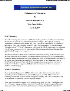
Fig. 1. Principal instantiation of a TTA processor. FU: Function unit. RF: Register file. LSU: Load-store unit. Dots represent socket connections.
3. TRANSPORT TRIGGERED ARCHITECTURES Transport triggered architectures (TTA) reduce the bypass complexity of VLIW architectures by making the bypass registers visible at the architectural level. This allows to reduce the number of read and write connections and the number of bypass buses. In the TTA programming model, the program specifies only the data transports (moves) to be performed by the interconnection network [2]. Operations occur as “side-effect”. The data transports are scheduled during compile-time. The number of data transports per instruction is equal to the number of simultaneous transports allowed by the interconnection network. A TTA processor consists of a set of functional units and register files containing general-purpose registers. These structures are connected to an interconnection network consisting of buses through input and output sockets as illustrated in Fig. 1. The architecture can easily be tailored by adding or removing resources without any notable changes in the transport capacity. Moreover, special functional units with user-defined functionality can be easily included. MOVE framework is a toolset for designing applicationspecific instruction set processors that utilize the transport triggering concept [10]. It provides a semi-automatic design process that can shorten significantly the design-time. The MOVE framework exploits the scalability, flexibility, and simplicity of TTAs. The design flow consists of three main components. The design space explorer searches for processor configurations that yield the best cost/performance ratio for a given application. The hardware subsystem is responsible for generating the target processor. The software subsystem generates instruction-level parallel code for the chosen processor configuration. TTA processors designed with the MOVE framework are called MOVE processors. One of the biggest drawbacks of TTA is its poor code density that is mostly due to long instruction words that contain dedicated fields, called move slots, for each bus to define data transports on the buses. Each move slot contains three fields, as illustrated in Fig. 2. Guard field specifies the guard value that controls if the data transport on the bus is executed or not. Destination ID field specifies the address
of the socket that reads data from the bus and the source ID field the address of the socket that writes data on the bus. In addition to move slots, instruction words may contain dedicated fields to define long immediate values. Long immediate fields are mainly used to specify jump addresses and immediate values that require more than eight bits. The TTA programming model is another reason for poor code density. Splitting a single operation into multiple data transports means specifying the FU multiple times. Furthermore, because the compiler may be unable to fully exploit the parallelism available in the application to schedule data transports on all buses, the number of empty data transports gets large. For example, in the case of branch instructions the compiler might not be able to schedule data transports to delay slots resulting in instructions that specify only empty data transports. 4. INSTRUCTION TEMPLATES In VLIW architectures, the compiler might not be capable of fully exploiting the parallelism of the application to schedule operations for each concurrently operating functional unit. This results in NOPs and waste of instruction bits. A method using multiple instruction formats, or instruction templates, to avoid explicit specification on NOPs for VLIW and EPIC architecture has been proposed in [4]. Instruction templates provide operation slots for just a subset of the functional units. The rest of the functional units receive NOPs implicitly. This compression scheme results in variable-width instructions and, consequently, in more complex instruction fetch and decode logic. Instruction fetch packet and instruction register need to be at least as long as the longest instruction. When the instruction is shorter, the remaining portion of the fetched packet, which belongs to the next instruction, needs to be shifted at the beginning of the instruction register before beginning fetching the next instruction. The remaining portion is then concatenated with the fetched instruction. Each compressed instruction contains a fixed-
grd
dst ID move slot 0
src ID
grd
dst ID
src ID
reserved immediate field
move slot 1
Fig. 2. Principal organization of a MOVE instruction. width template selection field at the beginning of the instruction to identify the template that has been used to code the original instruction. From its value the instruction decoder obtains the number of operation slots, their widths and their bit positions. The cost of the instruction fetch and decode logic becomes significant when the number of templates gets large. Due to this, it is not cost-effective to have instruction templates for every possible operation slot combination that appears in a program [11]. If there are n functional units, there are 2n possible operation slot combinations. Often, only a small fraction of them are used in the program. The original program needs to be profiled to find out, which operation slot combinations are used. A limited set of templates capable of covering all the possible combinations is chosen on the basis of the profiling information. If the instruction template for a given instruction is not available, a template specifying a superset of the operation slots to be coded must be chosen. On the unused operation slots of the superset template NOPs are explicitly specified. 5. APPLYING INSTRUCTION TEMPLATES ON MOVE INSTRUCTIONS Instruction templates can be applied to MOVE instructions in a fashion similar to that used for VLIW instructions. Instead of specifying operation slots for a subset of functional units, the instruction templates specify move slots for a subset of buses; the rest of the buses obtain null transports implicitly. In addition to move slots, dedicated immediate fields are also considered as elements of the instruction templates. Thus, if a long immediate value is not needed, it is not specified in the instruction template. The structure of the compressed instruction word of a MOVE processor is depicted in Fig. 3. The template selection field at the beginning of the instruction specifies the used template. In high performance MOVE processors, the large number of buses results in large number of move slot and dedicated immediate field combinations. The number of templates needs to be limited to avoid too expensive decompression hardware. A scheduled program needs to be profiled to find the frequencies of all move slot and dedicated long immediate field combinations, i.e., to count how many times each combination appears in the program code. The most beneficial combinations are chosen as templates. The benefit of each combination included in the template set is cal-
move slot 0
move slot 3
.....
move slot n
reserverd immediate field n
template selection field
Fig. 3. Principal organization of an instruction template for MOVE processors. culated, and on each iteration of the selection algorithm the most profitable combination is chosen as a template. The selection algorithm is described in more detail in [4]. 6. BENCHMARKS To evaluate the code density improvements achievable by the instruction template method, six different benchmarks are used. The first four are applications from DSP application domain. Two first benchmark tasks realize Discrete cosine transform (DCT), a kernel widely used in video, image, and audio coding. Here the constant geometry twodimensional (2-D) DCT algorithm proposed in [12] and 1-D DCT proposed in [13] have been considered. Constant geometry algorithms are regular and modular. Thus, they allow efficient exploitation of parallelism. The 2-D 8x8 DCT was realized with row-column approach, i.e., the entire 2D transform is realized with the aid of 1-D transforms. The 1-D 32-point DCT contains five functions, each corresponding to one processing stage of the transform. Each processing stage is written totally unrolled, i.e., without loops. In general, this type of code results in large program size. The third benchmark is Viterbi decoding [14], an algorithm widely used in many decoding and estimation applications in the communications and signal processing domain. The algorithm decodes 256-state 1/2-rate convolutional codes and, contains path metric computation and survivor path search. The fourth benchmark performs edge detection with 3x3 Sobel masks. Masks are applied separately for horizontal and vertical direction and edges are obtained after thresholding. The last two benchmarks are mpeg2 decoding and jpeg compression, which have been taken from the MediaBench benchmark set [15]. The mpeg2 decoding application has been written in a way to emphasize the correct implementation of the moving picture expect group (MPEG) standard. The jpeg compression application performs jpeg compression from a variety of graphic file formats using the joint picture expert group (JPEG) standard. These six benchmarks represent applications from DSP and multimedia domains. All of them are written in C using integer data types. This way, no floating-point arithmetics is required. Furthermore, the DCT applications are realized using fixed-point representation with normalized number ranges, which is typical for DSP realizations. The DCT applications, Viterbi decoding, and edge detection al-
gorithms have been optimized for DSP. The mpeg2 decoding and jpeg compression applications have been written as precise specifications of the MPEG and JPEG standards and, are not optimized for DSP. The applications also vary widely in program size. Applications optimized for DSPs are small whereas mpeg2 decoding and jpeg compression are fairly large applications. 7. EXPERIMENTAL RESULTS The design space explorer of the MOVE framework was first used to perform processor resource optimization for each benchmark [10]. From the results of the resource optimization, three processor configurations were chosen for each benchmark. These configurations varied in the number of resources. A configuration having a large number of buses was chosen to represent a configuration that has a high performance but also a high cost. The second configuration was a cost-efficient configuration with only few number of buses. The third configuration was selected halfway between the two other configurations. After choosing the processor configurations, connectivity optimization was performed on each configuration to reduce unnecessary connections from the transport network. After the optimized processor configurations were obtained, each benchmark was compiled for the three processor configurations optimized for it. Template selection was then performed using the profiling information. Example. The following example illustrates the template selection applied to the smallest processor configuration of 8x8 2-D DCT. During the profiling phase, 12 different move slot and dedicated long immediate field combinations, shown in Fig. 5a, were found. The instruction word is 86 bits wide. The profit of each combination was then evaluated, and four most beneficial combinations were chosen as templates according to the algorithm presented in [4]. The chosen templates with corresponding instruction formats are shown in Fig. 5b. These four templates results already in 31 percent reduction in code size. The instruction widths, the number of instructions, and program code sizes for each benchmark on each processor configuration are listed in Table 1. The size of the program varies considerably depending on the application and the target processor configuration. The big difference is mainly caused by the number of instructions. Fig. 4 depicts the relative code sizes for each benchmark on different processor configurations, which are classified according to the number of buses. All other resources are scaled correspondingly, except that all configurations contained only one dedicated long immediate field. The number of templates is varied between 2 and 32. In addition, the case of having a template for all profiled move slot and dedicated long immediate combinations is evaluated. Fur-
Combinations
Frequency
move1 move2 move3
-
move1 move2 move3 limm -
-
75 42
-
-
15
move1 move2
-
-
15
move1
-
-
-
14
move1
-
move3
-
13
move1 move2
-
-
-
move3
move1
-
-
-
limm limm
move2 move3
move1
-
-
move2
-
move3 limm -
-
12 7 6 5 3 1
a) Chosen templates
Width ( bits)
00 move1 move2 move3 limm
88
01 move1 move2 move3
56
10 move1
20
11 move1 move3
38
b)
Fig. 5. a) Profiled move slot and dedicated long immediate field combinations with their frequencies for the smallest configuration of the 8x8 2-D DCT application. b) Organization of the four chosen templates and their widths.
thermore, the lower bound code sizes (effective code size) for each configuration are illustrated. This is a theoretical upper bound of code size reduction and does not include bits needed to specify empty data transports nor variablewidth encoding support information. The relative code sizes shown in Fig. 4 are relative to the uncompressed code size of the largest program of each benchmark. A significant reduction in code size can already be seen with four instruction templates. As more templates are introduced, the code size decreases, approaching the lower bound. This, however, cannot be reached, because the template selection field at the beginning of each instruction requires additional bits. With the maximum number of templates the code size can be reduced to about 30 percent of the largest uncompressed program size in all benchmarks except for the 32-point DCT. The program size of this application can be reduced to only about 70 percent of the largest program size. On smallest processor configurations no notable decrease in code size is noted after eight templates due to small number of move slot and dedicated long
uncompressed code
2 templates
4 templates
8 templates
16 templates
32 templates
n max templates
effective code
1.0
1.0
1.0
0.8
0.8
0.8
0.6
0.6
0.6
0.4
0.4
0.4
0.2
0.2
0.2
0.0
13 buses
8 buses
3 buses
0.0
10 buses
8x8 2D DCT
8 buses
3 buses
0.0
32-point DCT 1.0
1.0
0.8
0.8
0.8
0.6
0.6
0.6
0.4
0.4
0.4
0.2
0.2
0.2
9 buses
5 buses
3 buses
0.0
edge detection
8 buses
6 buses
MPEG2 decoding
6 buses
3 buses
Viterbi
1.0
0.0
9 buses
5 buses
0.0
13 buses
7 buses
3 buse
JPEG compression
Fig. 4. Relative code sizes of benchmarks on different processor configurations with different number of templates. In addition, the lower bound of code size (effective code size), where all NOPs have been removed without overhead, is shown. immediate field combinations in the program. The different results for the 32-point DCT application are caused by the fact that the iterations in the application were completely unrolled. Because of this, the scheduler was capable of utilizing buses more efficiently, resulting in less empty data transports and less opportunities for code size reduction. This can also be seen from the large effective code sizes of the 32-point DCT benchmark compared to other benchmarks. From Fig. 4 it can be noted that the effective code sizes of different processor configurations are almost the same. This suggests that, if all empty data transports can be removed without overhead, the resulting code size may not depend on the processor configuration. As illustrated in Fig. 4, when more templates are used, the compressed code sizes of different processor configurations start to approach each other. This means that the same functionality with better performance but almost the same code size can be achieved when instruction templates are applied. This eases the selection of the most suitable processor configuration for the application. Typically, a configuration being a compromise between performance and cost has to be chosen.
High-performance configurations have larger hardware area and increased code size. When instruction templates are applied, the relative impact of code size on the overall cost of the processor is reduced, since the compressed program size is almost independent of the chosen processor configuration. Thus, by applying instruction templates a configuration with high performance can be chosen without having to pay the full cost of increased program code.
8. CONCLUSIONS In this paper, instruction templates were applied to TTA instructions of six benchmark applications to improve the code density. It was shown that by applying instruction templates the code size can be reduced to about 30 percent of the original program size. Thus, the code wastage caused by the unused data transport slots can be reduced drastically. Furthermore, results indicate that the compressed code sizes for different processor configurations are quite close to each other. This eases the selection of a processor configuration that fulfills the performance and cost requirements.
Table 1. Statistics of benchmark applications with different processor configurations. Application
8x8 2-D DCT 8x8 2-D DCT 8x8 2-D DCT 32-point DCT 32-point DCT 32-point DCT Viterbi Viterbi Viterbi edge edge edge mpeg2dec mpeg2dec mpeg2dec cjpeg cjpeg cjpeg
Buses
13 8 3 10 8 4 9 6 3 9 5 3 8 6 5 13 7 3
Instr. width [bits] 261 179 86 196 160 96 200 146 89 207 126 89 184 145 127 272 160 91
Instr. count
Code size [bytes]
127 138 208 477 502 1038 253 262 385 565 605 644 7652 8018 8550 12198 12248 12909
4144 3088 2236 11687 10040 12456 6325 4782 4283 14619 9529 7165 175996 145326 135731 414732 244960 146840
9. REFERENCES
[6] J. Hoogerbrugge, L. Augusteijn, J. Trum, and R. van de Wiel, “A code compression system based on pipelined interpreters,” Software - Practice and Experience, vol. 29, no. 11, pp. 1005–1023, 1999. [7] Y. Xie, W. Wolf, and H. Lekatsas, “A code decompression architecture for VLIW processors,” in Proc. 34th Annual Symp. on Microarchitecture, Dec. 1–5 2001, pp. 66–75. [8] S. Y. Larin and T. M. Conte, “Compiler-driven cached code compression schemes for embedded ILP processors,” in Proc. 32nd Annual Symp. on Microarchitecture, Nov. 16–18 1999, pp. 82–92. [9] J. Heikkinen, J. Takala, and J. Sertamo, “Code compression on transport triggered architectures,” in Proc. Int. Workshop on System-on-Chip for Real-Time Applications, Banff, AB, Canada, July 6–7 2002, pp. 186–195. [10] H. Corporaal and M. Arnold, “Using transport triggered architectures for embedded processor design,” Integrated Computer-Aided Engineering, vol. 5, no. 1, pp. 19–38, 1998. [11] S. Aditya, S. A. Mahlke, and B. R. Rau, “Code size minimization and retargetable assembly for custom EPIC and VLIW instruction formats,” ACM Transactions on Design Automation of Electronic Systems, vol. 5, no. 4, pp. 752–773, Oct. 2000.
[1] H. Suzuki, H. Makino, and Y. Matsuda, “Novel VLIW code compaction method for 3D geometry processors,” in Proc. IEEE Custom Integrated Circuits Conf., Orlando, FL, U.S.A., May 21–24 2000, pp. 555–558.
[12] J. Kwak and J. You, “One- and two-dimensional constant geometry fast cosine transform algorithms and architectures,” IEEE Trans. Signal Processing, vol. 47, no. 7, pp. 2023–2034, July 1999.
[2] H. Corporaal, Microprocessor Architectures: From VLIW to TTA, John Wiley & Sons, Chichester, UK, 1997.
[13] J. Takala, D. Akopian, J. Astola, and J. Saarinen, “Constant geometry algorithm for discrete cosine transform,” IEEE Trans. Signal Processing, vol. 48, no. 6, pp. 1840–1843, June 2000.
[3] A. Wolfe and C. Chanin, “Executing compressed programs on an embedded RISC processor,” in Proc. 25th Annual Symp. on Microarchitecture, Portland, OR, U.S.A., Dec. 1–4 1992, pp. 81–91.
[14] A. J. Viterbi, “Error bounds for convolutional coding and an asymptotically optimum decoding algorithm,” IEEE Trans. Inform. Theory, vol. 13, pp. 260–269, Apr. 1967.
[4] S. Aditya, B. R. Rau, and R. C. Johnson, “Automatic design of VLIW and EPIC instruction formats,” Tech. Rep. HPL-1999-94, Hewlett-Packard Laboratories, 2000.
[15] C. Lee, M. Potkonjak, and W. H. Mangione-Smith, “MediaBench: A tool for evaluating and synthesizing multimedia communications systems,” in Proc. 30th Annual Symp. on Microarchitecture., Research Triangle Park, NC, U.S.A., Dec. 1–3 1997, pp. 330– 335.
[5] S. J Nam, I. C. Park, and C. M. Kyung, “Improving dictionary-based code compression in VLIW architectures,” IEICE Trans. Fundamentals of Electronics, Communication and Computer Sciences, vol. E82-A, no. 11, pp. 2318–2124, Nov. 1999.