a vision system inspired upon the visual system of the fly. The 10 kg .... The evolved spiking circuit clearly reacts when it hits the wall by turning off the motors ...
Evolving Vision-Based Flying Robots Jean-Christophe Zufferey, Dario Floreano, Matthijs van Leeuwen, and Tancredi Merenda Autonomous Systems Laboratory (asl.epfl.ch), Institute of Systems Engineering, Swiss Federal Institute of Technology (EPFL), CH-1015, Lausanne, Switzerland
Abstract. We describe a new experimental approach whereby an indoor flying robot evolves the ability to navigate in a textured room using only visual information and neuromorphic control. The architecture of a spiking neural circuit, which is connected to the vision system and to the motors, is genetically encoded and evolved on the physical robot without human intervention. The flying robot consists of a small wireless airship equipped with a linear camera and a set of sensors used to measure its performance. Evolved spiking circuits can manage to fly the robot around the room by exploiting a combination of visual features, robot morphology, and interaction dynamics.
1
Bio-Inspired Vision for Flying Robots
Our goal is to develop vision-based navigation systems for autonomous miniature (below 80 cm, 50 g) flying robots [1]. Some research teams are working on even smaller dimensions [2,3,4], but their efforts are essentially concentrated on mechatronics issues. A major challenge for miniature flying robots is the ability to navigate autonomously in complex environments. Conventional distance sensors (laser, ultrasonic) cannot be used for these systems because of their weight. Vision is an interesting sensor modality because it can be lightweight and low-power. However, the mainstream approach to computer vision, based on segmentation, object extraction, and pattern recognition, is not always suitable for small behavioural systems that are unable to carry powerful processors and related energy sources. An alternative consists in taking inspiration from simple circuits and adaptive mechanisms used by living organisms [5]. A pioneering work in this direction was achieved by Franceschini et al. [6], who developed a wheeled robot with a vision system inspired upon the visual system of the fly. The 10 kg synchrodrive robot featured an artificial compound eye with 100 discrete photoreceptors and was able to freely navigate at about 50 cm/s toward a light source while avoiding randomly arranged obstacles. Other successful realisations followed (for review, see [7]), but unlike the robot by Franceschini et al., where computation was executed onboard by analog electronics, those machines demanded more computing power and were therefore linked to offboard computers for image processing. More recent work uses bio-inspired visual algorithms in flying agents, H.H. B¨ ulthoff et al. (Eds.): BMCV 2002, LNCS 2525, pp. 592–600, 2002. c Springer-Verlag Berlin Heidelberg 2002 �
Evolving Vision-Based Flying Robots
593
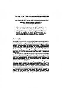
Fig. 1. Evolutionary vision-based robots. Left: The Khepera robot equipped with a linear camera (16 pixels, 36◦ FOV) was positioned in an arena with randomly sized black and white stripes. Random size was used to prevent development of trivial solutions whereby the control system would use the size of the stripes to measure distance from walls and self-motion. The robot was connected to a workstation through rotating contacts that provided serial data transmission and power supply. Right: The blimp-like flying robot, provided with a similar linear camera (16 pixels, 150◦ FOV), is closed in a 5x5x3 m room with randomly sized black and white stripes on the walls. The serial data transmission is handled by a BluetoothTM wireless connection and power supply by an onboard battery.
but these developments have been limited to tethered aircraft [8] and simulated flight [9]. The control systems of the robots mentioned above were ‘hand-designed’. Some authors proposed to evolve vision-based navigation capabilities [10,11]. For example, Huber applied genetic algorithms to simulated 2D agents [12]. Those agents were equipped with only four photoreceptors making up two elementary motion detectors (EMD), symmetrically placed on each side of the agent. The parameters of those EMDs as well as the position and field of view (FOV) of the photoreceptors were evolved. The best individuals could successfully navigate in a simulated corridor with textured walls and obstacles. The simulation was rather simple though, especially because inertial forces were not taken into consideration. In previous work [13], we evolved the architecture of spiking neural networks capable of steering a vision-based, wheeled robot. A Khepera robot with a linear camera was asked to navigate in a rectangular arena with textured walls (figure 1, left). The best individuals were capable of moving forward and avoiding walls very reliably. However, the complexity of the dynamics of this terrestrial robot is much simpler than that of flying agents. In this paper, we extend that approach to a flying robot (figure 1, right) that is expected to navigate within a room using only visual information. Genetic algorithms [14] are used to evolve the architecture of a spiking circuit, which connects low resolution visual input to the motors of a small indoor airship. Notice that other teams are using blimps for studying insect-like vision-based
594
J.-C. Zufferey et al.
navigation [15,16], but none of them are applying the concepts of evolutionary robotics [17]. In the following section, we describe the main challenges of running evolution with real flying systems and give an overview of the experimental setup. Section 3 summarizes the evolutionary and neural dynamics. The results are presented in section 4. Finally, a discussion and future work description are given in section 5.
Fig. 2. The blimp features an ellipsoid envelope (100x60x45 cm) filled with helium for a lift capacity of approximately 250 g. On top and below the envelope are attached frames made of carbon fibre rods that support six bumpers (4 on top and 2 below) for collision detection. It is equipped with three engines (miniature DC motor, gear, propeller): two for horizontal movement (forward, backward and rotation around yaw axis) and one for vertical movement. In order to measure the relative forward airspeed, an anemometer (free rotating balsa-wood propeller with a mouse optical encoder) has been mounted on top of the envelope. The system is able to qualitatively measure airspeeds above 5 cm/s. A distance sensor has been mounted below the gondola and oriented toward the floor for altitude control in the preliminary experiments.
2
Experimental Setup
Evolving aerial robots brings a new set of challenges. The major issues of developing (evolving, learning) a control system for an airship, with respect to a wheeled robot, are (1) the extension to three dimensions1 , (2) the impossibility to communicate to a computer via cables, (3) the difficulty of defining and measuring performance, and (4) the more complex dynamics. For example, while the Khepera is controlled in speed, the blimp is controlled in thrust (speed derivative) and can slip sideways. Moreover, inertial and aerodynamic forces play a major role. Artificial evolution is a promising method to automatically develop 1
Although the first experiments described hereafter are limited to 2D by the use of a pre-designed altitude regulator.
Evolving Vision-Based Flying Robots
595
Fig. 3. Left: The blimp and its main components: the anemometer on top of the envelope, the linear camera pointing forward with 150◦ FOV giving a horizontal image of the vertical stripes, the bumpers and propellers. Right: Contrast detection is performed by selecting 16 equally spaced photoreceptors and filtering them through a Laplace filter spanning three photoreceptors. Filtered values are then rectified by taking the absolute value and scaling them in the range [0,1]. These values represent the probability of emitting a spike for each corresponding neuron. A linear camera fixed on the gondola is the only source of information for the evolutionary spiking network.
control systems for complex robots [17], but it requires machines that are capable of moving for long periods of time without human intervention and withstand shocks. Those requirements led us to the development of the blimp shown in figure 2. All onboard electronic components are connected to a Microchip PICTM microcontroller with a wireless connection to a desktop computer. The bidirectional digital communication with the computer is handled by a BluetoothTM radio module, allowing more than 15 m range. The energy is provided by a Lithium-Ion battery, which lasts more than 3 hours under normal operation, during evolutionary runs. For purpose of analysis, the evolutionary algorithm and spiking circuits are implemented on the desktop computer which exchanges sensory data and motor commands with the blimp every 100 ms.2 In these experiments, a simple linear camera is attached in front of the gondola (figure 3), pointing forward. The fish-eye-view lens gives a horizontal 150◦ FOV mapped onto 16 photoreceptors (subsampled from about 50 active pixels) whose activations are convolved with a Laplace filter. The Laplace filter detects contrast over three adjacent photoreceptors.
2
An adapted form of the evolutionary algorithm and spiking circuit could be run on the onboard microcontroller [18], but data analysis would be limited.
596
J.-C. Zufferey et al. sign
synapse presence
.. .
Sensory receptor
..
.
Neurons
Motor output
Sensory receptors
.. .
.. .
Neurons (t-1)
.. . synaptic connections
Fig. 4. Network architecture (only a few neurons and connections are shown) and genetic representation of one neuron. Left: A conventional representation showing the network architecture. Four neurons, two for each side, are used to set the speeds of the two horizontal propellers in a push-pull mode. Right: The same network unfolded in time (neurons as circles, synaptic connections as squares). The neurons on the column receive signals from connected neurons and photoreceptors shown on the top row. The first part of the row includes the same neurons at the previous time step to show the connections among neurons. Sensory neurons do not have interconnections. The signs of the neurons (white = excitatory, black = inhibitory) and their connectivity pattern is encoded in the genetic string and evolved.
3
Evolving Spiking Circuits
The evolutionary method and the spiking controller are very similar to what is described in [13]. The connectivity pattern and neuron signs of a network of 10 spiking neurons connected to 16 spiking visual receptors is genetically encoded and evolved using a standard genetic algorithm [14] with a population of 60 individuals sequentially evaluated on the same physical robot. The architecture is genetically represented by a binary string composed of a series of blocks, each block corresponding to a neuron. The first bit of a block encodes the sign of the corresponding neuron (1, -1) and the remaining 26 bits encode the presence/absence (1, 0) of a connection from the 10 neurons and from the 16 visual receptors (figure 4). The synaptic strengths of all existing connections are set to 1. The spiking neuron model includes the response profile of synaptic and neuron membranes to incoming spikes, time delays to account for axon length, and membrane recovery profile of the refractory period [19]. The parameter values for the equations are predefined and fixed for all networks (no tuning has been done on these parameter values). The population of 60 individuals is evolved using rank-based truncated selection, one-point crossover, bit mutation, and elitism [17]. The genetic strings of the first generation are initialised randomly. After ranking the individuals according to their measured fitness values, the top 15 individuals produce 4 copies each to create a new population of the same size and are randomly paired for
Evolving Vision-Based Flying Robots
597
crossover. One-point crossover is applied to each pair with probability 0.1 and each individual is then mutated by switching the value of a bit with probability 0.05 per bit. Finally, a randomly selected individual is substituted by the original copy of the best individual of the previous generation (elitism). Each individual of the population is tested on the robot two times for 40 seconds each (400 sensory-motor steps). The behaviour of an individual is evaluated by mean of the anemometer, which rotation speed is approximately proportional to the forward motion. The fitness function is thus the amount of estimated forward motion vˆ at every time step t (100 ms) averaged over all T time steps available (T =800):
Φ=
T 1� t vˆ T t
(1)
After each 40 s test, a preprogrammed random movement of 5 seconds is executed to create a randomised initial situation for the next test.
4
Results
We performed five evolutionary runs, each starting with a different random initialisation (figure 5, top left). All best evolved individuals of the five runs developed efficient strategies in less than 20 generations (2-3 days) to navigate around the room in the forward direction. Interestingly, walls are actively used by the robot to stabilise the trajectory. The fitness function (section 3) does not ask individuals to avoid walls, but only to maximise forward motion. The anemometer rotates only if the forward component of the speed vector is not null. The trajectory of a typical best individual is shown on the top right plot of figure 5. It starts with a rotational movement due to the previous random movement (a) and keeps rotating until it hits a wall, which stabilises its course (b). It then moves straight forward until a wall is hit frontally (c), the motors are turned off, and the robot bumps backward. When the robot is free from the wall, the motors are turned on to move forward. Once again, a wall is used to stabilise the course and the same strategy is repeated over and over again. The evolved spiking circuit clearly reacts when it hits the wall by turning off the motors, although the only input to the neural network is vision data. This behaviour can be seen also in the pattern of motor activity shown in the bottom graphs of figure 5, which indicates a strong correlation between a collision event3 and change of motor speeds. It is quite remarkable that such a simple evolved spiking circuit is able to detect collisions with so poor visual information about the environment, using only 16 photoreceptors as input. 3
Note that with the current setup, it is not possible to know which of the six bumpers is in contact with the walls. As a consequence, we cannot distinguish between a frontal and a side collision.
J.-C. Zufferey et al.
0.5
598
b c
0.4
a
Fitness
0.3
+ + + +
+ +
+ +
+
+ +
+
+ 0.2
+ +
+ + + +
0.1
+
0.0
+
0
5
10
15
20
1.0
0.0 1.0 0.0 0.0 1.0 0.0
1.0 0.0
Motor right
Motor left
Motors
Speed
1.0
Collisions
Generation
0
20
40
60
80
100
120
Time (s)
Fig. 5. Top left: Average fitness values of five evolutionary runs (best fitness = crosses, average fitness = circles). Each data point is the average of five evolutionary runs starting with different random initialisation of the chromosomes. Top right: Handdrawn estimation of the typical path of the selected best individual (solid line = forward movement; dashed line = backward movement; small curves = front collision; cross and circle = place of collision with left back bumper). Bottom: Performance of the best selected individual during two minutes. The upper graph shows collisions, as detected by the bumpers. The second graph shows an approximation of the forward speed, as measured with the anemometer. The motor graphs show the forward thrust of the propellers, which is given by the neural network output (‘Motors’ is the average of both motors). Each vertical line indicates the start of a collision. Multiple collisions on the topgraph are generated by the switches of the bumpers as the robot touches the walls.
Evolving Vision-Based Flying Robots
5
599
Conclusion
These initial explorations with simple neuromorphic vision controllers for flying robots indicate that artificial evolution can discover efficient (and unexpected) solutions that capitalize on a combination of visual information and interaction dynamics between the physical system and its environment. These evolved solutions can not only encompass visual mechanisms already discovered in insects (such as forms of elementary motion detection), but also incorporate new “tricks” that may, or may not, be used by biological flying organisms. In current work, we are investigating the behavioural effects of different types of imaging devices (such as aVLSI retina) and preprocessing filters (temporal, spatial, spatio-temporal, EMDs, etc.). A 3D flight simulator under development will help us to speed up evolutionary runs, let the sensor morphology evolve along with the controller, but will require proper handling of the issues related to the differences between simulation and real world. This last point will probably be approached by evolving hebbian-like synaptic plasticity, which we have shown to support fast self-adaptation to changing environments [20]. Eventually, our goal is to apply this approach to indoor slow flyers with wings [1], instead of airships. Acknowledgements. This work was supported by the Swiss NSF grant No. 620-58049. The authors are grateful to Jean-Daniel Nicoud (www.didel.com) for providing parts and support for building the blimp, and to Cyril Halter for the wind tunnel tests. Portescap (www.portescap.com) provided the motors equipping the blimp and Sensile (www.sensile.ch) the force gauges for the wind tunnel setup.
References 1. Nicoud, J.D., Zufferey, J.C.: Toward Indoor Flying Robots. To appear in proceedings of IEEE/RSJ International Conference on Intelligent Robots and Systems (2002) 2. Fearing, R.S., Chiang, K.H., Dickinson, M.H., Pick, D.L., Sitti, M., and Yan, J.: Wing Transmission for a Micromechanical Flying Insect. IEEE Int. Conf. Robotics and Automation (2000) 3. Pornsin-Sirirak, T.R., Lee, S.W., Nassef, H., Grasmeyer J., Tai, Y.C., Ho, C.M., Keennon, M.: MEMS Wing Technology for A Battery-Powered Ornithopter. The 13th IEEE International Conference on Micro Electro Mechanical Systems (MEMS’00), Miyazaki, Japan, pp. 799–804 (2000) 4. Kroo, I. et al.: The Mesicopter: A Meso-Scale Flight Vehicle. http://aero.stanford.edu/mesicopter/ 5. Pfeifer, R., Lambrinos, D.: Cheap Vision – Exploiting Ecological Niche and Morphology. Theory and practice of informatics: SOFSEM 2000, 27th Conference on Current Trends in Theory and Practice of Informatics, pp. 202–226 (2000) 6. Franceschini, N., Pichon, J.M., Blanes, C.: From insect vision to robot vision. Phil. Trans. R. Soc. Lond. B, 337, pp. 283–294 (1992)
600
J.-C. Zufferey et al.
7. Weber, K., Venkatesh, S., Srinivasan, M.V.: Insect Inspired Behaviours for the Autonomous Control of Mobile Robots. From Living Eyes to Seeing Machines, pp. 226–248 (1997) 8. Netter, T., Franceschini, N.: A Robotic Aircraft that Follows Terrain Using a Neuromorphic Eye. To appear in Proceedings of IEEE/RSJ International Conference on Intelligent Robots and Systems (2002) 9. Neumann, T.R., B¨ ulthoff, H.H.: Insect Inspired Visual Control of Translatory Flight. ECAL (2001) 10. Harvey, I., Husbands, P., Cliff, D.: Seeing the Light: Artificial Evolution, Real Vision. In From Animals to Animats III, MIT Press, pp. 392–401 (1994) 11. Dale, K., Collett, T.S. Using artificial evolution and selection to model insect navigation. Current Biology, 11:1305-1316 (2001) 12. Huber, S.A., Mallot, H.A., B¨ ulthoff, H.H: Evolution of the sensorimotor control in an autonomous agent. In Proceedings of the Fourth International Conference on Simulation of Adaptive behaviour, MIT Press, pp. 449–457 (1996) 13. Floreano, D., Mattiussi, C.: Evolution of Spiking Neural Controllers for Autonomous Vision-Based Robots. In Gomi, T., ed., Evolutionary Robotics. From Intelligent Robotics to Artificial Life. Tokyo: Springer Verlag (2001) 14. Goldberg, D.E.: Genetic Algorithms in Search, Optimization and Machine Learning. Reading, MA: Addison-Wesley (1989) 15. Iida, F.: Goal-Directed Navigation of an Autonomous Flying Robot Using Biologically Inspired Cheap Vision. In Proceedings of the 32nd International Symposium on Robotics (2001) 16. Planta, C., Conradt, J., Jencik, A., Verschure, P.: A Neural Model of the Fly Visual System Applied to Navigational Tasks. In Proceedings of the International Conference on Artificial Neural Networks, ICANN (2002) 17. Nolfi, S., Floreano, D.: Evolutionary Robotics: Biology, Intelligence, and Technology of Self-Organizing Machines. Cambridge, MA: MIT Press. 2nd print (2001) 18. Floreano, D., Schoeni, N., Caprari, G., Blynel, J.: Evolutionary Bits’n’Spikes. Technical report (2002) 19. Gerstner, W.: Associative memory in a network of biological neurons. In Lippmann, R.P.; Moody, J.E.; and Touretzky, D.S., eds., Advances in Neural Information processing Systems 3. San Mateo,CA: Morgan Kaufmann. 84-90 (1991) 20. Urzelai, J., Floreano, D.: Evolutionary Robotics: Coping with Environmental Change. In Proceedings of the Genetic and Evolutionary Computation Conference (2000)